Forum sponsored by:

Clock Stand with a difference
| Graham Meek | 02/10/2021 12:21:44 |
| 714 forum posts 414 photos | By way of an introduction and something to get the little grey cells working. I am currently working on what for me is a Clock Stand, with a difference. The primary design was for a stable clock stand. I have for years used a Starrett Machinists Scribing Block. Using very sensitive clocks do test the various elements of this "Maid of all work", and sometimes ones patience. Whilst at the design stage it was envisaged that with a bit of care in the workmanship/manufacture the design would lend itself to being used to check a vertical surface as well. Something which has to date only been catered for by the engineers square or a cylinder square. (The engineers square can get dropped or abused) . As an additional bonus, just as I was closing up the computer for the night it dawned on me if I added a DRO scale it would also double up as a digital height gauge. I must thank Ketan for his help with this feature. Over the coming weeks I will reveal more detail as I make the parts. Currently what is shown above is what has been made this week. Photographs would I know be good but these dull and dismal days do nothing for my workshop photography. Now to exercise the little grey cells. I have worked out a way of checking that the 22 mm diameter column is truly vertical to the base. It involves making another dedicated piece of equipment to do this, something I am trying to avoid. The question is is there an easier way. I really want to quantify the accuracy of the column. Relying on the use of an engineers square or cylinder square is dependant on my poor eyesight. Your suggestions are most welcome. Regards Gray,
|
| Phil P | 02/10/2021 12:28:36 |
| 851 forum posts 206 photos | Hold the assembly in the lathe using the round column, and check the underside of the base with a DTI as you rotate it. Phil |
| duncan webster | 02/10/2021 13:04:43 |
| 5307 forum posts 83 photos | To use Phil's method you'd have to move the cross slide in/out, so unless the cross slide is truly square to the axis it won't work. Many lathes are set to machine a very slight concave on facing. You could clamp a parallel to the base so you don't have this issue, but then you're reliant on the parallel. Of course you could do it twice, second time with parallel reversed, but it's getting to be a lot of work.
|
| Michael Gilligan | 02/10/2021 13:37:41 |
 23121 forum posts 1360 photos |
MichaelG. |
| Martin Kyte | 02/10/2021 13:44:25 |
 3445 forum posts 62 photos | Could you mount a laser pointer cross wise on a boss bored 22mm and locate it on a collar on the upright to fix it's hight but allow it to rotate. Mark the spot on a distant wall. Rotate the base 180 dgrees on the surface plate and realign the pointer. If the column is not at 90 degrees to the base the spot will be at a different hight on the wall as the pointer will have moved through twice the angle at which the column is in error. That does one plane. Orienting the base through 90 degrees and repeating the above will give you the other plane. regards Martin Edited By Martin Kyte on 02/10/2021 13:45:19 |
| blowlamp | 02/10/2021 14:40:20 |
 1885 forum posts 111 photos | The cylindrical square should be your friend here. Mount the square and the column/base close to one another on a good surface plate, in such a way that they can't easily move about - maybe add some weights. Then measure the distance between them at top & bottom, with gauge blocks or similar to determine how out of square things are. Then you can make your fine adjustments from there.
Martin. |
| Peter Cook 6 | 02/10/2021 14:42:20 |
| 462 forum posts 113 photos | Martin K, doesn't that method rely on the surface plate being not only flat ( it should be) but also dead level. Edited By Peter Cook 6 on 02/10/2021 14:43:37 |
| Tony Pratt 1 | 02/10/2021 14:48:59 |
| 2319 forum posts 13 photos | I'm with Martin 'blowlamp' here, a cylinder square & decent surface plate are going to be good repeatable reference surfaces. Tony |
| Brian H | 02/10/2021 15:15:15 |
 2312 forum posts 112 photos | Quote; MichaelG. End Quote Me too Brian |
| Bazyle | 02/10/2021 16:01:50 |
 6956 forum posts 229 photos | Picking up on Martin's suggestion. Polish column to be reflective. Fix laser on wall and observe reflection, almost straight back depending on whether the table is level but that is not vital. Rotate the column and if not true the reflection will go through a max and min showing you the direction of lean. Horological version |
| DiogenesII | 02/10/2021 16:10:40 |
| 859 forum posts 268 photos | A Vee block with a perpendicular arm or extension at one end to hold a clock parallel with the column, and an accurately fitting collar around the column, would let you 'tram' the assembly against a reference surface in a similar manner to a mill head, and with a visible means of quantification / comparison.. |
| Martin Kyte | 02/10/2021 16:51:38 |
3445 forum posts 62 photos | Posted by Peter Cook 6 on 02/10/2021 14:42:20:
Martin K, doesn't that method rely on the surface plate being not only flat ( it should be) but also dead level. Edited By Peter Cook 6 on 02/10/2021 14:43:37 No it doesn't. Essentailly any point on a cylinder rotating about a fixed axis will describe a circle. Rotating the laser pointer round the column will generate a circle at any given radius. Using the same bit of wall and keeping the base of the colum in the same spot fixes the radius. If the column is spot on rotating the pointer around the column at a fixed hight will generate a circle at any fixed radius parallel to the surface plate. So rotating the whole unit through 180 and keeping the pointer oriented at the spot on the wall will test this. If the column is at an angle the circle will be angled by the same amount relative to the surface plate. Swing the unit through 180 degrees and the circle will be tipped by the same angle but the opposite way. So the spot on the wall will move up or down unless it is a right angles to the base. It doesn't even matter if the laser pointer is not square to the column either. It would be nice to use reflections but I believe the column is circular so that will not work. regards Martin If you really want to get accurate replace the laser pointer with a Theodolite telescope and train the cross hairs on a point a few hundred metres away. This is how to level a theodolite if I remember right. Aim at a distant point. with the telescope level (zero elevation on the scale). Rotate the instrument through 180 and flip the scope over so it's looking back at the point but with zero elevation in the other half circle. If the scope is still on the point then the base is level in that plane.
Edited By Martin Kyte on 02/10/2021 17:00:01 |
| Graham Meek | 02/10/2021 20:09:09 |
| 714 forum posts 414 photos | I am glad to see I have stimulated some grey cell activity. As regards Phil's answer the underside of the base is relieved such that only the outer edge of the base is in contact with the surface plate, so it would mean moving the cross-slide or clamping a parallel to the base to avoid moving the cross-slide. While I like the simplicity of Martin K's idea and it has some merit, it will not directly give me a measured error. I could use a feeler gauge beneath the base to give an idea how much the dot on the wall moves for a given feeler. A sort of calibrated scale. I do wonder if any error in the construction of the laser holder and the required squareness of the face of the collar to retain a height setting would influence the results during the turn around. This being my only reservation with this idea. Regards Gray, |
| Kiwi Bloke | 03/10/2021 09:22:17 |
| 912 forum posts 3 photos | I'm hesitant to suggest a solution, because I think it's well-known, so I suspect I may have misunderstood the problem. Arrange some form of stand which can carry a dial indicator to bear radially near the top of the column to be tested, both stand and test-piece sitting on a surface plate. The indicator-carrying stand needs to have a second, fixed, elephant-foot-like 'probe', bearing on the column to be tested, as low as possible. The purpose of this second 'probe' is simply to allow the stand carrying the 'probe', etc. to clear the base of the column and to act as an horizontal datum. The fixed 'probe' lies vertically below the indicator's probe. With the fixed 'probe' bearing on the lower part of the column, the indicator will read out-of-truth as the column is rotated. As you'll realise, a V-shaped end to the fixed 'probe' makes life easier... |
| Graham Meek | 03/10/2021 15:23:18 |
| 714 forum posts 414 photos | Kiwi Bloke, I like your idea as it can be trailed easily using my FB2 milling machine, tomorrow. Regards Gray,
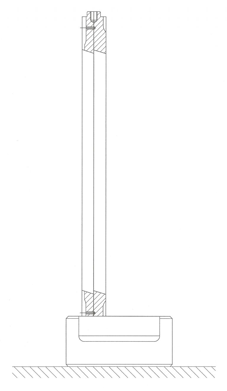
My original idea was to make the Checking Tool below, but thanks to several trains of thought put forward, I can now check this before I set too making the tool.
The Ball at the top of the column gives a constant point of contact. Two 1/4" ball bearings in each of the arms contact the column 90 degrees apart. The weight of the DTI will probably tend to pull the top arm out of contact, so the clamping screw may be needed. An additional screw might also be needed in the lower arm due to the reaction from the force the clock exerts on the probe. The Tool is first clamped to the one side of the column and the DTI is set to zero. Releasing the clamping screw(s) the tool is raised and rotated about the column and reset. Any deviation will be shown on the clock. Regards Gray, |
| Howard Lewis | 03/10/2021 17:13:15 |
| 7227 forum posts 21 photos | Might be a daft idea, but. Take an angle plate and check that the faces are truly square to each other. Clamp to the Surface plate. Clamp the Base to the Angle Plate Set a clock to Zero on the bottom of the column. Move clock to top of column. Disregarding any sag, if the readings are both Zero, the column is square to the base. Rotate base by 90 degrees, and repeat for the other plane The clock should tell you how far the column is out of square to the base, so that the base can be, presumably, scraped to eliminate the errors. Howard |
| Graham Meek | 03/10/2021 17:40:12 |
| 714 forum posts 414 photos | Hi Howard, The problem lies in determining how square the angle plate is, to start off with. I am not saying your method would not work, but. I have two angle plates made by EMCO which checked with my Cylinder Square show no deviation, (eyesight). Yet when I took them to work many years ago and checked them out using a dedicated tool for checking vertical surfaces they were out by 0.013 mm over the height of the height of the angle plate. They might well have moved in the interim. The flat surface of the surface plate is the fundamental datum in engineering, everything else comes off this. Thus any check that does not involve another variable is the best move as far as I can see. Once this Clock Stand is finished I will be able to check them again. Regards Gray,
|
| Graham Meek | 05/10/2021 12:23:46 |
| 714 forum posts 414 photos | Yesterday was spent checking the Column out. I first turned a "Cup" shaped bush to fit the top of the Column which removes the need to avoid the two key slots in the Column. As this was turned on the O/D and bored at one setting concentricity should be assured. The "Fit" on the Column was very close but I was still able to rotate the bush on the Column. The Vee block attached to the parallel in the vice machine is purposely angled down in order to present two knife edges to the Column. This ensures only point contact and that any out of squareness in the Column is not masked by a full on Vee block face. Once the set-up was ready the assembly was placed against the Vee block and the DTI brought into contact. Traversing the Y-Axis the null point was found which meant the DTI was on the Column centreline, (this procedure is repeated as the Column approaches perpendicular, to remove any further sources of error). At this point the Bush was also rotated on the Column to see if there were any errors in the machining, which there weren't. It always pays to check.
The contact face for the Column is a spot face done by mounting the part on the faceplate. The initial out of squareness was 0.1 mm in the Y-Axis in the above photographs and 0.05 mm in the X-Axis. Using my Pull Scraper and removing barely 0.005 mm from the surface of the spot face opposite the maximum errors had the Column, virtually perfect. The maximum error in the X-Axis was 0.005 mm leaning towards the centre of the Base Plate. In the Y-Axis the there was no discernable error. Turning the Column in the Base Plate by 180 degrees gave exactly the same results. Which is what I would expect as I already checked the Columns straightness using two Vee blocks and a Clock on the surface plate. To double check I might just make the tool shown above, but not until the Clock Stand is complete. Regards Gray, |
| MadMike | 05/10/2021 15:31:15 |
| 265 forum posts 4 photos | Lots of great solutions here but why not simply buy and use a height gauge to hold the clock/DTI? Or did I just scan the topic too quickly and miss something fundamental. If all you really want to do is make the stand that you described as a test of your own competence etc then I can understand the initial questions, however if you want to simply get on with with other machining then buy a ready made height gauge with a DRO fitted. |
| Graham Meek | 05/10/2021 18:11:33 |
| 714 forum posts 414 photos | Posted by MadMike on 05/10/2021 15:31:15:
Lots of great solutions here but why not simply buy and use a height gauge to hold the clock/DTI? Or did I just scan the topic too quickly and miss something fundamental. If all you really want to do is make the stand that you described as a test of your own competence etc then I can understand the initial questions, however if you want to simply get on with with other machining then buy a ready made height gauge with a DRO fitted. The opening line is that this is a Clock stand with a difference. The difference being is that this Clock Stand will traverse a DTI vertically and check to see if a machine element, or a machined face on a component is dead square to a reference surface. Such machines are an "arm and a leg" to buy, and are a dedicated item, not dual purpose. This design was initially a good Clock Stand, the facility to check a Vertical was an optional extra I thought would be good to have in the home workshop. Also I did say the DRO, to make it into a height gauge was another afterthought.
I have a Height gauge that I designed, and it has served me well for over 40 years, so really I don't really need a Digital version, but I am always open to try something new. Lastly, while a commercial Height Gauge is going to be pretty close to a true Vertical, those I have looked at give no accuracy guarantee for perpendicularity, and in 40+ years in industry I have never seen one used for this purpose. The one designed here will. Regards Gray, |


Please login to post a reply.
Magazine Locator
Want the latest issue of Model Engineer or Model Engineers' Workshop? Use our magazine locator links to find your nearest stockist!
Sign up to our Newsletter
Sign up to our newsletter and get a free digital issue.
You can unsubscribe at anytime. View our privacy policy at www.mortons.co.uk/privacy
Latest Forum Posts
- *Oct 2023: FORUM MIGRATION TIMELINE*
05/10/2023 07:57:11 - Making ER11 collet chuck
05/10/2023 07:56:24 - What did you do today? 2023
05/10/2023 07:25:01 - Orrery
05/10/2023 06:00:41 - Wera hand-tools
05/10/2023 05:47:07 - New member
05/10/2023 04:40:11 - Problems with external pot on at1 vfd
05/10/2023 00:06:32 - Drain plug
04/10/2023 23:36:17 - digi phase converter for 10 machines.....
04/10/2023 23:13:48 - Winter Storage Of Locomotives
04/10/2023 21:02:11 - More Latest Posts...
- View All Topics
Support Our Partners


Shopping Partners
Subscription Offer

Latest "For Sale" Ads
- Reeves** - Rebuilt Royal Scot by Martin Evans
by John Broughton
£300.00 - BRITANNIA 5" GAUGE James Perrier
by Jon Seabright 1
£2,500.00 - Drill Grinder - for restoration
by Nigel Graham 2
£0.00 - WARCO WM18 MILLING MACHINE
by Alex Chudley
£1,200.00 - MYFORD SUPER 7 LATHE
by Alex Chudley
£2,000.00 - More "For Sale" Ads...
Latest "Wanted" Ads
- D1-3 backplate
by Michael Horley
Price Not Specified - fixed steady for a Colchester bantam mark1 800
by George Jervis
Price Not Specified - lbsc pansy
by JACK SIDEBOTHAM
Price Not Specified - Pratt Burnerd multifit chuck key.
by Tim Riome
Price Not Specified - BANDSAW BLADE WELDER
by HUGH
Price Not Specified - More "Wanted" Ads...
Get In Touch!
Do you want to contact the Model Engineer and Model Engineers' Workshop team?
You can contact us by phone, mail or email about the magazines including becoming a contributor, submitting reader's letters or making queries about articles. You can also get in touch about this website, advertising or other general issues.
Click THIS LINK for full contact details.
For subscription issues please see THIS LINK.
Digital Back Issues


Donate

 Register
 Log-in
Model Engineer Magazine
- Percival Marshall
- M.E. History
- LittleLEC
- M.E. Clock

ME Workshop
- An Adcock
- & Shipley
- Horizontal
- Mill

Subscribe Now
- Great savings
- Delivered to your door

Pre-order your copy!
- Delivered to your doorstep!
- Free UK delivery!
All Forum Topics > Manual machine tools > Clock Stand with a difference