Forum sponsored by:

Unimat SL modifications
New member
| Clock polisher | 01/10/2021 19:24:26 |
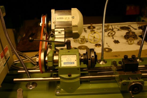
| 36 forum posts 38 photos | Good evening, I am a retired combustion engineer from the steel industry and have developed an interest in the repair of grandfather clock movements. I very quickly noted that I needed some form of lathe for this and went for the EMCO Unimat SL due to it's compact size. I tried the original motor but it was too noisy and time restrained. Then I went for a standard 90w sewing machine motor controlled via a foot pedal but as well as not being able to control my left foot the motor was not powerful enough to achieve higher speeds under load. After research I bought a 550w DC servo motor from Amazon, designed for an industrial sewing machine. It was simplicity itself to fit and is more than adequate for my needs. Very quiet, up to 4500 rpm and reversible at the touch of a button. I have, hopefully, uploaded some photographs of the setup for your perusal. I am very happy to provide any more information if you so require. kindest regards, David
|
| Ady1 | 02/10/2021 07:41:03 |
 6137 forum posts 893 photos | Always nice to get these things sorted out, its a very versatile small machine |
| Michael Gilligan | 02/10/2021 08:26:38 |
 23121 forum posts 1360 photos | Welcome, David … and thanks for sharing the photos A young member of our ‘clock club’ has recently done a similar installation on a WW lathe [after seeing this type of motor on his girlfriend’s sewing machine] … it appears to be ‘made for the job’ MichaelG. Edited By Michael Gilligan on 02/10/2021 08:27:20 |
| John Haine | 02/10/2021 08:27:53 |
| 5563 forum posts 322 photos | Nice. As a matter of interest, why are the bed bars extended to the left? |
| DiogenesII | 02/10/2021 08:41:12 |
| 859 forum posts 268 photos | Welcome to the forum, David. That's a very neat set-up - and having had a quick browse of your album, I'd also be very interested to see or hear a bit more about your QCTP - small lathes seem to be enjoying a notable growth in popularity of late, I'm sure there are others who'd also find it of interest..
|
| Jouke van der Veen | 02/10/2021 16:37:55 |
| 203 forum posts 19 photos | Yes, the qctp is interesting. Is the a set that is available on the market?. The tool holder is made from steel, so to see. I would be interested in such a set for the Emco C5. |
| Jouke van der Veen | 03/10/2021 10:50:04 |
| 203 forum posts 19 photos | David, Do you have a trade name for the QCTP. Regards, Jouke |
| Clock polisher | 04/10/2021 16:20:54 |
| 36 forum posts 38 photos | Good afternoon, I purchased the QCTP from Mars CNC Machining in Fresno, USA The owner, Harry Koesnadi, is very approachable and responds to all communications. He, like so many other companies, has taken to selling his wares to the public on EBAY. Run a Worldwide search for QUICK CHANGE TOOL POST FOR UNIMAT LATHE DB200/SL1000, seller name HKOESNADI I have just ordered four more tool holders from him and suggested that a Tail Stock riser block may generate some interest. He agrees and is looking into it. I only took delivery last week and have quickly tried the various functions of the post. It is superbly well made and will make my job a lot easier, I was spending more time re-chucking the workpiece after tool changes than actually working on it. I have posted some photographs, showing it as well as I can. kindest regards, David
|
| Michael Gilligan | 04/10/2021 17:01:49 |
23121 forum posts 1360 photos | Thanks for that, David … an ebay search for the Seller name found him immediately, and I have saved it for future reference. MichaelG. . For convenience: Here’s his sketch, showing the basic dimensions
Edited By Michael Gilligan on 04/10/2021 17:12:10 |
| JasonB | 05/10/2021 08:25:19 |
 25215 forum posts 3105 photos 1 articles | Although it's nice to be able to change tools quickly I do wonder how practical one is on a Unimat. Firstly the additional overhang will do nothing for rigidity meaning even lighter cuts need to be taken and secondly from having made a 4-way toolpost for my U3 many moons ago it was not a lot of use whenever the tailstock was used for support which the small lathe seemed to need quite a lot. I'd be tempted to make a batch of the standard toolposts which are a very simple design and leave a tool shimmed up in each then it's only a couple of turns more of the mounting screw to swap over the whole post. |
| John Haine | 05/10/2021 08:37:52 |
| 5563 forum posts 322 photos |
Or a tangential tool holder, shown here on my U3. More pics in my album "Unimat". |
| Jouke van der Veen | 05/10/2021 09:06:03 |
| 203 forum posts 19 photos | I saw now that both toolholders and toolpost are made from aluminium. Dimensions are probably too small for Emco C5 but I have to check. There are more aluminium sets offered on eBay but then from China. |
| vic newey | 05/10/2021 10:21:37 |
 347 forum posts 173 photos | I bought one of those new in 1963, I used it a lot back then and the only problem I had was with the motor. The two black plastic caps that hold the bushes in place both crumbled away after a couple of years and I ended up jamming in a piece of wood to keep the spring tension whilst I tried to find something to do it properly Then I bought a large lathe and the Unimat was little used. It still sits on a shelf in my workshop, still with bits of dowel stuck in |
| Clock polisher | 06/10/2021 15:57:22 |
| 36 forum posts 38 photos | Good afternoon. I am glad the subject of rigidity has been brought up. As always the problem with the SL is the bar bed design allowing flex in both the cross and long travel pairs. As the majority of force, 4/7th, generated during most cutting is straight down this deflects both sets of bars downwards. Before I addressed this I had quite a lot of play in the cross travel on the front (nearest me) bar, despite the bar being brand new. I fitted several folded layers of kitchen foil into the cutout in the base of the cross travel carriage to remove this play. I also took this opportunity to mill the bottom of the carriage flat and parallel to the bars. Cross travel bars; I glued a 1mm piece of aluminium sheet onto the top of the cross travel carriage, making sure I pressed it into a pile of glue with the cross travel block when I reassembled it. After it had set the cross travel block was lapped down onto the aluminium sheet using Brasso. Long travel bars; I glued an 8mm piece of aluminium onto the base of the lathe, taking care with location and size as both the tailstock and steady base plates need to have somewhere to be mounted. I did the same as with the cross slide, pushed it down onto a ridge of glue with the cross travel. Again it was lapped down into position using Brasso. Both base plates already mentioned require milling to fit. All in all the end of the lathe tool is now fairly immobile in an up/down sense unless an outrageous amount of force, for a modelers lathe, is employed. I know this does not address the other forces generated by the tool, ie horizontal opposite feed direction and horizontal straight towards you. I suppose they will try to twist the carriage. These are the smaller forces and as yet do not cause me any problems, when and if they do I'll have a look at it. In total the aluminium and Araldite cost me £23, but I still have half the glue and 8mm plate left. As a last muse, I noticed that even with the headstock alignment pin fitted it was still possible to misalign the headstock. I acquired a Buddy Bar from a company in Fargo USA and have had no further problems. Sorry for being long winded. I have uploaded several photographs detailing the above into my album but it is not the easiest subject to photo. kindest regards, David
|
| Clock polisher | 03/11/2021 19:23:59 |
| 36 forum posts 38 photos | Good evening, Just an update on the new motor. It has a very efficient electrical braking system, sensible as it is designed for a sewing machine and an operator would not want it to run on if they were in difficulty. It will stop, with a thump, from 4500 rpm to zero in the blink of an eye. Unfortunately for a Unimat SL this leaves more than enough momentum in the chuck for it to screw itself off and end up anywhere in the workshop, at speed. This motor braking is simple to turn off in the parameters of the controller, but by default it is set to maximum. The hand activated on/off switch increases the motor speed in steps from 0 to 100% of the desired speed set in the main motor controller. It does this with a Hall effect sensor with a magnet. It has a hole in the top of the switch . I fitted this unit close to the controller for easy access and this means it does occasionally get swarf on it and in it. This would eventually cause electrical problems. As part of a normal lathe clean down I inspect and remove any debris to avoid this. kindest regards, David
Edited By Clock polisher on 03/11/2021 19:26:37 |
| Michael Gilligan | 03/11/2021 19:29:52 |
23121 forum posts 1360 photos | That’s a very useful information update, David … Thank you MichaelG. |
| John Olsen | 03/11/2021 20:09:38 |
| 1294 forum posts 108 photos 1 articles | I made a Lammas three way tool post for my U3, that works quite well since it is less prone to foul the tailstock than the four way. I had already made the four way from Gerald Wingrove's book first. The limitation on cut size on these small lathes isn't actually rigidity, it is the belt drives and the motor power, and also the lowest speed tends to be too high. I changed mine to a toothed belt drive, and it also has an extra countershaft where the motor used to be, and a pair of two step pullieys back to the motor. This gives eight speeds altogether, plus the motor now is a very small three phase unit with a vfd. (I think it is 1/8 hp nominally.) Not that you would use it to take really heavy roughing cuts, but it is much more capable now. John |
| Ken Chicken 1 | 12/04/2022 12:06:20 |
| 12 forum posts 2 photos | Hi David, an interesting post! I do like your stiffening plates for the Unimat, as described, but where do I find your album with pictures? (I could hunt for ages in the "album" file and not find it!). I fancy having a go at stiffening my lathe, at some point. I am concerned that you are trying to get a "Quart from a pint pot" - but seem happy with your solution anyway. The SL was intended for SMALL WATCH PARTS, not big clock parts, as far as I understand. So with the small original motor, and available torque, it was quite sufficiently accurate for the small cuts and speeds involved. I have never had a problem using it where my "regular" 8"-swing lathe is too big. But I did exceed the 8 minute limit on the motor and it stopped, like "grand-father's clock, never to go again". So I replaced that with a lawn mower 180W brush motor (brush wiring, direction-reversed). However, that is EXCEEDINGLY NOISY! I use a speed controller (cheap £3-worth) to tame the speed of the motor, and also the torque, so still have no problems making little parts (anything under 1/2" diam.). I just have not found a different suitable small motor, yet. Has anyone found a QUIET induction motor (Brushless) that is suitable? Can anyone advise the speed of the original motor? On tool posts, I simply set my tools, with appropriate packing for height, stuck-on with loctite, so I can simply extract them from the tool post and put the next one in without any fiddly adjustment... still only a single spanner, so I wonder why I have never looked for a quick-change tool -post? Many years ago I made a 3-way tool-post for a Myford ML3 that I previously owned. Bought the casting from a UK model supplier. Brilliant! Except I still use the pre-set tools in my current 4-way tool-post as I am always changing from the tools in that one! On belts, I have never had a slippage problem, using replacement belts made from spliced and super-glued viton O-rings, but they didn't last as long as I wanted so I bought some polyurethane belts from 3&@y... which work fine (for me). Maybe I am not over-working my lathe? I have an 8"-swing, 750W. lathe so can rough parts to near size for finishing if necessary, but the Unimat is generally used on brass parts below 1/4", with fine cuts, so as to retain the accuracy of the capability of the machine. (e.g. gas jets with 0.010" drilled holes). I like the idea of your "buddy-bar", but I can only guess what it is as I don't know what you really mean by that terminology? I use a simply piece of 5/16" silver steel - held in the tailstock chuck, which is then locked, headstock not clamped, tighten the chuck onto the bar, then tighten the headstock (ignoring the alignment pin). Then the bar can be removed and the alignment is true (well enough for me!). So is that what you do with the "buddy-bar"? Thanks all, Ken
|
| Michael Gilligan | 12/04/2022 16:40:16 |
23121 forum posts 1360 photos | Posted by Ken Chicken 1 on 12/04/2022 12:06:20:
Hi David, an interesting post! I do like your stiffening plates for the Unimat, as described, but where do I find your album with pictures? (I could hunt for ages in the "album" file and not find it!). […] https://www.model-engineer.co.uk/albums/member_album.asp?a=56268 MichaelG. . Accessible via the words 32 photos … left-hand column, under his name Edited By Michael Gilligan on 12/04/2022 16:42:37 |
| Tim Hammond | 12/04/2022 19:32:24 |
| 89 forum posts | Hello Ken, I bought a Unimat SL 50 years ago and still have it, though the motor gave up the ghost some years ago (the internal capacitors failed ). I've just had a look at the label on the motor body, it gives no speed figures, but on page 37 of the owners' manual, which came with the lathe, headed "Working Speeds" it gives the motor speed as 4 000 rev/min., with a caveat on the next page that speeds decrease in proportion to the load on the machine. HTH. |


Please login to post a reply.
Magazine Locator
Want the latest issue of Model Engineer or Model Engineers' Workshop? Use our magazine locator links to find your nearest stockist!
Sign up to our Newsletter
Sign up to our newsletter and get a free digital issue.
You can unsubscribe at anytime. View our privacy policy at www.mortons.co.uk/privacy
Latest Forum Posts
- *Oct 2023: FORUM MIGRATION TIMELINE*
05/10/2023 07:57:11 - Making ER11 collet chuck
05/10/2023 07:56:24 - What did you do today? 2023
05/10/2023 07:25:01 - Orrery
05/10/2023 06:00:41 - Wera hand-tools
05/10/2023 05:47:07 - New member
05/10/2023 04:40:11 - Problems with external pot on at1 vfd
05/10/2023 00:06:32 - Drain plug
04/10/2023 23:36:17 - digi phase converter for 10 machines.....
04/10/2023 23:13:48 - Winter Storage Of Locomotives
04/10/2023 21:02:11 - More Latest Posts...
- View All Topics
Support Our Partners


Shopping Partners
Subscription Offer

Latest "For Sale" Ads
- Reeves** - Rebuilt Royal Scot by Martin Evans
by John Broughton
£300.00 - BRITANNIA 5" GAUGE James Perrier
by Jon Seabright 1
£2,500.00 - Drill Grinder - for restoration
by Nigel Graham 2
£0.00 - WARCO WM18 MILLING MACHINE
by Alex Chudley
£1,200.00 - MYFORD SUPER 7 LATHE
by Alex Chudley
£2,000.00 - More "For Sale" Ads...
Latest "Wanted" Ads
- D1-3 backplate
by Michael Horley
Price Not Specified - fixed steady for a Colchester bantam mark1 800
by George Jervis
Price Not Specified - lbsc pansy
by JACK SIDEBOTHAM
Price Not Specified - Pratt Burnerd multifit chuck key.
by Tim Riome
Price Not Specified - BANDSAW BLADE WELDER
by HUGH
Price Not Specified - More "Wanted" Ads...
Get In Touch!
Do you want to contact the Model Engineer and Model Engineers' Workshop team?
You can contact us by phone, mail or email about the magazines including becoming a contributor, submitting reader's letters or making queries about articles. You can also get in touch about this website, advertising or other general issues.
Click THIS LINK for full contact details.
For subscription issues please see THIS LINK.
Digital Back Issues


Donate

 Register
 Log-in
Model Engineer Magazine
- Percival Marshall
- M.E. History
- LittleLEC
- M.E. Clock

ME Workshop
- An Adcock
- & Shipley
- Horizontal
- Mill

Subscribe Now
- Great savings
- Delivered to your door

Pre-order your copy!
- Delivered to your doorstep!
- Free UK delivery!
All Forum Topics > Introduce Yourself - New members start here! > Unimat SL modifications