Forum sponsored by:

Could I try an IC engine?
What skills and equipment should I have?
| Paul Horth | 11/02/2021 16:37:24 |
| 69 forum posts 18 photos | Hello, I am not a complete beginner, I have built and operated a 2 inch scale traction engine. I have been vaguely thinking about trying a 4 stroke IC engine, however it seems that the precision needed is at a higher level than for a steam engine. In particular, I am wondering about making the camshaft. I have read some posts on this forum, including the post from David K and the replies to him back in 2019.. My specific question now is about the precision needed for angular location of the cams relative to each other and to the register which locates the shaft in the timing gear. I do not have a milling machine or a rotary table. I reckon I could have a go at filing the cam flanks to a horizontal guide, using a micrometer, with the shaft in the lathe chuck, but setting the angular positions accurately would not be possible without some kind of dividing head. I wonder how camshafts were produced in the 40s and 50s when milling machines and rotary tables would not have been possessed by many amateurs. There are other precision tasks which would be difficult for me, such as making the valves tight, and getting the crankshaft bearings in alignment.. I would be interested in any comments, thanks. Paul |
| Bo'sun | 11/02/2021 16:51:05 |
| 754 forum posts 2 photos | Hi Paul, Have a look at Andrew Whale's "hit & miss" engine. It might not be exactly what you're looking for, but an interesting IC project non the less. |
| Andy_G | 11/02/2021 17:02:15 |
 260 forum posts | Posted by Paul Horth on 11/02/2021 16:37:24:
My specific question now is about the precision needed for angular location of the cams relative to each other and to the register which locates the shaft in the timing gear. In truth, as long as one is not looking at a high performance ("racing" ) engine, they don't need to be very accurate to get a running engine - maybe 5 degrees, or so? You could probably get away with 10. There's a way of cutting certain cam profiles fairly accurately on a lathe using a series of arcs which is straightforward, but a little tedious.
Edited By Andy_G on 11/02/2021 17:25:29 |
| JasonB | 11/02/2021 17:04:22 |
 25215 forum posts 3105 photos 1 articles | A lot will depend on the type of IC engine. A high performance multi cylinder engine will need it's cams to be quite accurate and all lined up correctly. On the other hand a slow reving old school engine or Hit & miss type could use an atmospheric inlet (opens due to vacuum caused by piston going down) so only needs an exhaust valve. The single cams are not too fussy on timing so could be filed up and just use a grub screw to locate it on the cam shaft or peg. Valve sealing is no different to getting a regulator, clack or steam valve to seal on a steam engine. |
| Paul Horth | 13/02/2021 21:40:49 |
| 69 forum posts 18 photos | Thanks, gents, for the replies, they were most helpful for me. I was considering the Westbury Seagull two cylinder engine, available as a kit of castings from Hemingway. Then, doing a little more research, I came across the excellent diary of building this engine by Charles Lamont : This description of his workings, all to tenths of a thou, I found pretty terrifying, with so many problems in making the cams, for a man who is evidently highly experienced. He ended up building his own camshaft grinder. Mr. Lamont is to be applauded for setting out this diary and for his sheer persistence, but the project is clearly beyond my horizon . Even if I completed the engine I would then have to produce the auxiliaries, water pump, radiator with fan, coupling or pulley for power takeoff, and some kind of clutch, plus something for the engine to drive. Put it in a boat? God forbid! Paul |
| bernard towers | 13/02/2021 21:46:09 |
| 1221 forum posts 161 photos | Try the Westbury Jig. It is lathe orientated. |
| Andy_G | 13/02/2021 22:43:47 |
260 forum posts | Posted by Paul Horth on 13/02/2021 21:40:49:
I was considering the Westbury Seagull two cylinder engine, available as a kit of castings from Hemingway. Charles Lamont sets himself an impressively high bar! I've also looked in depth at the Seagull and like you, discovered it is not at all straightforward due to the number of errors in the drawings and the marginal nature of the castings.(See also https://modelengineeringwebsite.com/Seagull_revisited.html ). However, As far as I know, there is no requirement to harden and grind the cams for this type of engine (although one may wish to for authenticity). The end of this video shows how cams can be machined on a lathe: |
| John Olsen | 14/02/2021 03:33:33 |
| 1294 forum posts 108 photos 1 articles | You may not have the skills required now, but you will by the time you finish, possibly discarding a few pieces along the way. That's how it works for most of us, we try something ambitious and learn as we go. I think the Westbury jig is a way of machining cams in the lathe, if someone has a reference I probably have the magazine articles in my shed. John |
| Danny M2Z | 14/02/2021 05:53:33 |
 963 forum posts 2 photos | Posted by Paul Horth on 11/02/2021 16:37:24:
Hello, I am not a complete beginner, I have built and operated a 2 inch scale traction engine. I have been vaguely thinking about trying a 4 stroke IC engine, however it seems that the precision needed is at a higher level than for a steam engine. In particular, I am wondering about making the camshaft. I have read some posts on this forum, including the post from David K and the replies to him back in 2019 PaulMaybe start off with a 2 stroke model engine. A model diesel engine would give you a good feel for 'fit's''. It's not too hard to learn but takes patience. The cams in a 4-stroke engine take a bit of a beating, as do the cam followers and the rockers so unless it's a display engine (demo runs only) then consider case hardening and grinding the relevant parts if you want it to last more than an hour. * Danny* |
| not done it yet | 14/02/2021 06:53:15 |
| 7517 forum posts 20 photos | I’m not a model maker but as I see it, the requirement might be to measure to tenths, but machining to the next whole thous above is ‘all’ that is needed. As long as (male fitting) parts are not made too small, those last few tenths are a matter of grinding (abrading), polishing, lapping and honing. Reducing the outside of a part by a few tenths is far easier than increasing an internal dimension, although cylinder lapping tools are good for preparing the inner surface to be ready for finishing. As long as, say two cylinders, are within a thous (or so?) on diameter it makes no difference as long as the pistons fit their relevant bore. Start with a simple one and progress from there. With care, the Seal should be doable. It does not turn at a million rpm and parts - other than the castings - can be made again if you are not happy with the first (or second) attempt. Confidence in your machinery is an important factor as well as your ability. If you are determined, you can do it. There is -plenty of help/advice available on the forum if you need it. Go for it, I say. Also, perhaps have a look at Allen Millyard’s videos on youtube. Quite basic machining facilities but it does not stop him making a crankshaft for a high revving 6 cylinder engine (built up by hacksawing apart, and then welding together, a couple of 4 cylinder motorcycle engines). The crank build used very little from one of the original engines. |
| JasonB | 14/02/2021 07:32:00 |
25215 forum posts 3105 photos 1 articles | You could pick a design where each cam is made as a separate part, hardened and then Loctited onto a silver steel shaft. Avoids any distortion when hardening, less to remake if a cam goes wrong, simpler to machine individual cams. Nemet Bobcat springs to mind as a two cylinder and being barstock no undersize or expensive castings to worry about. Might even be possible to use the single cam method on the seagull
Edited By JasonB on 14/02/2021 07:33:09 |
| DiogenesII | 14/02/2021 09:24:34 |
| 859 forum posts 268 photos | There's several discussions and approaches here that might be useful; ModelEngineNews Cams for Small Fourstrokes ..including a description of Graham Meek's attack on the Seagull cams.. |
| Mike Hurley | 14/02/2021 10:10:38 |
| 530 forum posts 89 photos | Totally agree with John Olsen. Push yourself with a project and you'll learn as you go. I have made this and that over the years and have a lot of general skills but since I went the route of a big 'Challenging' project (see Ongoing projects...) boy have I learned a massive amount - including how to 'make do' with tricky parts and not having the 'right' equipment or tooling. Scrap box got very big over the last few years and there have been times when I've felt overwhelmed by problems and at the point of calling it a day, but persevere and you get such pleasure from succeeding! Best of luck whatever you go for. Keep the forum posted as you go along. Regards Mike |
| Andy_G | 14/02/2021 10:22:56 |
260 forum posts | Posted by Danny M2Z on 14/02/2021 05:53:33:
The cams in a 4-stroke engine take a bit of a beating, as do the cam followers and the rockers so unless it's a display engine (demo runs only) then consider case hardening and grinding the relevant parts if you want it to last more than an hour.
* Danny* Is that still the case with something as slow revving as the Seagull? (Asking, not arguing! FWIW, the Seagull's cams are machined as pairs and 'loctited' onto the camshaft. |
| Roger B | 14/02/2021 20:46:31 |
 244 forum posts 105 photos | Yes you are quite capable. There will be a few 'trial' pieces as you learn but you will get a working engine. I would recommend an overhead valve four stroke as this separates the various problems. The cylinder on a two stroke has al the difficult parts in one piece. One mistake and you start again. The key is the quality and fit of the bore and piston. This will probably require a couple of goes (at least). Cams are not a real problem for small engines unless you are going to race or fly them. Most model engines run a few hours per year. Cams and followers can be made from silver steel (drill rod) and hardened and polished. Mine are made in a series of steps on a mill but careful filling to a paper template should work ( a lot of experiments on full size engines were made in this way). Give it a go, there will be plenty of help and advice available on the way. |
| Roger B | 15/02/2021 09:32:27 |
244 forum posts 105 photos |
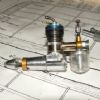
This is my first cam milling setup using a vertical slide. The blank is indexed using a 60 tooth changewheel with a paper degree scale stuck on. The depth of each cut is set using a DTI at the back of the cross slide and the slides are 'locked' with a G clamp. I now do much the same on a milling machine. The maching marks are cleaned up with a swiss file before hardening.
|
| Paul Horth | 15/02/2021 12:02:53 |
| 69 forum posts 18 photos | Thanks to all of you for the encouraging and helpful messages with plenty of useful information. It's still very much a thought experiment for me. I think I would be able to produce a camshaft using the turning jig method, without needing a rotary table, milling machine or a grinder. It is reassuring to see that a decent sized paper disc marked out in degrees is good enough to be practical, though I am surprised that the one inch disc with marker pen lines, shown in the video clip from Andy G. would be precise enough. Some kind of pointer has to be registered to the shaft, to operate this system. The complicated method used by Graham Meek in the link from Diogenes, or that used by Charles Lamont, would be too much too much trouble for me. I understand Jason's point on making the cams in pairs, on the turning jig, which I could case harden, and polish, then mount on the unhardened shaft, though I would need to devise a method to set the angular positions of the pairs relative to each other and to the shaft keyway. With all four cams made together this would be taken care of. The pairs would have to be drilled through after making, then the excess shaft length cut off, before hardening. I could use milling in the vertical slide as shown by Roger B, though this would need a reducing sleeve with two keyways to register the change wheel to the shaft, and 60 teeth would not enable the 130 degree setting for the exhaust cam flanks. But, in principle I could do it. So each method has its pros and cons, with balances of time, effort and precision to be decided. I understand the point about the fit of piston to bore, it has to be much closer than in a steam engine. This is one reason why a diesel engine would not be my choice because this fit has to be even closer than for a four stroke. And not only do I need a close fit, but it has to be dimensionally accurate, to use piston rings as provided in the kit. My aim would be to produce an engine which could run on a table top setup, and, importantly for me, would drive a load which could be regulated. No ideas yet on what would be practical for that. Thinking is a lot easier and quicker than doing!
Paul |
| bernard towers | 15/02/2021 13:30:22 |
| 1221 forum posts 161 photos | Sorry not kept up with the thread but the Westbury jig is in ME 12th July 1962 pages 56/7, if you need copies I will scan and send plus a photo of my jig. Note this is for cam flanks. |
| Roger B | 15/02/2021 15:27:53 |
244 forum posts 105 photos | The method I use mills the cam using a series of tangents so various angles can be used. I set them out on a spread sheet with the angle and depth of cut, ticking each one off when complete. There are various programmes around for generating the steps from the cam data. This engine was built on a minilathe using a vertical slide. I initially used an O ring to seal the piston but later made a cast iron piston ring.
|
| Andy_G | 15/02/2021 19:57:48 |
260 forum posts | Posted by bernard towers on 15/02/2021 13:30:22:
Sorry not kept up with the thread but the Westbury jig is in ME 12th July 1962 pages 56/7, if you need copies I will scan and send plus a photo of my jig. Note this is for cam flanks. Sorry - I thought you were referring to an engine design (My fault!). I'm guessing it is the same one as in the Seal construction article - Link and also the type used in the video above. |
 )
)


Please login to post a reply.
Magazine Locator
Want the latest issue of Model Engineer or Model Engineers' Workshop? Use our magazine locator links to find your nearest stockist!
Sign up to our Newsletter
Sign up to our newsletter and get a free digital issue.
You can unsubscribe at anytime. View our privacy policy at www.mortons.co.uk/privacy
Latest Forum Posts
- *Oct 2023: FORUM MIGRATION TIMELINE*
05/10/2023 07:57:11 - Making ER11 collet chuck
05/10/2023 07:56:24 - What did you do today? 2023
05/10/2023 07:25:01 - Orrery
05/10/2023 06:00:41 - Wera hand-tools
05/10/2023 05:47:07 - New member
05/10/2023 04:40:11 - Problems with external pot on at1 vfd
05/10/2023 00:06:32 - Drain plug
04/10/2023 23:36:17 - digi phase converter for 10 machines.....
04/10/2023 23:13:48 - Winter Storage Of Locomotives
04/10/2023 21:02:11 - More Latest Posts...
- View All Topics
Support Our Partners


Shopping Partners
Subscription Offer

Latest "For Sale" Ads
- Reeves** - Rebuilt Royal Scot by Martin Evans
by John Broughton
£300.00 - BRITANNIA 5" GAUGE James Perrier
by Jon Seabright 1
£2,500.00 - Drill Grinder - for restoration
by Nigel Graham 2
£0.00 - WARCO WM18 MILLING MACHINE
by Alex Chudley
£1,200.00 - MYFORD SUPER 7 LATHE
by Alex Chudley
£2,000.00 - More "For Sale" Ads...
Latest "Wanted" Ads
- D1-3 backplate
by Michael Horley
Price Not Specified - fixed steady for a Colchester bantam mark1 800
by George Jervis
Price Not Specified - lbsc pansy
by JACK SIDEBOTHAM
Price Not Specified - Pratt Burnerd multifit chuck key.
by Tim Riome
Price Not Specified - BANDSAW BLADE WELDER
by HUGH
Price Not Specified - More "Wanted" Ads...
Get In Touch!
Do you want to contact the Model Engineer and Model Engineers' Workshop team?
You can contact us by phone, mail or email about the magazines including becoming a contributor, submitting reader's letters or making queries about articles. You can also get in touch about this website, advertising or other general issues.
Click THIS LINK for full contact details.
For subscription issues please see THIS LINK.
Digital Back Issues


Donate

 Register
 Log-in
Model Engineer Magazine
- Percival Marshall
- M.E. History
- LittleLEC
- M.E. Clock

ME Workshop
- An Adcock
- & Shipley
- Horizontal
- Mill

Subscribe Now
- Great savings
- Delivered to your door

Pre-order your copy!
- Delivered to your doorstep!
- Free UK delivery!
All Forum Topics > Beginners questions > Could I try an IC engine?