Member postings for Andy_G
Here is a list of all the postings Andy_G has made in our forums. Click on a thread name to jump to the thread.
| Thread: Making ER11 collet chuck |
| 03/10/2023 18:44:18 |
Posted by Dell on 03/10/2023 18:33:15:
when I cut the taper in a bit of aluminium using Rocketronics, large end 11mm and 7.5mm small end overall length of 17mm so putting -Z17 and -X1.725 being half the difference between 11 and 7.5 I get 5deg Assuming 1.725 is a typo for 1.75?? 1.75mm over 17mm is 5.88° by my maths. (tan^-1 (1.75/17) ) 8° would be 2.389mm over 17mm ( tan(8° ) x 17mm ) or 11mm down to 6.22mm diameter.
(Only a few more days of smilie ambushes) Edited By Andy_G on 03/10/2023 18:45:13 |
| Thread: Thermocouple readout manual |
| 23/09/2023 08:56:32 |
This listing says the operating range is -50°C to 950°C (950°C = 1769°F)
|
| Thread: Gib Adjusters and the English Language! |
| 21/09/2023 18:10:56 |
Always been 'gib' (as in Gibson) in my experience, apart from a few (American?) you-choob videos. Sticky-up bits of cranes and the triangular sails at the front of boats are 'jibs'. 'Jigabyte' is just plain weird! (Although 'gigawatt' is pronounced 'jigawatt' in the film 'Back to the Future' ) Edited By Andy_G on 21/09/2023 18:11:15 |
| Thread: Milling on a mini lathe |
| 20/09/2023 08:21:57 |
I think the Warco super mini lathe follows the ubiquitous 7X pattern, and therefore has a relatively short travel cross slide without T slots. In order to fit a vertical slide it will be necessary to drill and tap some extra holes in it, either to fit a vertical slide bracket directly or to fit a 'boring table' that can then be drilled to suit whatever slide fittings are necessary. This was my arrangement:
The boring table is secured using the top slide securing bolts / dowel at the front and an extra couple of tapped holes and a dowel at the rear
The fasteners can be accessed with the vertical slide in place so the whole boring table can be removed without disturbing its alignment. FWIW, these are the dimensions of my plate - it was made from a laser cut piece of 12mm thick steel sheet with the surfaces 'as is': (I wouldn't bother with the 3/8 dowel holes again)
I sais that this *was* my arrangement: I have since done away with the adjustable angle bracket to try and make the arrangement more compact and rigid (relative term!). A carriage lock is a must! Although limited, it has its uses:
The cutters are held directly in the spindle using morse taper 'finger' collets and a home made draw bar (suitably long bolt with a simple collar to bear on the rear of the spindle). I also made a handwheel for the leadscrew to give a 'Z' feed:
|
| Thread: Levelling my lathe - a build log |
| 03/09/2023 09:33:17 |
Scrap the idea - Make the bed out of rectangular hollow section (something like 150 x 75 x 6) and fit the bolts from inside the section uo into the existing tapped holes in the lathe feet. It will be lighter and stiffer. |
| Thread: Improving hobby-grade Servos |
| 28/08/2023 15:40:11 |
Posted by John Haine on 28/08/2023 09:34:17:
Andy, I wish you hadn't posted this! Now I'm thinking about upgrading my cnc to use esp32! Sorry about that! (P.S. you also get wifi control...) Just beware that the ESP32 uses 3.3V logic so (usually) needs a buffer/level shifter to reliably drive stepper motor drivers. (Some people get away without.) Cheap level shifters don't work - DAMHIKT. This was my approach, but you may prefer a ready made interface: Edited By Andy_G on 28/08/2023 15:42:30 |
| 27/08/2023 22:14:29 |
Posted by Ady1 on 27/08/2023 19:32:33:
I was really hoping someone had created an easy multi axis software solution for hobbyists
Not sure if this is what you're asking, but the 32bit ports of GRBL will support up to 6 axes (definitely for the first two, and probably for the third. (Open loop still, though.) GRBL_ESP32, although no longer actively supported is *very* compatible with 8 bit GRBL and its senders. Both it and FluidNC can be compiled in the arduino IDE. FluidNC supports software configuration, so you can make machine changes without having to recompile. It will play with many of the Gcode senders, but not my favourite one (Openbuilds Control). GRBL_HAL needs to be compiled in the appropriate IDE - I haven't used it as I can't be bothered to install yet another IDE, and the web based configurator has limited options. GRBL_ESP32 works well for me on a 3 axis machine with the ability to run a second spinde (laser + rotary) and a 4th axis without having to change any firmware or wiring. CAM is the big hurdle for 4+axes. Edit: I should say *cheap* CAM is the big hurdle...
Edited By Andy_G on 27/08/2023 22:18:37 |
| Thread: Help! Excessive machine marks! |
| 27/08/2023 11:39:23 |
Posted by Margaret Trelawny on 27/08/2023 11:23:42:
Any suggestions where I am now going wrong please? Just one: When you finish the cut, back the tool out slightly before returning to your start position. A lot of the marks look like you're winding the tool back over the work without doing this, giving the coarse spiral marks. |
| Thread: What are these for? |
| 26/08/2023 18:49:35 |
Posted by Mark Easingwood on 26/08/2023 12:19:59:
Not sure they are router cutters, but they might well be "slot mortise bits," generally used in the furniture making industry, as opposed to the Joinery manufacturing industry. They could probably be either, but those don't look (to me) like they have end cutting ability that I think a slot morticer would need (but there are probably more types than I know about). M10 internal seems to be used on all sorts of industrial routers (hand or bench), morticers, etc.. Seems common for automated routers for PVC window frame construction. Have a look for 'Rotox' cutters: (Example )
(Other makes using the same fixing are available).
|
| 26/08/2023 09:20:30 |
Internally threaded router bits. Like these |
| Thread: Planimeter |
| 30/07/2023 12:36:56 |
Posted by David Ambrose on 31/12/2022 19:08:23:
There was I thinking that all the steam engine builders here worked out the IHP of their models by fitting an indicator, and using a planimeter to measure the area of the plot on the card to work out the mean effective pressure. I knew I had used one as part of my engineering degree, but was struggling to remember what for - that was it, though: The lab had a large, single cylinder horizontal gas engine with an indicator fitted and we used the planimeter to measue the area of the indicator trace when analysing its performance. Never used one since! |
| Thread: Multiple Bearings in Spindle |
| 29/07/2023 21:14:41 |
Posted by Steve Crow on 29/07/2023 18:22:07:
I don't know the first thing about O-rings by the way. If anyone can enlighten me to what I need for this application? The O-ring isn't particularly critical - find one with an ID that matches the bearing OD (within a few %) and has a section diameter that is less than ~25% of the bearing width. Cut the groove in the housing to ~90% of the O-ring section deep by somewhere between ~125% and ~150% of the O-ring section wide (not critical). The groove is roughly centered on the bearing location. (The groove could be machined in a different setup to machining the bore because any sight lack of concentricity doesn't matter.)
|
| 28/07/2023 23:16:53 |
Posted by Iain Downs on 28/07/2023 19:39:59:
the point of my design is to put it in a collet in a (locked) mill spindle -not much chance of driving that from behind! Sorry, I misunderstood - I read it that you had a separate high speed spindle, offset from the mill spindle, with some sort of mounting bracket held in the mill collet - my apologies. |
| 28/07/2023 18:35:32 |
Posted by Iain Downs on 28/07/2023 16:46:38:
The specific thing I wanted to achieve is to be able to mount the high speed spindle in the mill and have it be correctly registered. I could, for example rough something out with a 10mm end mill and tidy up with a 1mm mill. This kind of works ( drilling with sub 1mm drills is entirely possible now), but the run out is bigger than I'd like. I'm not sure if all the complications of Steve's spindle is really required for what I want. In particular, going mad for rigidity may make little sense if I have a bit sticking out with a drive on it Have you checked the runout of the taper on the ER11 collet extension with respect to its own shaft? I have had a couple of shockingly bad ones and one very good one (roughly similar prices). Similarly, 'cheap' ER11 collets vary widely in their ability to run true. Could you put the drive pulley on the rear of the bearing arrangement so that there was less overhang at the front bearing? IMHO, it's well worth trying to minimise tool overhang, to minimise the effect of spindle runout / lack of straightness. The smaller the tool diameter, the better the runout needs to be. This is the arrangement for a toolpost spindle I made using the good ER11 collet extension. It is driven from the rear by a timing belt pulley:
The motor is mounted piggy-back:
I wouldn't use the double row A/C bearing again (it still needs to be preloaded to remove slop - I didn't realise until after I'd made it). If I were to make one using an ER collet extension holder again, I'd probably use a similar configuration, but with a single bearing at each end (maybe A/C or maybe plain ball bearing, depending on likely loads & budget at the time). I think it would be a compromise compared to machining a spindle to one of the designs above, though. (Sorry, I didn't intend to monopolise this thread - it's just a topic that I have given quite a bit of thought to over the last few years!) Edited By Andy_G on 28/07/2023 18:36:00 |
| 28/07/2023 14:58:29 |
Posted by Michael Gilligan on 28/07/2023 13:42:18:.
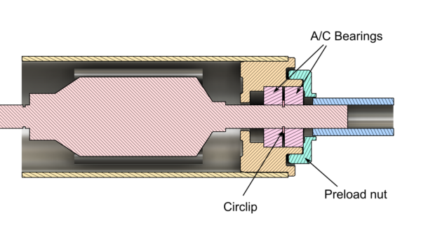
If the housing was made from Machinable Technical Ceramic, the effect of warming should be to reduce the preload … making the device “fail-safe” The problem I had with the aluminium housing was that the preload reduced / disappeared when it got warm. If the preload was adjusted to 'take the slack out' in this condition, then the spindle almost seized when it cooled down. This was with a solid spacer between the inner races (a circlip for various reasons) and an adjustable nut to preload the outer races against each other:
Unless I'm missing something, the same arrangement with a [low expansion] ceramic housing would do the opposite: i.e. preload would tighten up as the temperature increases. Incidentally, something to consider is that matched pairs of angular contact bearings suitable for face to face mounting are available, fairly cheaply, as spare parts for Chinese made CNC router spindles. Face to face mounting takes the expansion of the housing out of the equation. The quality of the ones that I have bought has been pretty good. Edited By Andy_G on 28/07/2023 15:00:04 |
| Thread: Miltary Database? |
| 28/07/2023 14:39:14 |
Posted by Martin King 2 on 28/07/2023 14:11:39:
someone I may have to deal with on something important, just sounds “off” somehow. Martin
Doesn't run a bicycle repair shop on Anglesey, does he? He used to be a General Manager at a place where I used to work.Technically, he was in the Royal Marines, but never made it through basic training. Didn't stop him regaling people with his gruesome tales of daring-do and unfeasible feats (it turned out that Len Deighton must have been with him for most of them). Completely brazen / psychopathic personality. I don't think there's any public record that can be used to verify this sort of thing (we looked very hard once suspicions were aroused). A real ex-RM knew through his contact that this person was a Walter Mitty, and in the end 'whistle-blew' to our mutual employer. The employer responded by disciplining the whistle-blower for breaching confidentiality! Walter Mitty was also disciplined, but not sacked! It's a funny old world...
|
| Thread: Multiple Bearings in Spindle |
| 27/07/2023 10:34:49 |
Posted by Kiwi Bloke on 27/07/2023 02:29:27: ...the machining of the housing, to get the bearing housings aligned, is not a trivial job...
This is a powerful argument (in my mind, at least) for making the tail bearing OD smaller as it allows all of the bearing locations in the housing to be machined in the same operation, giving the best concentricity possible with given equipment. (They don't need to be *especially* accurate otherwise - the tail bearing bore is probably the most critical: to allow float without slop.) I'm not sure what material Steve is thinking of for the housing, but in the design with a spacer between the inner races only, I would suggest that the housing be made of steel, rather than aluminium, in order to avoid variations in bearing preload as the spindle warms up - I tried something similar with an aluminium housing and the temperature effect was remarkably noticeable. This will be the Rolls Royce of spindles when it's done! |
| 26/07/2023 21:19:50 |
Posted by Iain Downs on 26/07/2023 16:53:13:
I'm particularly interested in how you plan to machine the spindle, Steve. It looks to me like a challenging level of precision for a mini-lathe. Certainly beyond what I think I could achieve.
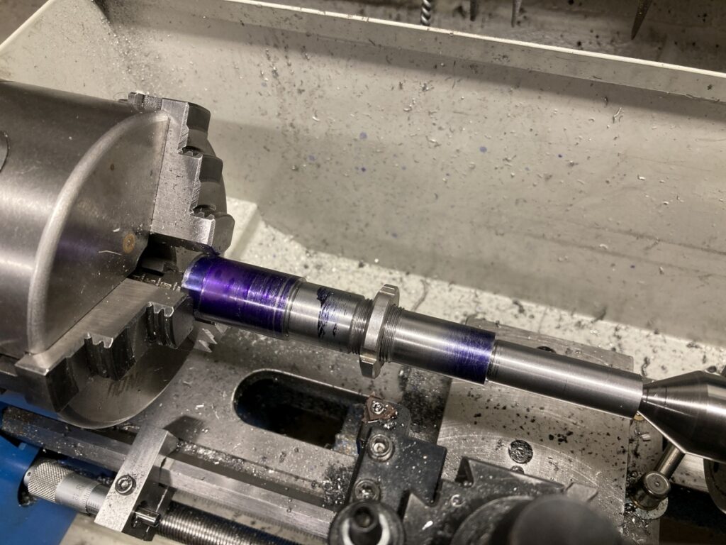
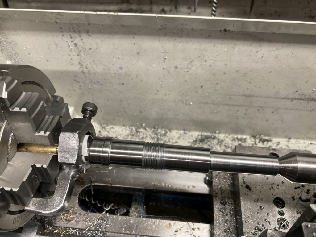
I made an ER11 spindle of a very similar design on my mini lathe. I was very pleased with the way that it came out – I couldn’t detect any runout in the spindle itself with an 0.002mm indicator, and about 4µm TIR on a tool in a decent quality collet. This was the sequence I used: With the stock held in a 3 jaw chuck, I machined the tail end as far as I could and cut the threads for the nose bearing clamp nuts (on my design), but only roughed the bearing journals.
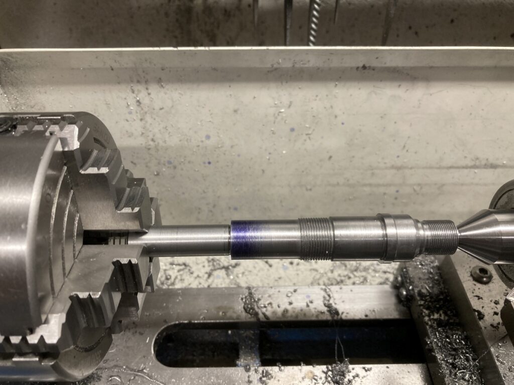
I then flipped the part around and held the tail end (centred) in the 4 jaw chuck. The other end was supported with a fixed steady while it was centre drilled so I could use a live centre for support while machining the outside of the collet chuck and cutting the collet nut threads.
I used the fixed steady again, without disturbing the part, to bore the collet recess and cut the internal taper for the collet. That was the bulk of the machining completed.
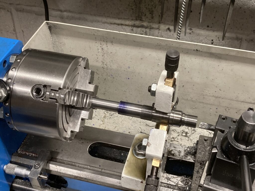
I then chucked a short piece of brass and cut it to match the collet taper (while the compound slide was set to the correct ER taper angle). I could then mount the spindle between centres, using the collet taper to support the ‘nose’ end of the spindle on the brass live centre with a dead centre in the tailstock. This setup was used to machine the bearing abutments and journals.
The journals were left 0.01mm oversize and then lapped to final size. I was very pleased that I managed to get them both pretty much spot on – just a few microns above nominal. There's a bit more description of the whole thing on the page I linked to in a previous post. I'm sure that there are other ways of doing it, but that's what worked for me. |
| 25/07/2023 15:24:24 |
Posted by Steve Crow on 25/07/2023 10:03:00:
I may well be incorporating the rear nut into the pulley yet. That way won't the torque keep the nut locked? Yes - my comments would only apply to the case where you have a nut retaining the bearing only (the design in the post on 24/7 15:02). For the latest iteration, I don't see much point in threading the pulley *and* fitting locknut. As you say, the drive torque will keep things done up. |
| 25/07/2023 09:58:01 |
Posted by Nick Wheeler on 25/07/2023 09:45:12:
I'd be more concerned about the M7 nut on the other end. That nut can be done up tight, but it should be left hand thread for a clockwise spindle by rights (or backed up by a locknut). I think that the concern for the front clamp ring is because it will be used to set the bearing preload, so will need to be locked at the chosen position, rather than being done up tight. Edited By Andy_G on 25/07/2023 10:01:17 |


Magazine Locator
Want the latest issue of Model Engineer or Model Engineers' Workshop? Use our magazine locator links to find your nearest stockist!
Sign up to our Newsletter
Sign up to our newsletter and get a free digital issue.
You can unsubscribe at anytime. View our privacy policy at www.mortons.co.uk/privacy
Latest Forum Posts
- *Oct 2023: FORUM MIGRATION TIMELINE*
05/10/2023 07:57:11 - Making ER11 collet chuck
05/10/2023 07:56:24 - What did you do today? 2023
05/10/2023 07:25:01 - Orrery
05/10/2023 06:00:41 - Wera hand-tools
05/10/2023 05:47:07 - New member
05/10/2023 04:40:11 - Problems with external pot on at1 vfd
05/10/2023 00:06:32 - Drain plug
04/10/2023 23:36:17 - digi phase converter for 10 machines.....
04/10/2023 23:13:48 - Winter Storage Of Locomotives
04/10/2023 21:02:11 - More Latest Posts...
- View All Topics
Support Our Partners


Shopping Partners
Subscription Offer

Latest "For Sale" Ads
- Reeves** - Rebuilt Royal Scot by Martin Evans
by John Broughton
£300.00 - BRITANNIA 5" GAUGE James Perrier
by Jon Seabright 1
£2,500.00 - Drill Grinder - for restoration
by Nigel Graham 2
£0.00 - WARCO WM18 MILLING MACHINE
by Alex Chudley
£1,200.00 - MYFORD SUPER 7 LATHE
by Alex Chudley
£2,000.00 - More "For Sale" Ads...
Latest "Wanted" Ads
- D1-3 backplate
by Michael Horley
Price Not Specified - fixed steady for a Colchester bantam mark1 800
by George Jervis
Price Not Specified - lbsc pansy
by JACK SIDEBOTHAM
Price Not Specified - Pratt Burnerd multifit chuck key.
by Tim Riome
Price Not Specified - BANDSAW BLADE WELDER
by HUGH
Price Not Specified - More "Wanted" Ads...
Get In Touch!
Do you want to contact the Model Engineer and Model Engineers' Workshop team?
You can contact us by phone, mail or email about the magazines including becoming a contributor, submitting reader's letters or making queries about articles. You can also get in touch about this website, advertising or other general issues.
Click THIS LINK for full contact details.
For subscription issues please see THIS LINK.
Digital Back Issues


Donate

 Register
 Log-in
Model Engineer Magazine
- Percival Marshall
- M.E. History
- LittleLEC
- M.E. Clock

ME Workshop
- An Adcock
- & Shipley
- Horizontal
- Mill

Subscribe Now
- Great savings
- Delivered to your door

Pre-order your copy!
- Delivered to your doorstep!
- Free UK delivery!