Forum sponsored by:

Harold Hall basic grinding rest
Looking for feedback building and using
| derek hall 1 | 27/06/2020 15:43:03 |
| 322 forum posts | Hi everyone I am looking at building the simple grinding rest by Harold Hall, as opposed to the more involved and longer to build advanced version. So my question is how did the build go and how are you finding it during use? Although the advance version looks more versatile I have looked at both designs and the simple version seems to do all that I want such as grinding lathe tools etc Looking forward to your replies Regards to all Derek |
| john halfpenny | 27/06/2020 15:52:48 |
| 314 forum posts 28 photos | I built the simple version. It's surprisingly (to me) rigid in use, and does my lathe tools and pointy bits well. Not difficult to make as my first project, some 40 years after leaving the apprentice school machine shop.
|
| AdrianR | 27/06/2020 17:10:06 |
| 613 forum posts 39 photos | I have just started on making the simple rest too, good to hear it is rigid. I was a little worried if I had made the right choice. But I thought, my grinder has two wheels, I can always use it on the rough end and make an advanced rest for the fine end. Adrian |
| john halfpenny | 27/06/2020 18:44:46 |
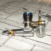
| 314 forum posts 28 photos | Here is mine. The two items in the foreground |
| Danny M2Z | 28/06/2020 03:30:56 |
 963 forum posts 2 photos | I made my version about ten years ago and it's had regular use for producing the cutting edges on lathe tools and sharpening end mills. I had didfficulty locating the plastic ball so used a donated steering ball joint. This had the advantage of a spigot and might last longer than the plastic ball. I keep a soft brush nearby as the grinding dust gets everywhere. For that reason I do not use oil for the sliding/pivotting parts, powdered graphite works ok. * Danny M *
|
| derek hall 1 | 28/06/2020 07:12:33 |
| 322 forum posts | Thanks guys for your replies. Great photos and really useful information . As I have an 8 inch grinder I will have to do a few mods to the height. Regarding this, is the height measured from the table to the base to coincide with the centre line of the grinder? or is near enough ok? I am also going to fit a cup wheel instead of the normal straight wheel. Yet another job i am going to do is to use the method by "stub mandrel" on this site to modify the way the wheels are mounted on the spindle - currently it uses a 1mm step on the shaft to ensure that an 8 inch grinding wheel runs true! Something similar was recommended by Harold in his book "Tool and cutter sharpening". What a great forum this is, so much help and information....! Regards Derek
|
| Alfie Peacock | 28/06/2020 11:36:45 |
| 55 forum posts 1 photos | Looking at the two rests the basic looks quite easy to make, with the accessories for end mill cutting on the basic rest would results be acceptable, as for the advanced rest a lot more work and material and dove tail cutter is needed.. The advanced rest looks more up for the job but I just want things to be a bit more simple to make and have a tool for grinding a end mill, the photos show these accessories so why make the advanced rest. Alfie |
| Jager | 28/06/2020 21:04:20 |
| 44 forum posts 5 photos | Good Evening, I made the simple rest some time ago and offer the following observations: 1. - Be sure to be accurate and precise in component fit. 2 - Use only good quality, tightly toleranced taps, dies and drills. Any thing less and you will have imprecise movements and backlash 3. - Fit an adjustable gibb in the in-feed dovetails. 4. - If you are left handed put the traverse locking screw on the left side. 5. - As I use the rest both in the front and at the side of the grinder I find relocating it a chore and often its position is just not quite right. I am overcoming this by fixing a mild steel plate to the bench, doing away with the rest hold- down fixings and fitting two magnetic clamps to the base. 6. - I find the adjustment of the drill sharpening jig backstop fussy, so have drilled and tapped an M5 hole through the vertical part of the drill backstop. It is located at the horizontal centreline of the backstop and level with the bottom of the vee groove. through this I have fitted a screwed rod with a 20mm dia x 5mm longbrass thumbscrew on each end. This enables precise longitudinal positioning of drills of varying length without recourse to fiddling (arnt I polite?) about with the backstop adjustment. I had considered building the improved version of the rest but find my improvements work well and doubt if the posh version is any better, In some ways its' parallellogram adjustment is an unnecessary complication - but I stand to be corrected by my peers!
|
| Neil Wyatt | 28/06/2020 21:13:36 |
 19226 forum posts 749 photos 86 articles | I think others have gone the way of a magnetic hold down. Forces involved in grinding shouldn't be too great, much less than those involved in milling and turning. In case anyone is reading this and wondering where to find the plans, see out the latest issues of MEW 294 and 295 which reprint the basic rest and main accessories. Neil |
| David Caunt | 28/06/2020 22:05:59 |
 110 forum posts 40 photos | Derek I built this rest about 4 years ago and am quite happy with it other than there is a tendency for the table to rotate as it is only relying on the friction of the countersunk screw holding the table to the plastic ball to stop it. Otherwise it work well. Having now made Harold's Mill sharpening holder I've now got to make a vertical sliding mount for the grinder. It is typical the one thing always leads to another.
Dave |
| derek hall 1 | 29/06/2020 06:38:19 |
| 322 forum posts | Thanks again for your replies. Magnetic hold down method similar to the advanced version seems the way to go to add a bit of versatility. Regarding the table moving as it's only relying on the plastic ball and one countersunk screw is an excellent point, I wonder if the problem exists if the ball is metal as in Danny's example. I guess any design has areas for improvement Regards Derek |
| Jager | 29/06/2020 09:06:41 |
| 44 forum posts 5 photos | Hi there David and Derek, I have had no problems with the ball which I loctited to the bolt. It does need to be kranked pretty tight though between the countersunk clamp plates. If it eventually gives problems, which I somehow doubt, I will simply make either two sets of hinges disposed 90 degrees and capable of being adjusted by a long reach allen key or, if I ever get round to making a ball-turner, fit a purpose made Noga type adjustment as used on dial indicators. Derek, may I ask the purpose of the vertical sliding mount? Regards, Jager |
| Danny M2Z | 29/06/2020 09:14:56 |
963 forum posts 2 photos | Posted by derek hall 1 on 29/06/2020 06:38:19:I wonder if the problem exists if the ball is metal as in Danny's example.
My table has never moved during use. As Neil pointed out, the grinding forces are small. The mounting board has two threaded inserts so that the rest can be fixed repeatably in the same position. If you noticed the protruding bolt to the right of my grinder that is for the drill sharpener (same reason). The metal ball was from a friend who's son managed to crash his car so might be easy to pick one up from a car wrecking yard. The spigot was a useful bonus. Magnetic mounting seems nice but how does one assure positioning repeatability and what happens if the tool being ground digs into the grinding wheel? * Danny M * |
| john halfpenny | 29/06/2020 13:08:37 |
| 314 forum posts 28 photos | Likewise, I used nut inserts, and my picture shows the base of my drill grinding jig. No movement in use with plastic ball, which is what initially surprised me. |
| Cabinet Enforcer | 29/06/2020 13:18:17 |
| 121 forum posts 4 photos | Posted by Neil Wyatt on 28/06/2020 21:13:36:
I think others have gone the way of a magnetic hold down. Forces involved in grinding shouldn't be too great, much less than those involved in milling and turning. In case anyone is reading this and wondering where to find the plans, see out the latest issues of MEW 294 and 295 which reprint the basic rest and main accessories. Neil Colour me confused Neil, but the reprint is of the advanced rest not the basic one? |
| Jager | 29/06/2020 13:26:26 |
| 44 forum posts 5 photos | I have been using nut inserts for two differing positions but I find at times when grinding four facet drill bits that whilst setting the jig for the first 2 facets with the table close to the wheel side, declined at 30 degrees, and then swinging the table to the 10 degree position to grind the second facets it is necessary to move the table back to clear the wheel. At present I do this by using the rest adjustment on the angle base as it is not always possible to gain sufficient movement on the in-feed depending on the length of drill being not sufficient to hang it out. It is for this reason I want a ready means of repositioning and the mag bases will give me an endless sufficiency. A number of lines scribed on the bench mounted plate will provide positioning guides whilst two mag bases each with a pull of 80 kg will prevent unwanted movement. |
| David Caunt | 29/06/2020 16:00:49 |
110 forum posts 40 photos | Jager. I think you mean't to ask me re the vertical sliding mount. With the mill sharpening holder on the table the end of the mill is so high on the wheel that I need to raise the grinder. It will come in handy anyway.
David |
| Cabinet Enforcer | 29/06/2020 16:37:27 |
| 121 forum posts 4 photos | Posted by Cabinet Enforcer on 29/06/2020 13:18:17:
Posted by Neil Wyatt on 28/06/2020 21:13:36:
I think others have gone the way of a magnetic hold down. Forces involved in grinding shouldn't be too great, much less than those involved in milling and turning. In case anyone is reading this and wondering where to find the plans, see out the latest issues of MEW 294 and 295 which reprint the basic rest and main accessories. Neil Colour me confused Neil, but the reprint is of the advanced rest not the basic one? Correcting myself here, the index said p62, and when checking the online copy I found it at p20, could I heck find it in the printed copy earlier this month, but looking now it seems to have snuck in there |


Please login to post a reply.
Magazine Locator
Want the latest issue of Model Engineer or Model Engineers' Workshop? Use our magazine locator links to find your nearest stockist!
Sign up to our Newsletter
Sign up to our newsletter and get a free digital issue.
You can unsubscribe at anytime. View our privacy policy at www.mortons.co.uk/privacy
Latest Forum Posts
- *Oct 2023: FORUM MIGRATION TIMELINE*
05/10/2023 07:57:11 - Making ER11 collet chuck
05/10/2023 07:56:24 - What did you do today? 2023
05/10/2023 07:25:01 - Orrery
05/10/2023 06:00:41 - Wera hand-tools
05/10/2023 05:47:07 - New member
05/10/2023 04:40:11 - Problems with external pot on at1 vfd
05/10/2023 00:06:32 - Drain plug
04/10/2023 23:36:17 - digi phase converter for 10 machines.....
04/10/2023 23:13:48 - Winter Storage Of Locomotives
04/10/2023 21:02:11 - More Latest Posts...
- View All Topics
Support Our Partners


Shopping Partners
Subscription Offer

Latest "For Sale" Ads
- Reeves** - Rebuilt Royal Scot by Martin Evans
by John Broughton
£300.00 - BRITANNIA 5" GAUGE James Perrier
by Jon Seabright 1
£2,500.00 - Drill Grinder - for restoration
by Nigel Graham 2
£0.00 - WARCO WM18 MILLING MACHINE
by Alex Chudley
£1,200.00 - MYFORD SUPER 7 LATHE
by Alex Chudley
£2,000.00 - More "For Sale" Ads...
Latest "Wanted" Ads
- D1-3 backplate
by Michael Horley
Price Not Specified - fixed steady for a Colchester bantam mark1 800
by George Jervis
Price Not Specified - lbsc pansy
by JACK SIDEBOTHAM
Price Not Specified - Pratt Burnerd multifit chuck key.
by Tim Riome
Price Not Specified - BANDSAW BLADE WELDER
by HUGH
Price Not Specified - More "Wanted" Ads...
Get In Touch!
Do you want to contact the Model Engineer and Model Engineers' Workshop team?
You can contact us by phone, mail or email about the magazines including becoming a contributor, submitting reader's letters or making queries about articles. You can also get in touch about this website, advertising or other general issues.
Click THIS LINK for full contact details.
For subscription issues please see THIS LINK.
Digital Back Issues


Donate

 Register
 Log-in
Model Engineer Magazine
- Percival Marshall
- M.E. History
- LittleLEC
- M.E. Clock

ME Workshop
- An Adcock
- & Shipley
- Horizontal
- Mill

Subscribe Now
- Great savings
- Delivered to your door

Pre-order your copy!
- Delivered to your doorstep!
- Free UK delivery!
All Forum Topics > Workshop Tools and Tooling > Harold Hall basic grinding rest