Forum sponsored by:

Stuart 10V Build Log - Complete Beginner...
| Dr_GMJN | 10/05/2020 19:28:37 |
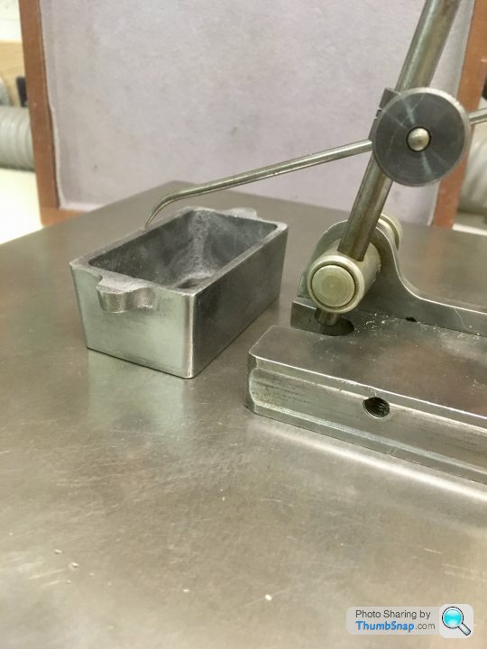
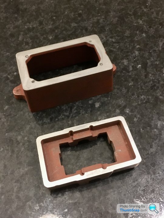
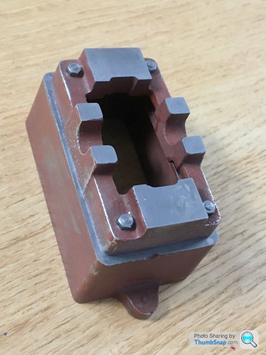
 1602 forum posts | Hello All. I am a complete novice, so this will not be a step-by-step account of building a Stuart 10V; there are plently of books, threads and videos out there already. I hope that what I post will promp some much needed advice. I will make mistakes, but I will get there in the end. This is the begining of what will inevitably be a long journey for me. I have a Myford ML7 which I restored about 12 years ago, but have only done simple jobs with it. I bought an SX2P mini mill last Septemebr, and have mildy tweaked it with some common upgrades over the past few weeks. I am in the process of making some vice clamps for it - the first things I've ever milled (not counting some workshop practice at university many years ago). I have always liked scale model building, and steam engines, so I bought this kit at the Doncaster show last year, and vowed to make a start within a year. Today was the anniversary of getting the kit, so I made a start. Despite getting excellent advice over the past few days from the "Beginners" section on here, I’m still not confident enough to use the milling machine on a casting; I want to try different tooling and techniques first, on the remaining two vice clamps. Anyway, first job was cleaning up the box base and sole plate casting using files, and abrasive paper on a surface plate: I'm waiting for some end mills and a fly cutter, which I'll try out on the remaining two vice clamps. Hopefully then I will have enough courage to try a casting. Cheers! |
| Thor 🇳🇴 | 11/05/2020 06:10:15 |
 1766 forum posts 46 photos | You have made a good start, good luck with the rest of your build. I usually use a carbide tipped mill to remove any hard spots before taking a finishing cut with a HSS tool. Thor |
| Brian H | 11/05/2020 06:31:32 |
 2312 forum posts 112 photos | Looking good! I agree with Thor about using a carbide milling cutter although I had no problems with Stuart castings having hard spots, once the surface with any sand still present had been removed. Traditionally this is done with worn files, worn because you don't want to damage good files. Brian
|
| Dr_GMJN | 11/05/2020 08:07:27 |
1602 forum posts | Thanks Thor and Brian. Re. The carbide tooling: I don’t have an insert milling cutter yet, but have an 8mm DCMT holder and inserts. I’ve got a fly cutter on order, so I was going to try that combination. Also got some end mills on order, so could try finishing with one of those. |
| Dr_GMJN | 11/05/2020 08:16:05 |
1602 forum posts | I had another look at the Smith/Pengwern book on the 10V: There is a drawing of the box bed in there with a height shown (28mm 1 1/8&rdquo |
| Dr_GMJN | 13/05/2020 23:04:48 |
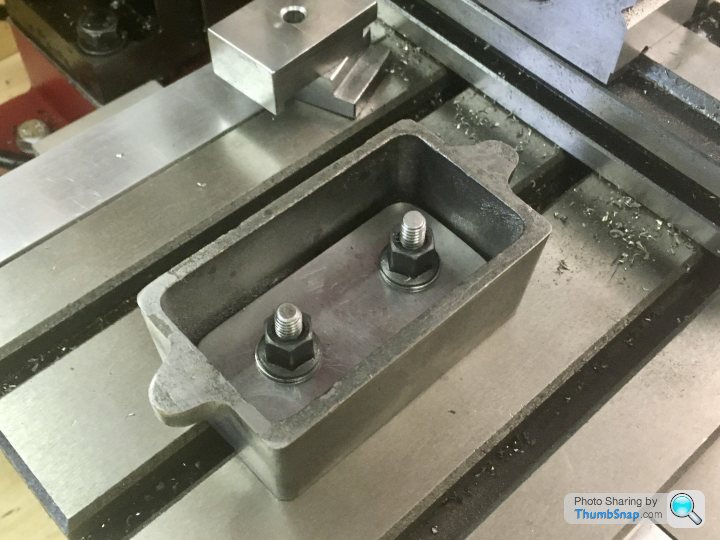
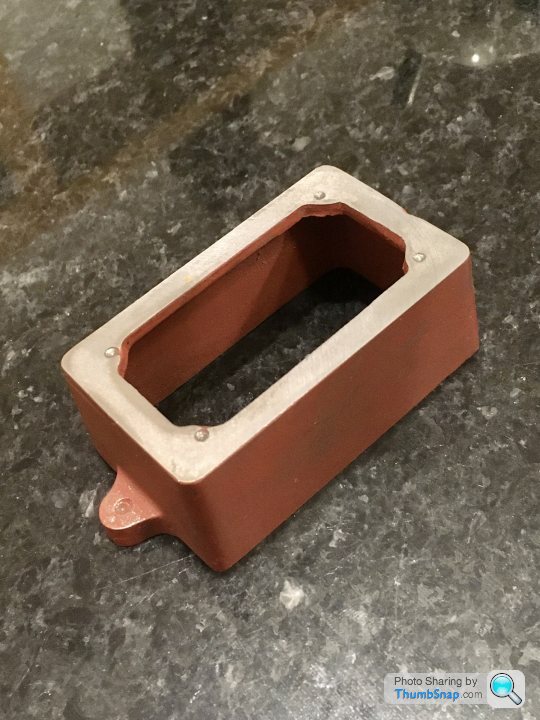
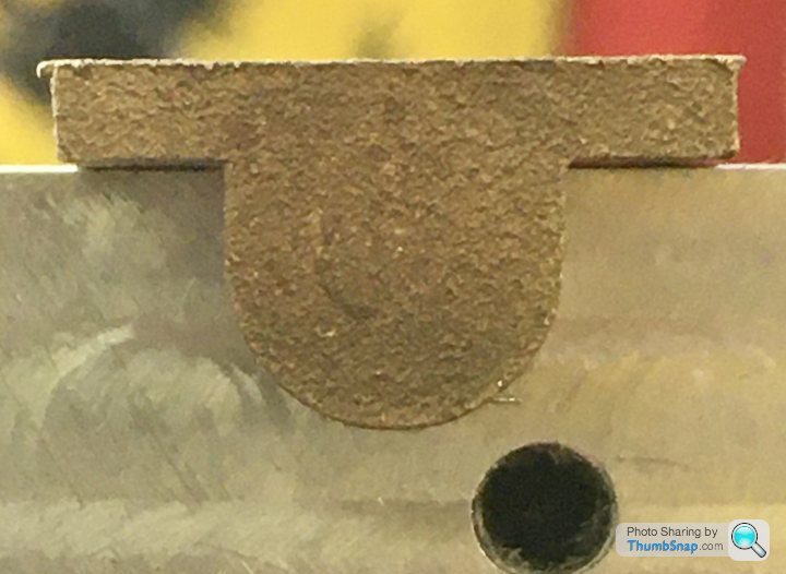
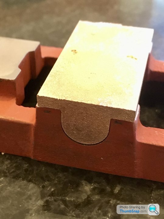
1602 forum posts | Finally took the plunge and machined my first casting. Nothing spectacular, but it feels like a big step for me. I opted to use the fly cutter with an insert for cast iron, mainly because it's by far the best method I've used for getting a good finish. I used my fixture plate for one side, and the remaining two vice clamps (finished this evening) for the other. There's no height specified on the drawing, so I just did the mimimum clean-up. I think the different colours through the wall must be something to do with how the metal cooled: |
| JasonB | 14/05/2020 07:01:01 |
 25215 forum posts 3105 photos 1 articles | It is not a critical height so they don't give it, holes best placed to look right, best drawings I have seen on this type of thing had "COB" on the which equates to Centre on boss. Back in the day when this was likely to have been filed to finish you did not want to file more than needed. Good job you went at it with crabide, that bright shiny edge to the underside is where the casting has some chill (hard) as the edge/corners have cooled quickly, there there is more mass in the mounting lugs it has cooled slower so you have got the matt (soft) finish Leave the 4 holes in the top until you have done the base and then drill them to match. Edited By JasonB on 14/05/2020 07:02:01 |
| Dr_GMJN | 14/05/2020 14:29:51 |
1602 forum posts | Posted by JasonB on 14/05/2020 07:01:01:
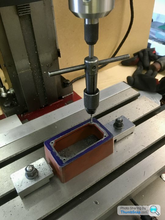
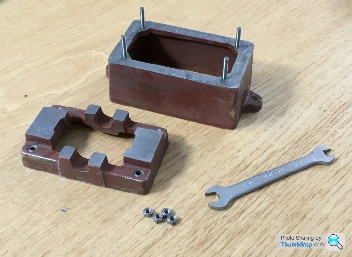
It is not a critical height so they don't give it, holes best placed to look right, best drawings I have seen on this type of thing had "COB" on the which equates to Centre on boss. Back in the day when this was likely to have been filed to finish you did not want to file more than needed. Good job you went at it with crabide, that bright shiny edge to the underside is where the casting has some chill (hard) as the edge/corners have cooled quickly, there there is more mass in the mounting lugs it has cooled slower so you have got the matt (soft) finish Leave the 4 holes in the top until you have done the base and then drill them to match. Edited By JasonB on 14/05/2020 07:02:01 Jason, My plan was to align the sole plate centrally - by eye - on the box bed - after all I want as equal gaps as possible all around, and I assume doing this by eye on castings like these is as good as any other method? I might put a few spots of pva on the joint so I can move them around together for aligning the sole plate on the mill table. I'll confirm I've got a best fit in x & y by putting a pointer in the chuck and moving it along the casting edges and bearing features, then center it to 0,0 in the middle of the piece using the DRO's. Then I can take co-ordinates for drilling the corner holes. Then clamp together and drill the 7BA tapping holes straight through both parts. Then open up the sole plate holes only to 7BA clearance, and spot-face. I'll use the head vertical hard stop to make sure there are no screw ups with depth. Then remove the base and tap the box bed. I think I may need to displace the holes outwards slightly to get a clean spot face, but If I note the drilling co-ordinates from the DRO's it shouldn't be an issue. Cheers.
|
| Dr_GMJN | 14/05/2020 22:45:27 |
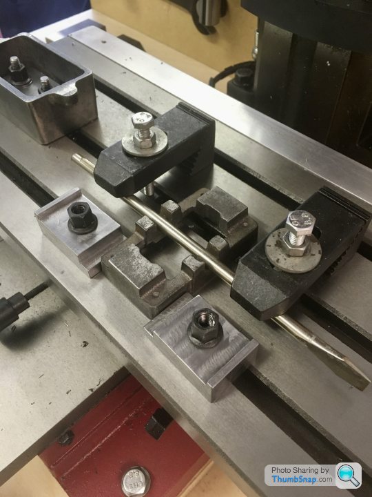
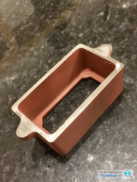
1602 forum posts | Got the sole plate faced tonight - I used the fly cutter again for the top, and took about 0.35mm off: |
| Jon Cameron | 14/05/2020 23:09:35 |
| 368 forum posts 122 photos | If you drill through the top bearing plate with a tapping size drill, then use supeglue to temporarily hold the parts together, so you can mark the centres by running the tapping size drill through the hole held with finger and thumb. Which will leave a small centre for you to drill through and tap. The top plate can then be drilled through at clearance size and the holes will marry up lovely. (Or that's the plan) superglue breaks it's bolt with heat so a quick blast with a small torch will have the two halves separated. Hope this helps. |
| Dr_GMJN | 15/05/2020 00:37:23 |
1602 forum posts | Posted by Jon Cameron on 14/05/2020 23:09:35:
If you drill through the top bearing plate with a tapping size drill, then use supeglue to temporarily hold the parts together, so you can mark the centres by running the tapping size drill through the hole held with finger and thumb. Which will leave a small centre for you to drill through and tap. The top plate can then be drilled through at clearance size and the holes will marry up lovely. (Or that's the plan) superglue breaks it's bolt with heat so a quick blast with a small torch will have the two halves separated. Hope this helps. Thanks Jon, that’s pretty much what I outlined two posts up, the difference being using PVA (releases with water) and clamping both parts together to the bed, drilling both simultaneously with the tapping drill, and then just the sole plate (depth stop on the head) with the clearance drill. |
| Dr_GMJN | 15/05/2020 20:26:23 |
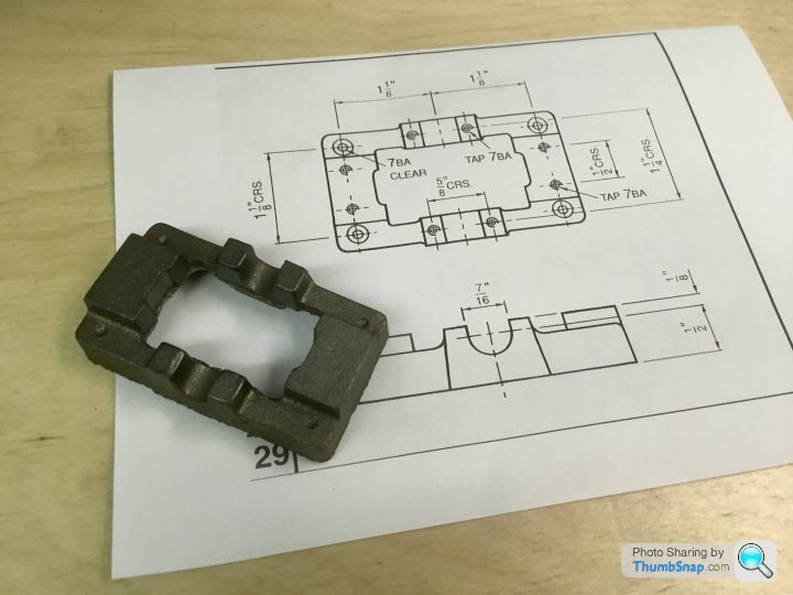
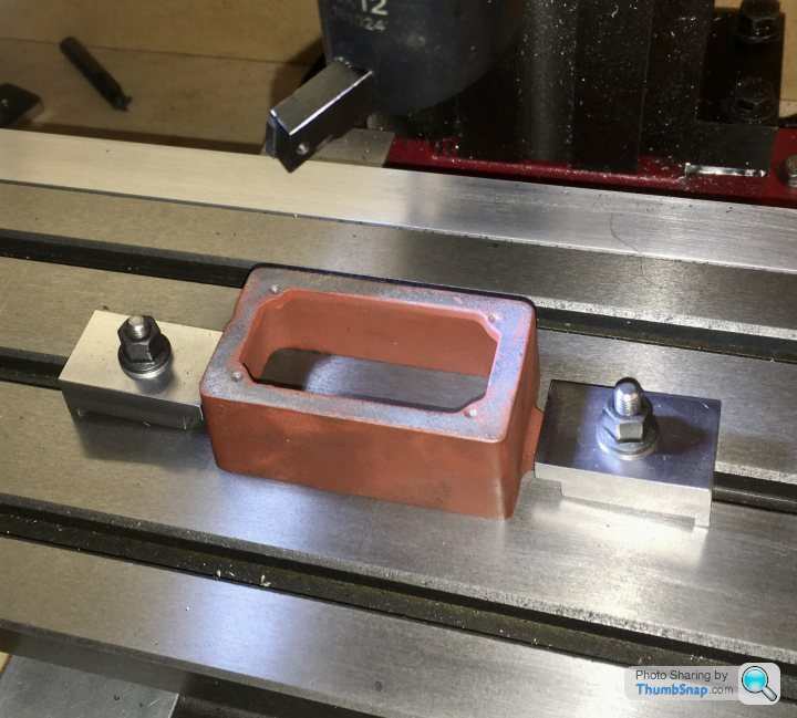
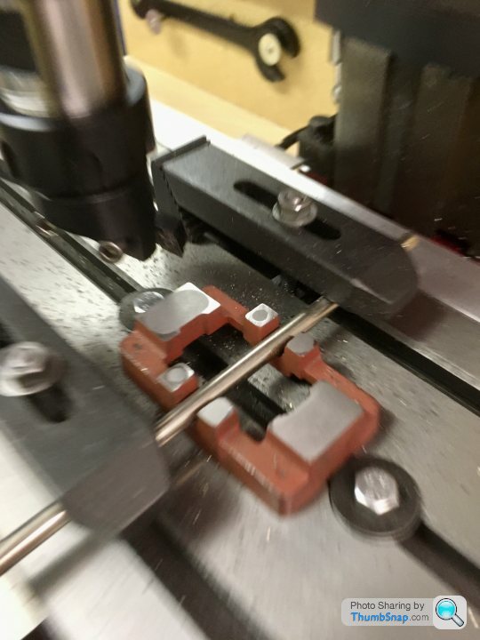
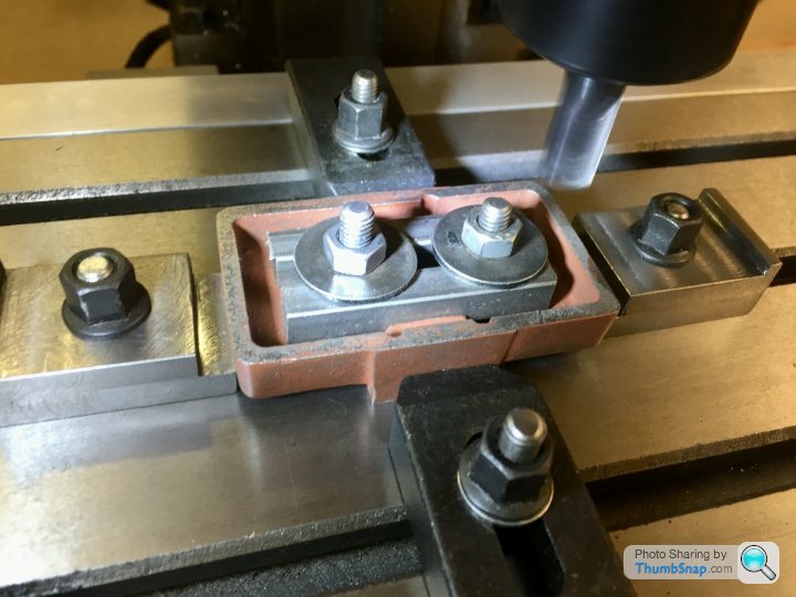
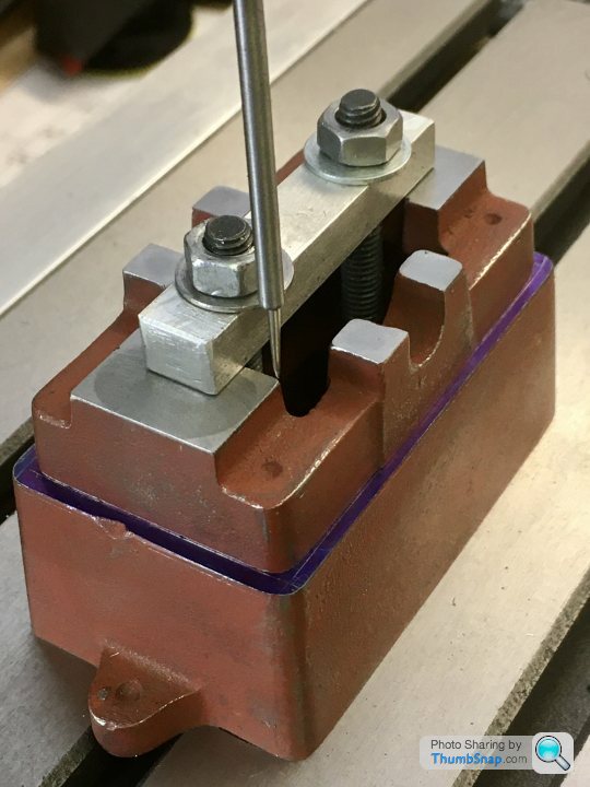
1602 forum posts | So I set up the box bed and sole plate on the table and best-fit aligned it in x & y using a pointed wiggler and edge finder. I'd already marked out the best-fit outline of the sole plate on the box bed top surface: |
| Dr_GMJN | 21/05/2020 18:19:25 |
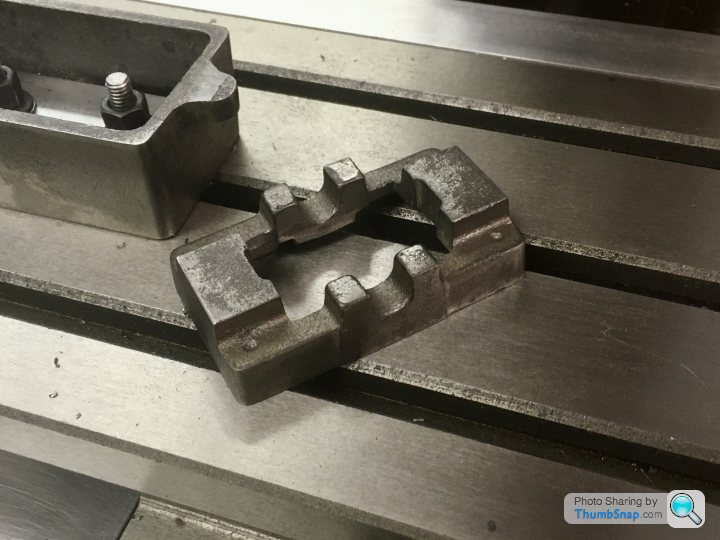
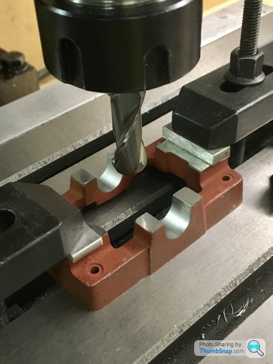
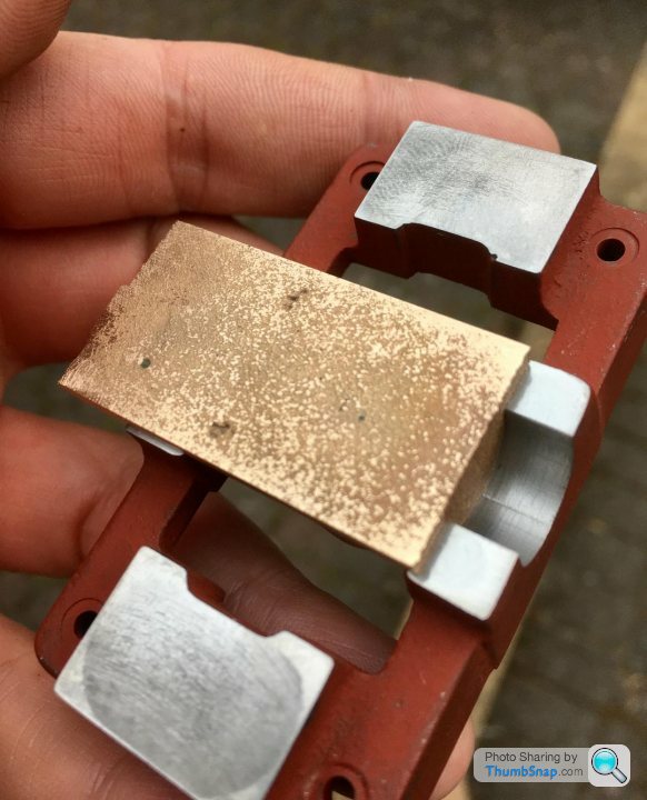
1602 forum posts | So after the false start trying to mill the main bearing recesses with the wrong tool, I tried again with a slightly smaller one ( 11mm, not 7/16" ). Tested in aluminium: Edited By Dr_GMJN on 21/05/2020 18:19:55 |
| SillyOldDuffer | 21/05/2020 18:33:41 |
| 10668 forum posts 2415 photos | Cooking on Gas now! Good job. Dave |
| JasonB | 21/05/2020 19:05:55 |
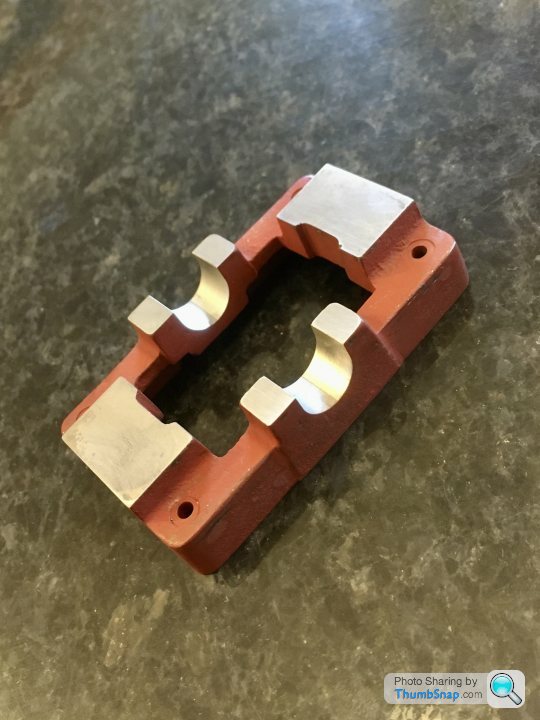
25215 forum posts 3105 photos 1 articles | looks Good Interesting to see your bearing material, it looks a lot more like a gun metal casting than the usual brass extrusion going by texture, even colour but that may be the camera, I wonder if they have changed materials, is it a recently bought kit? |
| Dr_GMJN | 21/05/2020 21:00:11 |
1602 forum posts | I got the kit a year ago from Stuat Models at the Doncaster show. Pretty sure it's cast brass:
|
| Dr_GMJN | 21/05/2020 21:00:59 |
1602 forum posts | Posted by SillyOldDuffer on 21/05/2020 18:33:41:
Cooking on Gas now! Good job. Dave Thanks Dave. Yes, It'll be done this time tomorrow at this rate! |
| Lainchy | 21/05/2020 21:43:11 |
 273 forum posts 103 photos | Following this, and making great job of it. I found Andrew Whales youtube build very useful for my S50, and I know he's done one for the 10v too. He's also a forum member. I know he had some pitfalls with the column and crosshead guide.... but it's well worth watching. https://www.youtube.com/playlist?list=PLxJNoWSqCTFjyUJIklaYuWL0lgTXlq-Pb
|
| paul rayner | 21/05/2020 22:02:47 |
| 187 forum posts 46 photos | have a look at Harold Halls site he has a build log for the 10v with lots of useful tips and plans for work holding jigs etc. regards Paul
|
| Mark Gould 1 | 21/05/2020 22:30:07 |
| 231 forum posts 131 photos | Your progress looks excellent! I did started my first Stuarts 2 years ago and have only just completed it. Go slow and it'll turn out beautifully. You seem to know what you're doing so no worries there Mark |
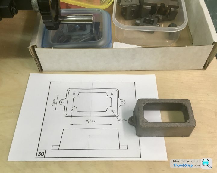

 , but no height dimension is on the drawings I got with the kit. Also, there is no centre distance given for the base lugs. I guess it doesn’t really matter for this part, but I think it would have been good practice to either dimension the height and centres, or at least put a note on the drawing; they still need machining, and how much ink did they actually save?


Please login to post a reply.
Magazine Locator
Want the latest issue of Model Engineer or Model Engineers' Workshop? Use our magazine locator links to find your nearest stockist!
Sign up to our Newsletter
Sign up to our newsletter and get a free digital issue.
You can unsubscribe at anytime. View our privacy policy at www.mortons.co.uk/privacy
Latest Forum Posts
- *Oct 2023: FORUM MIGRATION TIMELINE*
05/10/2023 07:57:11 - Making ER11 collet chuck
05/10/2023 07:56:24 - What did you do today? 2023
05/10/2023 07:25:01 - Orrery
05/10/2023 06:00:41 - Wera hand-tools
05/10/2023 05:47:07 - New member
05/10/2023 04:40:11 - Problems with external pot on at1 vfd
05/10/2023 00:06:32 - Drain plug
04/10/2023 23:36:17 - digi phase converter for 10 machines.....
04/10/2023 23:13:48 - Winter Storage Of Locomotives
04/10/2023 21:02:11 - More Latest Posts...
- View All Topics
Support Our Partners


Shopping Partners
Subscription Offer

Latest "For Sale" Ads
- Reeves** - Rebuilt Royal Scot by Martin Evans
by John Broughton
£300.00 - BRITANNIA 5" GAUGE James Perrier
by Jon Seabright 1
£2,500.00 - Drill Grinder - for restoration
by Nigel Graham 2
£0.00 - WARCO WM18 MILLING MACHINE
by Alex Chudley
£1,200.00 - MYFORD SUPER 7 LATHE
by Alex Chudley
£2,000.00 - More "For Sale" Ads...
Latest "Wanted" Ads
- D1-3 backplate
by Michael Horley
Price Not Specified - fixed steady for a Colchester bantam mark1 800
by George Jervis
Price Not Specified - lbsc pansy
by JACK SIDEBOTHAM
Price Not Specified - Pratt Burnerd multifit chuck key.
by Tim Riome
Price Not Specified - BANDSAW BLADE WELDER
by HUGH
Price Not Specified - More "Wanted" Ads...
Get In Touch!
Do you want to contact the Model Engineer and Model Engineers' Workshop team?
You can contact us by phone, mail or email about the magazines including becoming a contributor, submitting reader's letters or making queries about articles. You can also get in touch about this website, advertising or other general issues.
Click THIS LINK for full contact details.
For subscription issues please see THIS LINK.
Digital Back Issues


Donate

 Register
 Log-in
Model Engineer Magazine
- Percival Marshall
- M.E. History
- LittleLEC
- M.E. Clock

ME Workshop
- An Adcock
- & Shipley
- Horizontal
- Mill

Subscribe Now
- Great savings
- Delivered to your door

Pre-order your copy!
- Delivered to your doorstep!
- Free UK delivery!
All Forum Topics > Work In Progress and completed items > Stuart 10V Build Log - Complete Beginner...