Forum sponsored by:

Myford Super 7 Metric thread cutting gears
| Jesper Crone | 23/11/2019 22:33:25 |
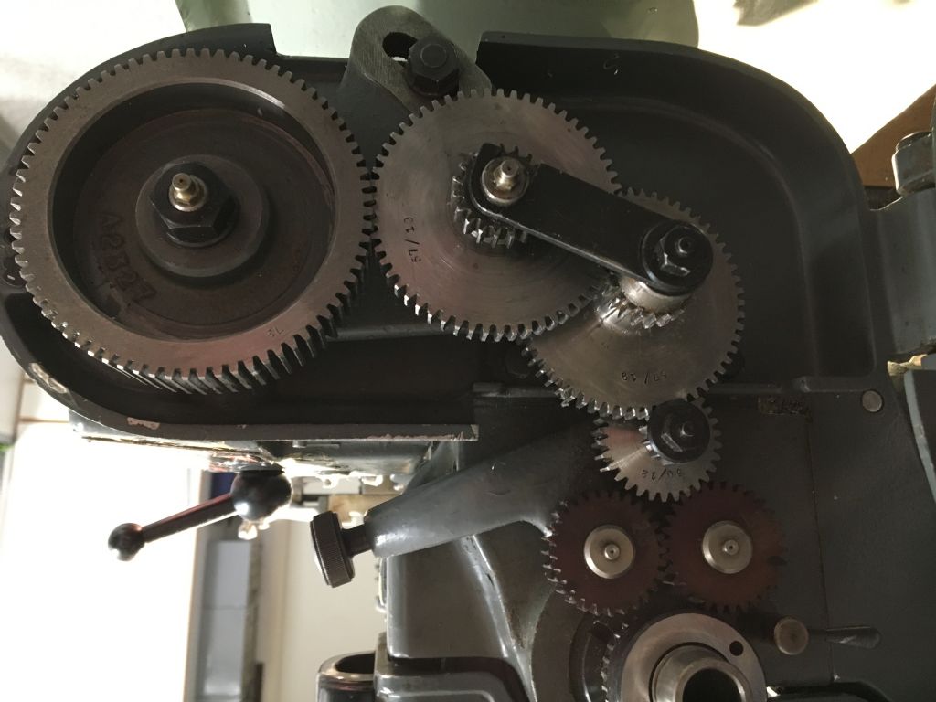
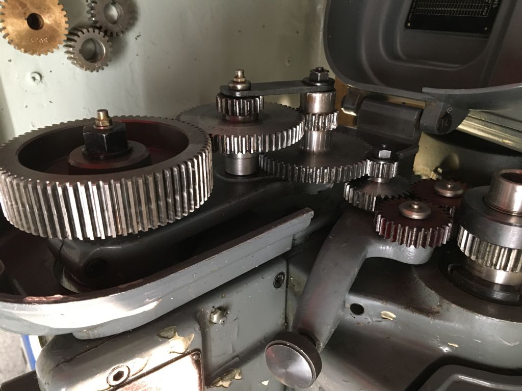
| 6 forum posts 13 photos | Dear members 40 years has gone since my education as a fine mechanical engineer and also 40 years away from machining I just bought a Myford Super 7 anno 1955-56 (2 years older than me) for making various bits and pieces. First job was to make a nut with an internal thread M62x1,25 for my Arboga Milling machine. Made in Stainless steel all turning and slotting went very well but the pitch wasn't accurate The super 7 is delivered i July 1956 to Greenland, Serialno SK 4986 with gearbox serialno QC 1942. I just have the fitted gears From spindle: 30, 30 and 28 fibre, 30T/12T, 57T/19T, 57T/19T, 72T(on the gearbox) Main priority is metric threads but I also need some inch cutting. I'm obviously are missing some gears; have read in here about a 33T and 34T but assume it won't fit my machine - or if - where to fit and where to get them I hope for some useful help - all the best from Jesper in Denmark I didn't figure out how to insert picture
|
| DC31k | 24/11/2019 07:55:14 |
| 1186 forum posts 11 photos | Until someone more qualified comes along, please have a look here: https://www.model-engineer.co.uk/forums/postings.asp?th=125630 as I think it will answer most questions. |
| David George 1 | 24/11/2019 08:26:36 |
 2110 forum posts 565 photos | Hi Jesper welcome to the forum. I don't know about your Myford but on my Drummond I have a list which tells you the change gears on the headstock and you should be able to change the gears to cut metric threads with no problem if you have the gears in the list. They are available to buy either second hand or new. If you search on this site put in screw cutting metric threads in the small box at the top of this page, keyword, it will come up with lots of information and pictures already listed as this question has come up before also i am sure more knowable will post soon. David |
| Simon Williams 3 | 24/11/2019 09:33:51 |
| 728 forum posts 90 photos | Good morning Jesper, hopefully Brian Wood will chip in shortly, can I suggest you need a copy of his book "Gearing of Lathes for Screwcutting" which covers this in detail and answers the questions you are asking. Copies usually available from Arc Euro and also Amazon. Essentially you need the magic gears, but I suspect from the date you have the early version of the quick cutting gearbox, the difference is a 2:1 reduction in the later box which means for you that you need a 17 and a 16-1/2 tooth gear on the mandrel to cut accurate metric threads, not the 34 and 33 tooth gears. If you can work out how to post a picture of the right hand side of the gearbox we can determine which gear box you have, and hence which gears are needed. [Edit: the 30/12 cluster gear in the gear train you have described in your initial post confirms that we're dealing with the older style gearbox.] The 16-1/2 tooth gear sounds mighty odd, but don't worry all will be explained. You might like to do a bit of back ground reading on the subject here: https://www.model-engineer.co.uk/forums/postings.asp?th=125630 QCGB1 should take you there Also: https://www.model-engineer.co.uk/forums/postings.asp?th=131985 QCGB2 links to it. To post a picture you have to upload a JPG to a site album first, then reference it in your post. So , log in, go to Albums on the header and start a new album giving it a suitable name. Now up load your picture in jpg format, it helps if the file size is sensible but I think I've read that the forum software sizes the file anyway if needs be. Now you can write a forum message, and include your picture by using the little camera icon in the message header. This opens a screen where you browse to the picture you want to include in the album you just started, and then pastes it into your message for the rest of us to see. Hope that makes sense. and if I've missed anything out please could those with more knowledge correct my summary. Hope that helps, this is a subject with plenty of reference stuff on the forum, so I'm sure we can sort out the problem you have encountered. Best rgds Simon
Edited By Simon Williams 3 on 24/11/2019 09:42:53 |
| not done it yet | 24/11/2019 09:48:47 |
| 7517 forum posts 20 photos | The 16-1/2 tooth gear sounds mighty odd It does to me, too.
|
| Simon Williams 3 | 24/11/2019 10:19:50 |
| 728 forum posts 90 photos | NDIY - The explanation is in the two threads I have referenced. No, I haven't worked out how to make a half tooth - well not intentionally anyway. The key to this is that the gear cluster is either a 17 : 30 or alternatively 16-1/2 : 30. as a compound pair. You need both sets to achieve the whole range of standard metric pitches for the sort of sizes a Myford owner might encounter. 16-1/2.: 30 is almost exactly 16 : 29, so that's what I made. John Stevenson worked out for me how to make a 29 tooth gear on a 30 T blank so it would mesh correctly with the tumbler gears. Details are in the two threads referenced above. Works a treat, and I'm fairly certain that's what Jesper needs to solve the pitch error problem he has encountered. Rgds Simon |
| Lambton | 24/11/2019 10:24:25 |
 694 forum posts 2 photos | Jesper, The first thing that you should do is get a proper Myford handbook for your model of lathe. Obtainable to buy from Myford **LINK** PDFs of the handbook can be down loaded free from the net. It is difficult to cut metric threads on a gearbox fitted Super 7 without having the correct gears and A2469 quadrant. However no lathe with an imperial lead screw can ever cut true metric threads unless a 127 change wheel is used in the gear train. 33 and 34 tooth gears can be used by fitting either in place of the 24 tooth driver gear from the tumbler reverse output and then selecting the appropriate gear box TPI setting (see chart which includes other gears that provide the most accurate metric threads possible Separate post. Eric
m
|
| Lambton | 24/11/2019 10:37:56 |
694 forum posts 2 photos | Jasper I have sent you a personal message Please look at green INBOX button the top of the page which should be flashing .Eric |
| Brian Wood | 24/11/2019 10:53:38 |
| 2742 forum posts 39 photos | Simon and Jesper, Simon and I had a lot of correspondence on this topic some time ago and the trouble he had applying my book methods to his lathe with the early gearbox. You will recognise one by the small additional housing on the carriage side into which the leadscrew goes. I can't add anything useful to what Simon says so read the story that he has given you links to, it will get you past the difficulties you are having and into the promised land! The results you will get will still be approximations, but they are more than close enough for the sort of work we do. Lambton is quite correct in saying that true values need a final change wheel of 127 teeth in the chain but it is a wheel of very nearly 6.5 inches in diameter. The lathe needs raising blocks to get it clear of the bench, or positioning so that it can run in fresh air over the end of the bench. Never mind the cost of buying it either! Regards Brian |
| Michael Gilligan | 24/11/2019 11:15:47 |
 23121 forum posts 1360 photos | Posted by Brian Wood on 24/11/2019 10:53:38:
[…] Lambton is quite correct in saying that true values need a final change wheel of 127 teeth in the chain but it is a wheel of very nearly 6.5 inches in diameter. The lathe needs raising blocks to get it clear of the bench, or positioning so that it can run in fresh air over the end of the bench. Never mind the cost of buying it either . ... or perhaps you could follow the example of Martin Cleeve, and use a reduced pitch for the conversion gears:
. MichaelG. |
| Simon Williams 3 | 24/11/2019 13:06:23 |
| 728 forum posts 90 photos | MichaelG - thanks for your contribution, that's a very neat solution to the problem. However one of the main advantages to using substitute gears on the mandrel and retaining the other (standard) gears taking the drive to the gearbox input gear is to retain the availability of the fine feed function. Brian and I examined the pitch error introduced by using 17 and 16-1/2 tooth gears, I'm happy the error is insignificant and within the normal working tolerances of the single point screw cutting technique. There is a summary table in one of the threads referenced which lists the theoretical error. There's nothing not to like, apart from the intricacies of making these compound gear sets. HTH Simon Edited By Simon Williams 3 on 24/11/2019 13:07:45 |
| Michael Gilligan | 24/11/2019 13:17:03 |
23121 forum posts 1360 photos | Posted by Simon Williams 3 on 24/11/2019 13:06:23:
MichaelG - thanks for your contribution, that's a very neat solution to the problem. However one of the main advantages to using substitute gears on the mandrel and retaining the other (standard) gears taking the drive to the gearbox input gear is to retain the availability of the fine feed function. […] . Understood and accepted, Simon ... Yours is clearly the right approach for a gearboxed lathe. Cleeve’s was just a regular ML7 [or at least that’s how it started life] MichaelG. |
| Jesper Crone | 24/11/2019 13:58:47 |
| 6 forum posts 13 photos | Posted by Jesper Crone on 23/11/2019 22:33:25:
Dear members 40 years has gone since my education as a fine mechanical engineer and also 40 years away from machining I just bought a Myford Super 7 anno 1955-56 (2 years older than me) for making various bits and pieces. First job was to make a nut with an internal thread M62x1,25 for my Arboga Milling machine. Made in Stainless steel all turning and slotting went very well but the pitch wasn't accurate The super 7 is delivered i July 1956 to Greenland, Serialno SK 4986 with gearbox serialno QC 1942. I just have the fitted gears From spindle: 30T, 30T and 28T fibre, 30T/12T, 57T/19T, 57T/19T, 72T(on the gearbox) Main priority is metric threads but I also need some inch cutting. I'm obviously are missing some gears; have read in here about a 33T and 34T but assume it won't fit my machine - or if - where to fit and where to get them I hope for some useful help - all the best from Jesper in Denmark I didn't figure out how to insert picture
|
| Simon Williams 3 | 24/11/2019 14:18:55 |
| 728 forum posts 90 photos |
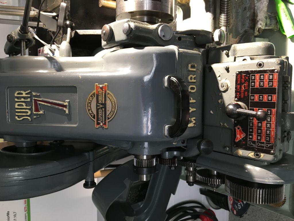
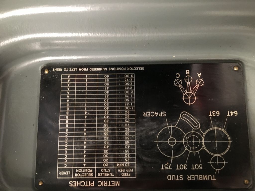
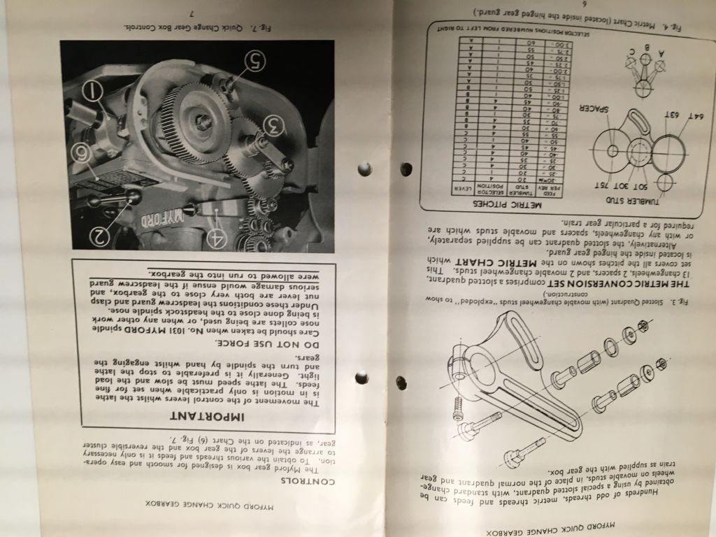
Ah ha! Hello again Jesper, and thanks for the pictures. You obviously sussed out how to load them! But...…. The plot thickens! Because the label you show from the inside of the gear cover isn't the right one! That label belongs with the standard Myford metric banjo kit, which was marketed to go with the NEWER gearbox, not the one you and I have got. The 2:1 gear reduction factor has to be taken into account. So here is a picture of the label inside the cover of the gearbox I have.
If you have followed the links I showed earlier you will have realised that this is irrelevant, as using the 17 or 16-1/2 compound input gears sidesteps this problem. HTH Simon
|
| Roderick Jenkins | 24/11/2019 16:27:14 |
 2376 forum posts 800 photos | My best guess is that the gearbox is a later addition to the lathe, it certainly looks similar to the gearbox on my S7. If this is the case then the 33/34 T system will work.. The gears are available from RGD **LINK** This table shows the actual pitch of threads that can be made with this arrangement:
Rod |
| Brian Wood | 24/11/2019 17:54:10 |
| 2742 forum posts 39 photos | Hello Roderick, Jesper and Simon both have the early gearbox. It has a small outrigger housing on the carriage side of the gearbox with a pair of 18 T gears insideto make the leadscrew turn in a logical direction. I don't think your gearbox is of this pattern and therefore your table is valid for the later gearboxes Simon and John Stevenson worked out the fiddle gearing needed to get the early gearboxes to work, but as we have seen, the table installed in Jesper's lathe is not matched to the gearbox that is fitted to his lathe; in which case your table will not help him either I'm afraid. This is yet another combination of conditions brought about by incorrect matching of parts, possibly brought about by fitting the early gearbox to a bare lathe without appreciating the subtleties involved. . If Jesper could test his lathe using Simon's table, that should work. Whether he has the gears to do it I don't know Regards Brian |
| Jesper Crone | 24/11/2019 20:49:28 |
| 6 forum posts 13 photos |
Posted by Jesper Crone on 24/11/2019 13:58:47: Posted by Jesper Crone on 23/11/2019 22:33:25:
Dear members 40 years has gone since my education as a fine mechanical engineer and also 40 years away from machining I just bought a Myford Super 7 anno 1955-56 (2 years older than me) for making various bits and pieces. First job was to make a nut with an internal thread M62x1,25 for my Arboga Milling machine. Made in Stainless steel all turning and slotting went very well but the pitch wasn't accurate The super 7 is delivered i July 1956 to Greenland, Serialno SK 4986 with gearbox serialno QC 1942. I just have the fitted gears From spindle: 30T, 30T and 28T fibre, 30T/12T, 57T/19T, 57T/19T, 72T(on the gearbox) Main priority is metric threads but I also need some inch cutting. I'm obviously are missing some gears; have read in here about a 33T and 34T but assume it won't fit my machine - or if - where to fit and where to get them I hope for some useful help - all the best from Jesper in Denmark I didn't figure out how to insert picture
Thank you very much for all your kind posts; I will get hold on the bible about gearing for screwcutting. I'm pretty sure that the gearbox was delivered with the machine in 1956 as I have both manuals; Lathe publ S.715 dated 56 and gearbox publ 712 dated 56 with the gearing chart as per pictures. BUT I have no extra gears than fitted on the pictures - so I'm much in doubt what I need to buy in order to cut metric screws - and I do not understand the 161/2 teeth gear nor where to buy.
|
| Roderick Jenkins | 24/11/2019 22:43:24 |
2376 forum posts 800 photos | Hmm. Jesper's pictures seems to show a manual for the later type of gearbox as well as having the later plate in the cover. The 1680 gearbox is the same as retro-fitted to my S7. How can we determine which gearbox Jesper actually has? Rod Edit. I've just had a look at Tony's Lathes site and I see that 1956 was the year of change to the newer style gear box. Could Jesper's be some form of transitional box , old externals but new internals? Edited By Roderick Jenkins on 24/11/2019 23:25:16 |
| peak4 | 25/11/2019 00:08:17 |
 2207 forum posts 210 photos | Posted by Roderick Jenkins on 24/11/2019 22:43:24:
Hmm. Jesper's pictures seems to show a manual for the later type of gearbox as well as having the later plate in the cover. The 1680 gearbox is the same as retro-fitted to my S7. How can we determine which gearbox Jesper actually has? Rod Edit. I've just had a look at Tony's Lathes site and I see that 1956 was the year of change to the newer style gear box. Could Jesper's be some form of transitional box , old externals but new internals? Edited By Roderick Jenkins on 24/11/2019 23:25:16 Tony's site suggests that; Since we know that Jesper's box has a serial no of QC1942, and photos also show the earlier version, with the little external gear cover on the right hand side, probably give the game away. p.s. May I also recommend Faststone Image Viewer as a good program for basic image manipulation, including correcting orientation. Edited By peak4 on 25/11/2019 00:13:15 |
| Simon Williams 3 | 25/11/2019 19:33:19 |
| 728 forum posts 90 photos | Jesper - good evening. Firstly my apologies for not picking up your questions sooner, I've been out of touch for a day. So, if I may I would like to summarise what we think we know, and answer your question about obtaining the requisite gear. I believe we have established that you have the older type QCGB, that's what the photo's of the lathe indicate, and the fact that you have a 30/12 cluster gear in the gear train on the mandrel gear suggests the same. What we don't know for absolutely certain is whether the lathe cuts the threads as indicated on the gearbox label. It's just possible that there is a mismatch here, and the gearbox cuts either twice or half the threads per inch that is indicated. This of course is when you are cutting an imperial thread such as 20TPI. The label inside the gear cover sows a seed of doubt in my mind, and I would just like to be sure we know where we are starting from before telling you what to do next. Can you try cutting a thread with the gearbox set up for (say) 20TPI - it needs only be a scratch pass to prove the gear train - and confirm that it is 20 TPI that you get. I chose 20 TPI because it is the same thing as 1.27 mm pitch - and if the M62 nut you were trying to make is only fairly short you may find that using a 20 TPI thread instead of 1.25 mm pitch gives acceptable results. After all the error is only 0,02 mm per revolution - so if your nut is 10 mm thick the thread error is still only +/- 0.08 mm. However, we can do better. ASSUMING the gearbox IS the old one, the gear train you have identified starts with a 30 tooth gear with a 12 tooth gear married to it to make a compound gear. This gives the thread per inch selection as per the label on top of the gearbox. If we change the 12 tooth gear for say 18 teeth we'll get a different set of TPI values for each position of the gearbox selector levers. In this example the gearbox output is speeded up by 50%, so our 20 TPI setting will now cut 13.3 (Edit - I got this wrong in my initial post - it's less TPI because the lead screw is running faster. OOPS!) TPI. Using other input gears gives us control over the threads on the workpiece over and above the "normal" (standard settings. One such choice is a 17 tooth gear. If we change the 12 tooth gear to be 17 teeth, and set the gearbox levers in the positions for 24TPI we get 16.94TPI, which equates to 1.499 mm pitch. The arithmetic is simple pro-rata gear ratios, but work it out in TPI and then convert to mm pitch last. So that's a nice accurate answer for 1.5 mm pitch. also 3mm, and 0.75 which is an oddity but it shows the principle. How do we go about getting 1.25 mm pitch. Do the same arithmetic, and you find you need a 16-1/2 tooth gear. Now whatever I've said before, I haven't worked out a way of making a single non whole number gear. But it isn't a single gear we're working with , it's a compound pair. The other gear of the compound pair was always 30 teeth, giving a 1 : 1 ratio with the chuck, but it doesn't have to be. 16-1/2 : 30 is very close to 16 : 29, so if we change the input gear to be 29 teeth meshing with the tumbler gear, and now 16 teeth driving the otherwise standard gear train going down to the gearbox input we get jolly close to 1.25 pitch. And 2.5, also 0.625, another size we're likely never going to want! Enough for a moment, this post is long enough already, I'll continue in a second instalment.
Edited By Simon Williams 3 on 25/11/2019 19:37:41 |


Please login to post a reply.
Magazine Locator
Want the latest issue of Model Engineer or Model Engineers' Workshop? Use our magazine locator links to find your nearest stockist!
Sign up to our Newsletter
Sign up to our newsletter and get a free digital issue.
You can unsubscribe at anytime. View our privacy policy at www.mortons.co.uk/privacy
Latest Forum Posts
- hemingway ball turner
04/07/2025 14:40:26 - *Oct 2023: FORUM MIGRATION TIMELINE*
05/10/2023 07:57:11 - Making ER11 collet chuck
05/10/2023 07:56:24 - What did you do today? 2023
05/10/2023 07:25:01 - Orrery
05/10/2023 06:00:41 - Wera hand-tools
05/10/2023 05:47:07 - New member
05/10/2023 04:40:11 - Problems with external pot on at1 vfd
05/10/2023 00:06:32 - Drain plug
04/10/2023 23:36:17 - digi phase converter for 10 machines.....
04/10/2023 23:13:48 - More Latest Posts...
- View All Topics
Support Our Partners


Shopping Partners
Subscription Offer

Latest "For Sale" Ads
- Reeves** - Rebuilt Royal Scot by Martin Evans
by John Broughton
£300.00 - BRITANNIA 5" GAUGE James Perrier
by Jon Seabright 1
£2,500.00 - Drill Grinder - for restoration
by Nigel Graham 2
£0.00 - WARCO WM18 MILLING MACHINE
by Alex Chudley
£1,200.00 - MYFORD SUPER 7 LATHE
by Alex Chudley
£2,000.00 - More "For Sale" Ads...
Latest "Wanted" Ads
- D1-3 backplate
by Michael Horley
Price Not Specified - fixed steady for a Colchester bantam mark1 800
by George Jervis
Price Not Specified - lbsc pansy
by JACK SIDEBOTHAM
Price Not Specified - Pratt Burnerd multifit chuck key.
by Tim Riome
Price Not Specified - BANDSAW BLADE WELDER
by HUGH
Price Not Specified - More "Wanted" Ads...
Get In Touch!
Do you want to contact the Model Engineer and Model Engineers' Workshop team?
You can contact us by phone, mail or email about the magazines including becoming a contributor, submitting reader's letters or making queries about articles. You can also get in touch about this website, advertising or other general issues.
Click THIS LINK for full contact details.
For subscription issues please see THIS LINK.
Digital Back Issues


Donate

 Register
 Log-in
Model Engineer Magazine
- Percival Marshall
- M.E. History
- LittleLEC
- M.E. Clock

ME Workshop
- An Adcock
- & Shipley
- Horizontal
- Mill

Subscribe Now
- Great savings
- Delivered to your door

Pre-order your copy!
- Delivered to your doorstep!
- Free UK delivery!
All Forum Topics > Manual machine tools > Myford Super 7 Metric thread cutting gears