Forum sponsored by:

Centaur engine timing gears
| AJW | 02/09/2018 00:07:41 |
 388 forum posts 137 photos | I am planning to build the above engine from castings supplied by Reeves. Unfortunately they don't list the correct timing gears, they can supply 'similar gears' which would involve repositioning the camshaft to account for the gears increased centre's dimension. Before I interrogate the web for something more suitable,is the Reeves offering the closest I am going to get? Alan |
| JasonB | 02/09/2018 07:39:58 |
 25215 forum posts 3105 photos 1 articles | Mention of using stock gears from HPC here |
| AJW | 02/09/2018 19:10:15 |
388 forum posts 137 photos | Thanks for that, what a great supplier! (HPC Gears) Looks like stock gears can be used with little modification, however I am now spoilt for choice - they can supply left and right hand helical! Next question - would I need to order left or right hand helical? Alan |
| John Rudd | 02/09/2018 20:28:22 |
| 1479 forum posts 1 photos | Posted by AJW on 02/09/2018 19:10:15:
Thanks for that, what a great supplier! (HPC Gears) Next question - would I need to order left or right hand helical? Alan What do the plans call for? (I dont think it makes a difference, but you never know! ) Edited By John Rudd on 02/09/2018 20:29:01 |
| JasonB | 02/09/2018 20:33:29 |
25215 forum posts 3105 photos 1 articles | I think they are right hand, could not see it mentioned in the ME articles Left or right would alter the direction of the camshaft so you would need to bear that in mind when timing the engine |
| Andrew Johnston | 02/09/2018 20:37:11 |
 7061 forum posts 719 photos | Looking at a picture of the engine they appear to be RH. Ideally they would be arranged such that the axial forces on the gear are resisted by the larger bearing surface, whichever one it may be. Andrew |
| AJW | 02/09/2018 22:51:34 |
388 forum posts 137 photos | Yes I think your correct - rh, looking at the drawing the gears are described as skew gears but do appear to have teeth sketched on them and are rh. Thanks all. Alan |
| bricky | 03/09/2018 16:13:50 |
| 627 forum posts 72 photos | I built the Centaur and when I came to fitting the skew gears I found that the gears supplied by Reeves were to big to fit on the cam shaft.I had to mill a cavity in the side to allow the gear to mesh properly,this cavity was nearly through.When selling castings and parts for the engine the supplier should ensure that they are correct,this was not a mistake, they told me if I wanted gears to fit I would have to look for another supplier.It,s a nice engine to build . Frank
|
| AJW | 03/09/2018 17:14:22 |
388 forum posts 137 photos | Thanks for the heads up. I think it's a bit poor show to supply gearing that is not 'quite' suitable. I have ordered a pair of gears from HPC Gears, who have a fantastic range. I will be ordering castings from Reeves and I will suggest that they use HPC as a supplier as the gears are far closer to the original spec. Looks to be a lovely engine, looking forward to getting started! Alan Edited By AJW on 03/09/2018 17:15:40 |
| Roderick Jenkins | 03/09/2018 18:17:24 |
 2376 forum posts 800 photos | I'm not sure that the criticism of Reeves is justified. ETW specified skew (helical) gears that had differing helix angles ( approx 60 and 30 degrees) such that they were the same diameter. This allowed the gears to fit nicely in the space he designed (probably ! ) The only readily available helical gears are 45 degrees so a compromise has to be reached. If you have found 45 degree gears that fit then it is possible that the gears will be too small for the load they have to carry (but I doubt it). Basically, Reeves have offered one solution (perhaps the same DP as the original gears but both 45 degree helix angle rather than a 30/60 pair). You have chosen a different solution - neither is correct according to the original design. Cheers, Rod |
| AJW | 03/09/2018 22:29:36 |
388 forum posts 137 photos | I realise that ETW was using gears with different skew angles which he suggested were salvaged from motor car distributor or speedometer drives but I think the chance of finding these now is long gone! I would imagine it is nigh on impossible to find off the shelf gearing of the original specifications. Alan |
| Roderick Jenkins | 03/09/2018 23:35:38 |
2376 forum posts 800 photos | Alan, As you know, ETW was, in fact, very vague about the size of the gears and we can't be sure that he got it right. I made the "correct" skew gears for my Wyvern and still had to relieve the bracket to give clearance for the driven gear to rotate. I still revere the man though and I'm sure you will end up with a splendid engine. Enjoy the journey, Rod |
| Phil P | 03/09/2018 23:56:16 |
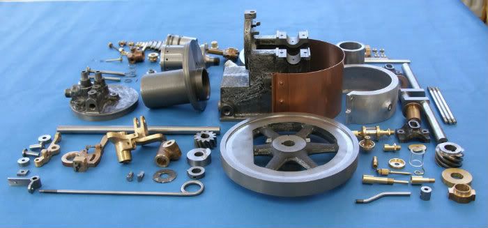
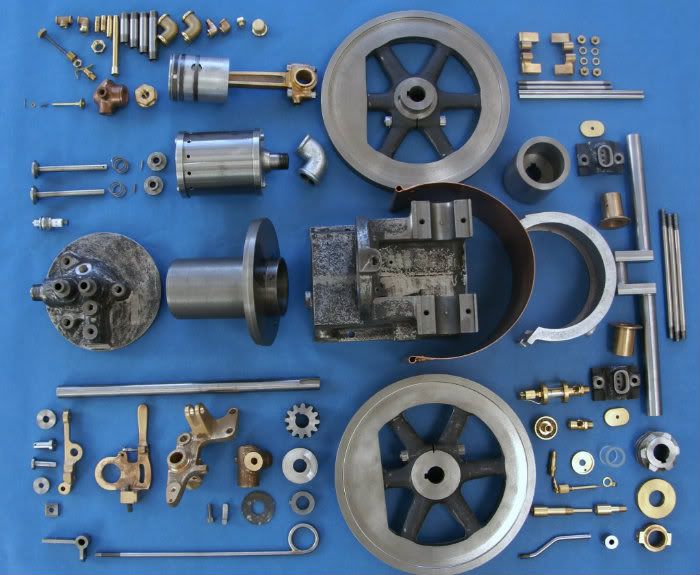
| 851 forum posts 206 photos | What you need is a pair of gears like the ones in front of these castings.
My dad made those many years ago on his CVA hobbing machine. Phil |
| JasonB | 04/09/2018 07:13:15 |
25215 forum posts 3105 photos 1 articles | I suppose for those without the equipment to cut them you could draw them up in cad and send off the files to be printed in one of the sintered metals or LWC. They ar enot taking a massive load or going really fast. Or make up the jig that Chuck Fellows came up with to allow you to cut them on your home mill. If you did make them yourself you could probably get the drive gear bigger than the driven with the right helix angles and this may actually be what is shown on the cover illustration. I just had a look back at the photos of teh 1/2 scale Domestic that I made and the 6T crankshaft gear is a larger than the 12T driven camshaft gear
Edited By JasonB on 04/09/2018 07:51:32 |
| Michael Gilligan | 04/09/2018 07:50:11 |
 23121 forum posts 1360 photos | Posted by JasonB on 04/09/2018 07:13:15:
... Or make up the jig that Chuck Fellows came up with to allow you to cut them on your home mill. . I followed that hint, Jason, and also found this : **LINK** https://m.youtube.com/watch?v=oSeMX9SZXXY Very impressive ... Thanks MichaelG.
|
| JasonB | 04/09/2018 07:53:59 |
25215 forum posts 3105 photos 1 articles | There is also this video of the same set up by George Britnell https://youtu.be/blaZ5tz0_6E Drawings and a couple of threads about it can be found on MEM forum, may need to be a member to get at the drawings. Edited By JasonB on 04/09/2018 07:55:44 |
| Michael Gilligan | 04/09/2018 08:30:27 |
23121 forum posts 1360 photos | Posted by JasonB on 04/09/2018 07:53:59:
There is also this video of the same set up by George Britnell https://youtu.be/blaZ5tz0_6E Drawings and a couple of threads about it can be found on MEM forum, may need to be a member to get at the drawings. . Thanks for the extra video link, Jason ... do you think they would let me in ? |
| Maurice | 04/09/2018 11:38:55 |
| 469 forum posts 50 photos | For suitable gears for your gas engine, you might look out for unwanted sewing machines. Not too old. My daughter discarded one. Naturally I had it to bits to see if there was anything useful inside. Not really, except for a pair of 2:1 helical gears! One is brass and one steel. They are both a fraction over 3/4” diameter, and 3/4” working centres. The steel one is 13/16”. long with a half inch bore that fits my crankshaft perfectly. The brass one is 3/8” long, and 15/32” bore. I have not yet compared them to the drawings, as this is a “back burner” project that I inherited from an old friend; but they look a better bet than the ones that came with the castings. |
| AJW | 04/09/2018 13:11:22 |
388 forum posts 137 photos | Great! Worth a look. I always strip down discarded stuff for anything that might be useful but I reckon my wife might notice the sewing machine not working! Alan |
| AJW | 04/09/2018 15:04:31 |
388 forum posts 137 photos | The HPC gears turned up today, very quick delivery. Nicely made pair of gears in steel which give a centre to centre working dimension of 0.795 which is not a million miles away from the original drawing dimension of 0.875. This should result in a minimal amount of camshaft repositioning. Alan |

Please login to post a reply.
Magazine Locator
Want the latest issue of Model Engineer or Model Engineers' Workshop? Use our magazine locator links to find your nearest stockist!
Sign up to our Newsletter
Sign up to our newsletter and get a free digital issue.
You can unsubscribe at anytime. View our privacy policy at www.mortons.co.uk/privacy
Latest Forum Posts
- *Oct 2023: FORUM MIGRATION TIMELINE*
05/10/2023 07:57:11 - Making ER11 collet chuck
05/10/2023 07:56:24 - What did you do today? 2023
05/10/2023 07:25:01 - Orrery
05/10/2023 06:00:41 - Wera hand-tools
05/10/2023 05:47:07 - New member
05/10/2023 04:40:11 - Problems with external pot on at1 vfd
05/10/2023 00:06:32 - Drain plug
04/10/2023 23:36:17 - digi phase converter for 10 machines.....
04/10/2023 23:13:48 - Winter Storage Of Locomotives
04/10/2023 21:02:11 - More Latest Posts...
- View All Topics
Support Our Partners


Shopping Partners
Subscription Offer

Latest "For Sale" Ads
- Reeves** - Rebuilt Royal Scot by Martin Evans
by John Broughton
£300.00 - BRITANNIA 5" GAUGE James Perrier
by Jon Seabright 1
£2,500.00 - Drill Grinder - for restoration
by Nigel Graham 2
£0.00 - WARCO WM18 MILLING MACHINE
by Alex Chudley
£1,200.00 - MYFORD SUPER 7 LATHE
by Alex Chudley
£2,000.00 - More "For Sale" Ads...
Latest "Wanted" Ads
- D1-3 backplate
by Michael Horley
Price Not Specified - fixed steady for a Colchester bantam mark1 800
by George Jervis
Price Not Specified - lbsc pansy
by JACK SIDEBOTHAM
Price Not Specified - Pratt Burnerd multifit chuck key.
by Tim Riome
Price Not Specified - BANDSAW BLADE WELDER
by HUGH
Price Not Specified - More "Wanted" Ads...
Get In Touch!
Do you want to contact the Model Engineer and Model Engineers' Workshop team?
You can contact us by phone, mail or email about the magazines including becoming a contributor, submitting reader's letters or making queries about articles. You can also get in touch about this website, advertising or other general issues.
Click THIS LINK for full contact details.
For subscription issues please see THIS LINK.
Digital Back Issues


Donate

 Register
 Log-in
Model Engineer Magazine
- Percival Marshall
- M.E. History
- LittleLEC
- M.E. Clock

ME Workshop
- An Adcock
- & Shipley
- Horizontal
- Mill

Subscribe Now
- Great savings
- Delivered to your door

Pre-order your copy!
- Delivered to your doorstep!
- Free UK delivery!
All Forum Topics > I/C Engines > Centaur engine timing gears