Forum sponsored by:

Looking for lathe mandrel test bars.
| Andrew Tinsley | 12/07/2018 20:37:01 |
| 1817 forum posts 2 photos | I would like to buy a 2MT and 3 MT lathe mandrel test bar. Or a combined bar for those 2 sizes. All I seem able to find are those made by ATOZ of India. Now their specification sheets look good, But I have yet to find much good stuff made in India, apart from the excellent Zither chucks, Does anyone have either of these test bars made by Atoz and are they as good as the spec sheet claim? I appreciate that their are other methods of alignment (Rolley's Dad's method etc), but I would prefer a direct measuring system if possible. Regards, Andrew. |
| Ian Skeldon 2 | 12/07/2018 21:07:59 |
| 543 forum posts 54 photos | You could try these **LINK**
|
| Andrew Tinsley | 12/07/2018 21:13:16 |
| 1817 forum posts 2 photos | Thanks Ian, I have been told that the RDG test bars are in fact made by ATOZ. Although I don't know if this is true or not. Andrew. |
| Gordon Tarling | 14/07/2018 09:21:44 |
| 185 forum posts 4 photos | I bought one from Arc Euro, though I have no idea of who the manufacturer is. |
| Andrew Tinsley | 14/07/2018 10:14:58 |
| 1817 forum posts 2 photos | Hello Gordon, That is interesting as I could not find one when I looked at Arc. It was my first port of call as usual. Thanks, Andrew. |
| Brian Wood | 14/07/2018 11:25:17 |
| 2742 forum posts 39 photos | Hello Andrew, Warco sell them too, but not double ended; that would be a special made to order I feel sure Regards Brian |
| Andrew Tinsley | 14/07/2018 11:46:39 |
| 1817 forum posts 2 photos | Hello Brian, Atoz make a double ended 2mt / 3mt bar. The specification is very comprehensive and looks good. Trouble is I am very suspicious of Indian made kit, having been stung before now with equally good speecifications that turned out to be wrong! Andrew. |
| Ketan Swali | 14/07/2018 12:17:27 |
| 1481 forum posts 149 photos | Hi Andrew, This is an interesting product. Unfortunately, it falls into the 'mine is bigger than yours' bracket. We were selling it, and we had great sales for it. However, there is and will remain a question over its use. The original method of its use was/is to load it into the MT female hole of the headstock, and keep the parallel part free running WITHOUT being supported by any centre in the tailstock. The key idea being to measure the alignment and run-out of the spindle in the headstock (in simple terms). Then comes the question of: how far away from the head such measurements should be taken. The general answer being between 100mm to 150mm max.average - away from the headstock, depending on the type of lathe/headstock assembly. However, various issues came to light:
If the real purpose was the first - i.e. checking of the headstock, results were uncertain, and there needed to be some point of reference which was difficult to ascertain. Although we were happy with the bars we sold in most cases, in the hobby environment, the conclusion was that no test bars currently on the market over short nominal lengths were quite correct - keeping in mind the original principal. However, they were fine depending on intended purpose of use - such as between centres. Although we have removed the bars from sale a while back, based on principal, the maker is happy selling them successfully to customers in U.S., Germany, Israel and Australia, in good volume, without a single question being raised over accuracy. ATOZ is a trading company. They do not buy from our maker, as they are unable to pay our maker the price for the quality they make. Andrew, I am sending you a PM shortly. Ketan at ARC. |
| Ketan Swali | 14/07/2018 12:50:54 |
| 1481 forum posts 149 photos | Just to clarify 'between centres': The bars we sold had a drawbar thread at the end of the morse taper. However, many such bars come with a 'centre drill point' (for want of word), at that end instead of a drawbar thread. This allows a centre to locate into the bar at the headstock, with a similar point for a centre to locate at the tailstock end. i.e. between centres. For all of this to be 'true' the 'centre drilling' at both ends needs to be accurate at time of making such bars. As the bars which ARC used to sell had a drawbar end, one had to locate the male morse into the female hole of the headstock, and support at the tail end with a centre, which still worked for the purpose of 'between centres'. Ketan at ARC. |
| Michael Gilligan | 14/07/2018 13:21:30 |
 23121 forum posts 1360 photos | Further to Ketan's helpful note: It is worth mentioning that Schlesinger paid particular attention to the design of test bars ... His were taper mounted, but unsupported at the distal end; and they were bored-out in steps [to approximate a taper] so as to reduce the tendency to 'sag under their own weight'. MichaelG. . Sorry, the document is, apparently, still protected by copyright so I don't feel at liberty to share a link.
|
| mechman48 | 14/07/2018 16:13:40 |
 2947 forum posts 468 photos | Have a look at ... seemingly they have just come into stock... |
| John Reese | 15/07/2018 02:06:20 |
 1071 forum posts | I never thought test bars were useful except for checking runout of the spindle taper. To check headstock alignment with the ways just chuck up a piece of bar and take a light cut off the OD. The diameter should be the same at both ends. If not, the headstock is misaligned with the ways, To check tailstock alignment first make up a bar with centers in both ends. Machine away most of the OD to leave an unmachined collar at each end. The collar nearest the headstock needs to be long enough to acommodate a lathe dog. Mount the bar between centers, driving it with a dog. Take a light cut off the collar nearest the tailstock. Advance the carriage to the headstock end of the test bar. Without disturbing the cross slide take a light cut off the collar. If the diameters of the collars are equal the tailstock is in line with the centerline of the spindle (at least it i in the horizontal plane). |
| John McNamara | 15/07/2018 02:42:30 |
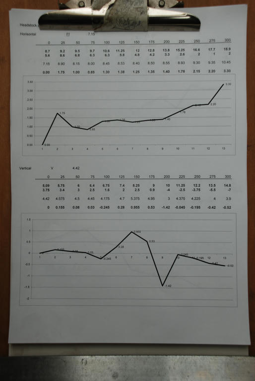
 1377 forum posts 133 photos | Hi All 25 – 40mm is ideal, of constant diameter say to Just set the bar up in your chuck a 3 will do but After cantering one point unless you are very lucky We are going to take several measurements along After setting up your dial indicator on the saddle and You will also need a ruler or other means to move Rule off rule off a piece of paper it will need 4 Now we are ready to find if there is any alignment Before starting check again that the tip of your Then rotate the spindle until the indicator reads Repeat this for all the other positions. At this point you have all the other highs and lows, Alternatively the result will describe a curve this If you can use Excel you can do all this on a This method does not check the alignment of the This method is a very good indicator of the To speed this process up fewer measuring points Regards |
| Martin Connelly | 15/07/2018 10:37:40 |
 2549 forum posts 235 photos | Sag and manufacturing tolerances are the reason industry moved away from mechanical alignment to optical or laser alignment. I have considered the best way to do this in a hobby environment and think a rifle scope looking down the spindle bore at a target mounted on the tailstock would be a good starting point. I don't know how short a distance they can focus down to. Martin C |
| Michael Gilligan | 15/07/2018 10:57:58 |
23121 forum posts 1360 photos | Martin, I doubt if a rifle scope would have the necessary resolution for lathe alignment. An autocollimator is more appropriate: Very expensive as a commercial purchase; but there was an interesting DIY design featured in [two issues, I think] of MEW. MichaelG. |
| Andrew Tinsley | 15/07/2018 11:20:08 |
| 1817 forum posts 2 photos | Thanks everyone, There are some very interesting facts that have come out of this thread. Ketan , as usual, has made some very cogent points, some of which I was unaware of. It is always interesting to hear what an insider in the trade has to say! John, the description of your alignment method sounds like Rolley's dad's (Sp?) method. Like a test bar, this doesn't really tell you what happens when actually cutting metal, but using a test bar (with appropriate care), is a much simpler operation. Whatever method one uses, the real test is how parallel can you turn in practice? Some 40 years ago, I used a test bar to align a headstock and it worked a treat. I never gave a thought to the problems that could arise. I now realise that I was very lucky in getting a good result. I simply ran a DTI down the bar and adjusted the head stock for zero run out! I didn't even check the bar run out by rotating it. There must have been someone looking out for simple minded folk. John, I am not sure that simply turning a bar and checking for the same diameter at both ends is a wise move, unless you know that the bed isn't twisted. I must have checked maybe half a dozen amateur's lathes over the years. Only one was set up with no twist and that belonged to a toolmaker friend of mine who knew what he was about. Maybe someone with more experience than me can chime in here. I think that a combination of a twisted bed and a headstock adjusted to give the same diameter at each end will not necessarily give the same diameter in the centre? I freely admit I could be wrong here! Thanks everyone for some really good comments, Andrew. |
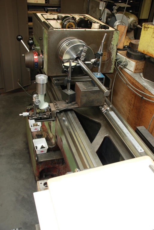
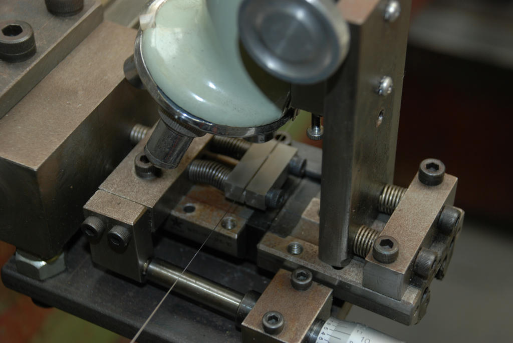
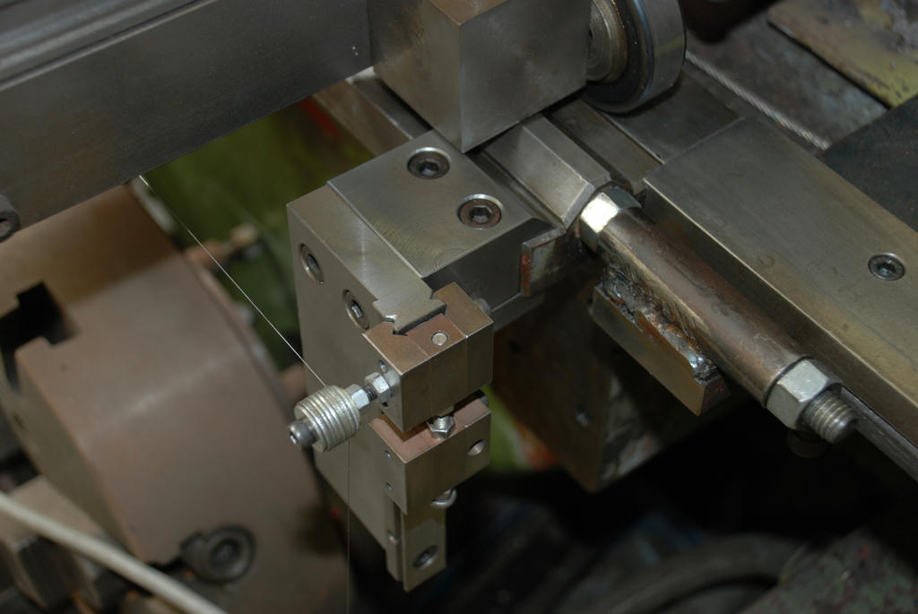
| John McNamara | 16/07/2018 10:38:13 |
1377 forum posts 133 photos | Hi Andrew Hi All Lathe Accuracy measurement. I restored my lathe about 2011, At the time I was thinking on how to align the spindle and came up with the method I mentioned previously. As you can see below I used two dial indicators and a 25mm ground steel bar to check the spindle axis of my lathe. I had had not studied Rollie's method as I thought it related to twisted beds, a case of GMTA. If I had seen this paper recently written I would have tried it instead of the microcope The CERN Accelerator is to this day mainly aligned by wire. Images: Also a couple of images of a wire mounting point, there were 2, one at each end of the bed and the microscope stage kludged up from scrap and a 50 power student microscope, nothing hardened! just scrap It worked well. I don't have measurements it was done on the fly the v groves were just milled. It was however rock solid and sturdy. once adjusted the whole jig was clamped tight that is important. Oh and a tenth accuracy Mitutoyo microscope head and a linear bearing formed the measuring stage that had to position the grove on center before a measurement was taken. The lathe bed was subsequently ground in situ, It worked well and I use the lathe to to this day, is it perfect? no, but almost. I do have a write up but too many pages to post here. Regards
|
Please login to post a reply.
Magazine Locator
Want the latest issue of Model Engineer or Model Engineers' Workshop? Use our magazine locator links to find your nearest stockist!
Sign up to our Newsletter
Sign up to our newsletter and get a free digital issue.
You can unsubscribe at anytime. View our privacy policy at www.mortons.co.uk/privacy
Latest Forum Posts
- *Oct 2023: FORUM MIGRATION TIMELINE*
05/10/2023 07:57:11 - Making ER11 collet chuck
05/10/2023 07:56:24 - What did you do today? 2023
05/10/2023 07:25:01 - Orrery
05/10/2023 06:00:41 - Wera hand-tools
05/10/2023 05:47:07 - New member
05/10/2023 04:40:11 - Problems with external pot on at1 vfd
05/10/2023 00:06:32 - Drain plug
04/10/2023 23:36:17 - digi phase converter for 10 machines.....
04/10/2023 23:13:48 - Winter Storage Of Locomotives
04/10/2023 21:02:11 - More Latest Posts...
- View All Topics
Support Our Partners


Shopping Partners
Subscription Offer

Latest "For Sale" Ads
- Reeves** - Rebuilt Royal Scot by Martin Evans
by John Broughton
£300.00 - BRITANNIA 5" GAUGE James Perrier
by Jon Seabright 1
£2,500.00 - Drill Grinder - for restoration
by Nigel Graham 2
£0.00 - WARCO WM18 MILLING MACHINE
by Alex Chudley
£1,200.00 - MYFORD SUPER 7 LATHE
by Alex Chudley
£2,000.00 - More "For Sale" Ads...
Latest "Wanted" Ads
- D1-3 backplate
by Michael Horley
Price Not Specified - fixed steady for a Colchester bantam mark1 800
by George Jervis
Price Not Specified - lbsc pansy
by JACK SIDEBOTHAM
Price Not Specified - Pratt Burnerd multifit chuck key.
by Tim Riome
Price Not Specified - BANDSAW BLADE WELDER
by HUGH
Price Not Specified - More "Wanted" Ads...
Get In Touch!
Do you want to contact the Model Engineer and Model Engineers' Workshop team?
You can contact us by phone, mail or email about the magazines including becoming a contributor, submitting reader's letters or making queries about articles. You can also get in touch about this website, advertising or other general issues.
Click THIS LINK for full contact details.
For subscription issues please see THIS LINK.
Digital Back Issues


Donate

 Register
 Log-in
Model Engineer Magazine
- Percival Marshall
- M.E. History
- LittleLEC
- M.E. Clock

ME Workshop
- An Adcock
- & Shipley
- Horizontal
- Mill

Subscribe Now
- Great savings
- Delivered to your door

Pre-order your copy!
- Delivered to your doorstep!
- Free UK delivery!
All Forum Topics > General Questions > Looking for lathe mandrel test bars.