Forum sponsored by:

Centre help!!!
Workpiece spinning off centre!
| Christine Walker | 05/12/2016 20:52:57 |
| 37 forum posts | Hello lovely forum friends, I need your help again, please! Arrrgh! OK, I am trying to cut a groove into the outside perimeter of a circular piece (end on so to speak). My other thread explained it with a diagram. So the problem I am having, is that the workpiece isn't centring properly. In a nutshell, I have a 190mm diameter workpiece, mounted on a 180mm diameter piece of ply which is bolted to my faceplate. Somewhere along the line, something isn't centred properly, because the tool touches the perimeter in some places and is up to 2mm away in other places around the circumference. As far as I can tell, I thought I had drilled everything in the centre. I drew the correct size circles in Illustrator and put a centre hole in. These were printed and transferred to the work piece, and used as templates. Everything fitted perfectly. Then, when mounted on the lathe spindle, it is, as explained above, spinning off centre. And I don't know what to do to get it right. It is driving me mad! Any of you chaps any ideas of how to get the workpiece spinning in a perfect motion? Thank you in advance. Christine
|
| JasonB | 05/12/2016 20:58:23 |
 25215 forum posts 3105 photos 1 articles | Loosen the bolts that are holding the ply a little and then tap the ply/work to adjust its position until it runs true then tighten up. Ideally an oversize bit of ply should be mounted on teh faceplate and then turned down until your plastic tube fits snugly. (assuming it has an even wall thickness.
J |
| Michael Gilligan | 05/12/2016 21:04:55 |
 23121 forum posts 1360 photos | Leave the fixings [to the faceplate] very slightly loose, and then ... with the job spinning, nudge it gently into place with a pusher mounted in the tool-post. ... It should self-centre !! Re-tighten the fixings, and check that nothing has moved. Repeat if necessary. MichaelG. . Jason was quicker Edited By Michael Gilligan on 05/12/2016 21:05:34 |
| Christine Walker | 05/12/2016 21:07:59 |
| 37 forum posts | Thanks Jason - -its a disk rather than a tube. I did try your method but unfortunately I used locking nuts which won't turn without the bolt head being held, which I can't access because the workpiece is covering them! I'll try changing the nuts. Thanks |
| Christine Walker | 05/12/2016 21:09:36 |
| 37 forum posts | Thanks Michael - that sounds interesting - I'll give it a go. Thanks Edited By Christine Walker on 05/12/2016 21:11:05 |
| Jeff Dayman | 05/12/2016 21:44:31 |
| 2356 forum posts 47 photos | Hi Christine - Another approach - Cut a piece of wood say 2 x 4 x 4 " and glue / screw that to your plywood/work disk assembly, centre of block close to centre of plywood/work disk. Then chuck the 4 x 4 block in your four jaw chuck, and then adjust the chuck to get your work disk running on centre. I've used this plywood-with-back-block method in the 4 jaw many times with success. Main point is - don't limit yourself to just the faceplate for plywood-mounted work. Good luck. JD |
| Christine Walker | 05/12/2016 21:59:45 |
| 37 forum posts | Hi Jeff That too is a great idea. Thanks for the advice. I've got some good ideas to try now. Thank you. |
| Ian P | 05/12/2016 22:33:06 |
 2747 forum posts 123 photos | Christine If I understand correctly, you are trying to cut a groove for an 'O' ring in the OD of an existing component? Ideally you should machine the part OD and the groove at the same time (well, one after the other really). That ensure the groove has a constant depth to ensure the sealing ring is equally compressed. If, because the OD already exists and is at the finished diameter then you will have to use the methods suggested in the previous replies to adjust the workpiece position. The best (but not the only) way to do this is to use a dial test indicator. If you don't have one let us know and we can suggest alternatives. I would not recommend using Michael's 'Pusher' method, its a recipe for disaster! Ian P
|
| Michael Gilligan | 05/12/2016 23:09:51 |
23121 forum posts 1360 photos | Posted by Ian Phillips on 05/12/2016 22:33:06:
I would not recommend using Michael's 'Pusher' method, its a recipe for disaster! . Thanks, Ian ... generations of optical workers must be wrong. MichaelG. . Yes; I know that Christine's workpiece is larger than the typical lens assembly. |
| Ian P | 06/12/2016 08:42:15 |
2747 forum posts 123 photos | Michael My advice was specific to this particular workpiece. I dont know what optical operatives do but you cannot seriously suggest that this disk (near the limit of her lathes diameter) would succumb to being aligned by being rotated against a fixed stop, even if it was a roller. We dont even know that this workpiece is exactly circular, if its slightly oval or irregular the pusher method would struggle anyway. As regards lens centering, the only reason I can think of why it would be set up using its existing OD as a reference would be to reduce its diameter, is that the main objective here? (minor pun). I would have thought the primary goal was to centre on the lens optical axis anyway. Ian P
why would it need to be accurately centred by its already |
| Christine Walker | 06/12/2016 08:55:01 |
| 37 forum posts | Morning everyone Thanks all for the replies. I am going to try Jeff's suggestion of the 4-jaw chuck. However, I don't have one, so need to buy one! So today's problem... I can't find the specification for my lathe's spindle! I have googled and even tried the supplier, but got no where. I know it's a long shot, but it's a Chinese (I believe Real Bull?) CJ0623b... does anyone out there happen to know what thread pitch I need, please? All I can seem to find out is the spindle bore is 20mm! Also, would you recommend a 4 inch or 5 inch chuck? Again, thank you all for your help. (Ian P - I hope the workpiece is round!) Christine |
| Christine Walker | 06/12/2016 09:09:25 |
| 37 forum posts | Chaps - I have managed to find out the spindle nose is 39 x 4mm... whatever that means. 20mm hole through spindle. Forgive the stupid question, but would a chuck with a 1"1/4 x 12 TPI fit? Christine |
| Michael Gilligan | 06/12/2016 09:13:02 |
23121 forum posts 1360 photos | Posted by Ian Phillips on 06/12/2016 08:42:15:
As regards lens centering, the only reason I can think of why it would be set up using its existing OD as a reference would be to reduce its diameter, is that the main objective here? (minor pun). I would have thought the primary goal was to centre on the lens optical axis anyway. Ian P why would it need to be accurately centred by its already . Pre-dating the current [rather exotic] lens centering machines ... Freshly ground lenses are not typically centered accurately on their optical axis: They are therefore made slightly oversize and the edges are ground after the lenses have been centered [on a wax chuck in the lathe] ... A similar process is used when watchmakers mount jewels in chatons. Also when aligning individual elements for cementing with Canada Balsam. In all these cases the best approximation to perfect optical alignment is achiieved by using a 'pusher' against the important surface, allowing it to self-centre on the warm 'wax'. . What I suggested to Chistine is a logical development of a well-proven technique ... It may, or may not prove to be the optimal solution, but I don't think it a 'recipe for disaster' MichaelG. |
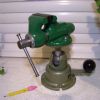
| SillyOldDuffer | 06/12/2016 09:56:18 |
| 10668 forum posts 2415 photos | Posted by Christine Walker on 06/12/2016 09:09:25:
Chaps - I have managed to find out the spindle nose is 39 x 4mm... whatever that means. 20mm hole through spindle. Forgive the stupid question, but would a chuck with a 1"1/4 x 12 TPI fit? Christine Probably not. A photo would help if you have the wherewithal. I'm not familiar with your particular lathe but it looks to be one of the Mini-lathe family. These usually have bolt on chucks rather than a screw-fit type. In the picture below two of the three nuts securing a bolt on chuck can be seen sandwiched between the back of the chuck and the headstock.
Put a book or lump of wood under the chuck to protect the ways if the chuck drops off when you undo the nuts. It's likely to be a tight fit and you may have to gently lever the chuck off. Next step is to find a 4-jaw chuck that fits the flange on your particular lathe. The flange will have a register and 3 or 4 holes in it. Your looking for a match to the register diameter and the holes. Sometimes a backplate converter is needed. The good news is that ArcEuroTrade and others all carry good ranges of bolt-on chucks. With luck a CJ0623B owner will be along to advise: if not, I'd ring Amadeal and ask if they have a 4jaw chuck to fit the CJ0623b - they used to sell it. The easiest way to centre work in a 4 jaw chuck is with a Dial Indicator and Stand. I blanched at the cost but it's worth it. Dave |
| KWIL | 06/12/2016 11:01:06 |
| 3681 forum posts 70 photos | Operators manual with data |
| Mike E. | 06/12/2016 11:41:58 |
 217 forum posts 24 photos | When a faceplate is attached to a lathe, a one time facing cut is taken to make sure it runs true. Are you sure that he plywood attached to your faceplate also runs true ? Reading these posts I'm wondering if the "plywood" is the problem ? Unlike metal, if an item is attached to plywood it may compress unevenly causing a small unperceived wobble causing you indicating issues, something to consider. |
| Les Jones 1 | 06/12/2016 12:27:07 |
| 2292 forum posts 159 photos | Hi Christine, Les. |
| Ajohnw | 06/12/2016 12:45:45 |
| 3631 forum posts 160 photos | The details I can find suggest that the lathe may have a 1 1/2" by 8 tpi spindle nose or 39x4mm. It looks like Chester Machine tools did sell them so there is a slight chance that they can help with a 4 jaw. No way does 1 1/2" - 39mm so you may be able to tell which by measuring it. It wouldn't be a bad idea to check the thread pitch with screw gauges as well The swing over the cross slide seems to be 5 5/16" or 135mm so a 5" or 125mm 4 jaw should be ok but a 100mm or 4" one could be used with the jaws sticking out a bit. I'd tend to go for the larger size for a 4 jaw. Really for this sort of thing you would have been better off setting up pretty central and then machining both the outside diameter and the groove. There is one other way of doing this sort of thing if there can be a hole in the middle of the disk. For this size chuck some 1" bar, turn a 1/2 dia spigot leaving a square shoulder. Run a dia part way down the spigot. You then need some large washers to clamp the work between. They could be square pieces of plate of some sort. Maybe even ply but aluminium or steel would be better. Double sided sticky tape could help of ply was used but it can be a pain to part afterwards. John - |
| Christine Walker | 06/12/2016 13:24:35 |
| 37 forum posts | Hi Les - The problem is, I have the ply mounted to the faceplate with four bolts. Then, in the centre (or what I hoped was the centre!) is a M10 hole. Through this hole, an M10 bolt passes, which also passes through the workpiece in the centre (or again, what I hoped was the centre). There is no other way to hold the workplace than like this. It is too big for chuck jaws and dogs on the face plate. (It's about 10mm dia bigger than the faceplate). Therefore, somewhere in that centring hole I have done something slightly wrong, but checking and double checking, I can't see where. Hi Ajohnw - I have mounted it though the centre (as explained above). However, I didn't have the O ring at that point (awaiting delivery) so had to remove the work piece to do something else. I remounted it, but then found there is this difference when I am machining end on. I don't know why. I can't fathom it. Something, somewhere isn't centred. MikeE - It could be the ply. Because I have checked the workpiece all over and it is perfect according to my digital callipers. But then again, the ply appears to be too! Thanks all C
|
| Les Jones 1 | 06/12/2016 15:11:14 |
| 2292 forum posts 159 photos | Hi Christine, Les. |


Please login to post a reply.
Magazine Locator
Want the latest issue of Model Engineer or Model Engineers' Workshop? Use our magazine locator links to find your nearest stockist!
Sign up to our Newsletter
Sign up to our newsletter and get a free digital issue.
You can unsubscribe at anytime. View our privacy policy at www.mortons.co.uk/privacy
Latest Forum Posts
- *Oct 2023: FORUM MIGRATION TIMELINE*
05/10/2023 07:57:11 - Making ER11 collet chuck
05/10/2023 07:56:24 - What did you do today? 2023
05/10/2023 07:25:01 - Orrery
05/10/2023 06:00:41 - Wera hand-tools
05/10/2023 05:47:07 - New member
05/10/2023 04:40:11 - Problems with external pot on at1 vfd
05/10/2023 00:06:32 - Drain plug
04/10/2023 23:36:17 - digi phase converter for 10 machines.....
04/10/2023 23:13:48 - Winter Storage Of Locomotives
04/10/2023 21:02:11 - More Latest Posts...
- View All Topics
Support Our Partners


Shopping Partners
Subscription Offer

Latest "For Sale" Ads
- Reeves** - Rebuilt Royal Scot by Martin Evans
by John Broughton
£300.00 - BRITANNIA 5" GAUGE James Perrier
by Jon Seabright 1
£2,500.00 - Drill Grinder - for restoration
by Nigel Graham 2
£0.00 - WARCO WM18 MILLING MACHINE
by Alex Chudley
£1,200.00 - MYFORD SUPER 7 LATHE
by Alex Chudley
£2,000.00 - More "For Sale" Ads...
Latest "Wanted" Ads
- D1-3 backplate
by Michael Horley
Price Not Specified - fixed steady for a Colchester bantam mark1 800
by George Jervis
Price Not Specified - lbsc pansy
by JACK SIDEBOTHAM
Price Not Specified - Pratt Burnerd multifit chuck key.
by Tim Riome
Price Not Specified - BANDSAW BLADE WELDER
by HUGH
Price Not Specified - More "Wanted" Ads...
Get In Touch!
Do you want to contact the Model Engineer and Model Engineers' Workshop team?
You can contact us by phone, mail or email about the magazines including becoming a contributor, submitting reader's letters or making queries about articles. You can also get in touch about this website, advertising or other general issues.
Click THIS LINK for full contact details.
For subscription issues please see THIS LINK.
Digital Back Issues


Donate

 Register
 Log-in
Model Engineer Magazine
- Percival Marshall
- M.E. History
- LittleLEC
- M.E. Clock

ME Workshop
- An Adcock
- & Shipley
- Horizontal
- Mill

Subscribe Now
- Great savings
- Delivered to your door

Pre-order your copy!
- Delivered to your doorstep!
- Free UK delivery!
All Forum Topics > Help and Assistance! (Offered or Wanted) > Centre help!!!