Forum sponsored by:

Tailstock Alignment
| Paul Lousick | 20/09/2016 12:44:08 |
| 2276 forum posts 801 photos | The suggested method for aligning the tailstock centre on a lathe is to make a test bar (stepped down in the centre) and to machine both ends without adjusting the cross slide. Then measure the diameter of both ends. The centres will be accurately aligned when the diameter of both ends is the same. (see top drawing arrangement below). This may take many trial cuts before the 2 ends are the same diameter. Why not just turn a diameter on one end only. Take a reading with a dial indicator attached to the tool post. Reverse the test bar between centres. Move the toolpost to the tailpost end without moving the cross slide and then align the tailstock until the DI reads the same as when it was at the headstock end. Double check DI measurements at headstock after moving tailstock. No extra cuts necessary. Your comments please, Paul.
Edited By Paul Lousick on 20/09/2016 12:45:20 |
| not done it yet | 20/09/2016 13:40:45 |
| 7517 forum posts 20 photos | For starters, why try to measure only half when you could be measuring twice as much difference? |
| Brian Wood | 20/09/2016 13:43:40 |
| 2742 forum posts 39 photos | Hello Paul, |
| Paul Lousick | 20/09/2016 14:16:28 |
| 2276 forum posts 801 photos | (why try to measure only half when you could be measuring twice as much difference?) More accurate, Yes. But if you have a precision ground test bar do you re-machine it each time you re-align the tailstock or use a DTI as in the second example ? Hi Brian, Yes, DTI's are comparators, but that is exactly what is being done. Comparing the distance from a common datum. When the mesurements are the same, the centres must be aligned. Accuracy would depend on the precision of the DTI, and similarly on the accuracy of a micrometer. As you have said, it will be interesting what others think. There is probably a good reason to use the conventional method and measure both ends of the test bar. Paul. |
| Antony Price | 20/09/2016 14:34:54 |
| 36 forum posts 29 photos | Hi Paul
You might want to think about this, that I found this on YouTube. I haven't had a chance to make one yet, but its high on my "To do" list Randy Richard In The Shop - Lathe Tail Stock Alignment Tool Demo
Tony |
| Martin Connelly | 20/09/2016 14:56:18 |
 2549 forum posts 235 photos | I think the machining of both ends is used when setting up a lathe to check for parallel turning. This machining of both ends will set the tailstock in the correct position for whatever the bed is doing in the way of twisting or the carriage responding to wear (at the distance the test bar determines). Once the test bar is made then setting the tailstock back to the correct position is, as stated above, just a case of fitting a suitable DTI to the carriage and checking you get the same reading at both machined sections of the test bar after moving the tailstock over. Martin
|
| Neil Wyatt | 20/09/2016 14:58:26 |
 19226 forum posts 749 photos 86 articles | Paul, Better still, turn both ends approximately to size. Take a skim off one end, reverse the bar and at the same setting skim the other end. They should now be the same to <1 thou no matter how crazy your lathe is. You can now set the bar between centres and just use an indicator to compare readings at each end. Whether diameter or radius doesn't matter - in fact the actual diameter of the bar doesn't matter. It makes it easy as you measure one end then just tweak the tailstock until the other end shows the same reading. Simples. Neil & his bar:
|
| Iain Downs | 20/09/2016 18:39:12 |
| 976 forum posts 805 photos | I made one of Neil's clever bars and it seems to work well. Not as nicely finished of course, but what can you do?
Iain |
| mark smith 20 | 20/09/2016 19:02:59 |
| 682 forum posts 337 photos | Paul , i believe this guy is doing what you describe in this video. |
| Paul Lousick | 20/09/2016 23:17:34 |
| 2276 forum posts 801 photos | Neil, Similar idea but instead of reversing the bar for machining, reversing the bar for measuring. Mark, Same idea as in the video. I have seen both methods in lathe set-up instructions but thought I would throw it into the forum for your thoughts. Comparing a measurement with a dial indicator at both ends is a quick way of checking the tailstock alignment for everyday turning jobs but I believe that the best test is in "the tasting of the pudding" ie. actually machining a bar where the cutting tool is under pressure and any slop in the guides is eliminated. Thanks for your feedback, Paul.
|
| Hopper | 21/09/2016 05:22:40 |
 7881 forum posts 397 photos | Posted by Paul Lousick on 20/09/2016 23:17:34:
...the best test is in "the tasting of the pudding" ie. actually machining a bar where the cutting tool is under pressure and any slop in the guides is eliminated...
^^^^ This. The other tests are all preparation for doing the real world test, turning a piece of bar under actual working conditions and seeing how it comes out. The other thing is that the tailstock horizontal set up is the absolute last of a series of set ups to get the lathe running right. It comes after making right the headstock bearings, bed (lack of) twist, carriage ways and gibs, cross slide ways and gibs, topslide ways and gibs and tailstock height and tail stock alignment to lathe main axis. There can be a lot of accumulated error to remove among that lot. |
| Tim Stevens | 21/09/2016 10:20:25 |
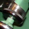
 1779 forum posts 1 photos | Further to Brian Wood's comment - third message in this strand, inviting comments. It is my understanding that there are two types of dial-type checking devices. They are the plunger type and the lever type, called respectively Dial Gauge and Dial Test Indicator (but sometimes misapplied). The plunger type gauge moves a rack against a pinion on the pointer, and plunger movement is proportional to what the dial shows over the whole range - and this is what the OP shows in his picture. The lever type gives a slightly varied proportionality because the lever is more effective when the tip moves at right angles to the work, ie only over a small 'middle' section of a reading. So, the DTI is a comparison, but the DG is a measuring tool (so I am not in accord with Brian Wood on this). Who is right, please? PS I am not trying to score points over anyone, but I am hoping to make all our messages clear and unambiguous. Regards, Tim |
| Steamer1915 | 21/09/2016 11:21:14 |
 171 forum posts 42 photos | Posted by Tim Stevens on 21/09/2016 10:20:25:
The lever type gives a slightly varied proportionality because the lever is more effective when the tip moves at right angles to the work, ie only over a small 'middle' section of a reading.
There are styli available for some lever "clocks" that are tear drop shaped to compensate for Cosine error. I believe that this may be an involute shape. Best regards, Steve. Edited By Steamer1915 on 21/09/2016 11:22:52 Edited By Steamer1915 on 21/09/2016 11:24:45 |
| Michael Gilligan | 21/09/2016 11:35:24 |
 23121 forum posts 1360 photos | Posted by Tim Stevens on 21/09/2016 10:20:25:
So, the DTI is a comparison, but the DG is a measuring tool (so I am not in accord with Brian Wood on this). Who is right, please? . Tim, My understanding [which may, or may not, be in accord with others'] is that both of the devices you have described are Indicators; because they reference a non-fixed zero point. Subject to other factors, such as linearity, an Indicator can become a Gauge if it has a fixed 'Anvil' of some sort, to work against. ... The common Micrometer, for example, is a gauge because of its frame and anvil; but a micrometer head is only a comparator. That's how it works for me ... Would anyone care to give a better distinction? MichaelG. |


Please login to post a reply.
Magazine Locator
Want the latest issue of Model Engineer or Model Engineers' Workshop? Use our magazine locator links to find your nearest stockist!
Sign up to our Newsletter
Sign up to our newsletter and get a free digital issue.
You can unsubscribe at anytime. View our privacy policy at www.mortons.co.uk/privacy
Latest Forum Posts
- *Oct 2023: FORUM MIGRATION TIMELINE*
05/10/2023 07:57:11 - Making ER11 collet chuck
05/10/2023 07:56:24 - What did you do today? 2023
05/10/2023 07:25:01 - Orrery
05/10/2023 06:00:41 - Wera hand-tools
05/10/2023 05:47:07 - New member
05/10/2023 04:40:11 - Problems with external pot on at1 vfd
05/10/2023 00:06:32 - Drain plug
04/10/2023 23:36:17 - digi phase converter for 10 machines.....
04/10/2023 23:13:48 - Winter Storage Of Locomotives
04/10/2023 21:02:11 - More Latest Posts...
- View All Topics
Support Our Partners


Shopping Partners
Subscription Offer

Latest "For Sale" Ads
- Reeves** - Rebuilt Royal Scot by Martin Evans
by John Broughton
£300.00 - BRITANNIA 5" GAUGE James Perrier
by Jon Seabright 1
£2,500.00 - Drill Grinder - for restoration
by Nigel Graham 2
£0.00 - WARCO WM18 MILLING MACHINE
by Alex Chudley
£1,200.00 - MYFORD SUPER 7 LATHE
by Alex Chudley
£2,000.00 - More "For Sale" Ads...
Latest "Wanted" Ads
- D1-3 backplate
by Michael Horley
Price Not Specified - fixed steady for a Colchester bantam mark1 800
by George Jervis
Price Not Specified - lbsc pansy
by JACK SIDEBOTHAM
Price Not Specified - Pratt Burnerd multifit chuck key.
by Tim Riome
Price Not Specified - BANDSAW BLADE WELDER
by HUGH
Price Not Specified - More "Wanted" Ads...
Get In Touch!
Do you want to contact the Model Engineer and Model Engineers' Workshop team?
You can contact us by phone, mail or email about the magazines including becoming a contributor, submitting reader's letters or making queries about articles. You can also get in touch about this website, advertising or other general issues.
Click THIS LINK for full contact details.
For subscription issues please see THIS LINK.
Digital Back Issues


Donate

 Register
 Log-in
Model Engineer Magazine
- Percival Marshall
- M.E. History
- LittleLEC
- M.E. Clock

ME Workshop
- An Adcock
- & Shipley
- Horizontal
- Mill

Subscribe Now
- Great savings
- Delivered to your door

Pre-order your copy!
- Delivered to your doorstep!
- Free UK delivery!
All Forum Topics > General Questions > Tailstock Alignment