Forum sponsored by:

Modded 1" Minnie Progress
| Richard S2 | 01/07/2016 18:03:14 |
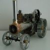 237 forum posts 135 photos | Returned to this first ever project after 25 years, as I now have time to finish it with the intention of firing it up later this year before prepping for paint. Made a lot of extra work for myself with several changes to Mr Mason's excellent design and increased the level of detail. I worked to his drawings for the rear wheels showing 36 Strakes, instead of his written description of 35.
Main 'working' changes were the Con Rod, Motion Bracket/Ass'y, and Reverse Lever/Rod layout. Geometry is as per original design.
3rd and Final Gears have additional machining. Scrapped the Brass Tender in favour of Brass lined straight backed Steel design of the 1890's.
I won't list all of the changes, as those who are building, or have built this Model will see for themselves in the pics.
Nearly at the point where I will start dismantling it to finish, make and fit some other parts ready for the final assembly One thing I have to do at some point is to test the 'Scaled Down' Water Lifter to check the Nozzle angles etc are correct while off the Engine. The Boiler is not my own work. I purchased it in 1986 (Morewood's) and has the 5 bolt fixing into oversized Stays. I did not have the skills or equipment to make my own at the time. So I have respect for those who have made, or are making their own. Regards
|
| Neil Wyatt | 01/07/2016 18:33:36 |
 19226 forum posts 749 photos 86 articles | Beautiful workmanship. I have to wonder HOW anyone could make a 35-spoke wheel with staggered spokes... Neil |
| SillyOldDuffer | 01/07/2016 19:23:32 |
| 10668 forum posts 2415 photos | Gorgeous! |
| Michael Gilligan | 01/07/2016 19:31:27 |
 23121 forum posts 1360 photos | Great work, and excellent photos MichaelG. |
| JasonB | 01/07/2016 20:22:52 |
 25215 forum posts 3105 photos 1 articles | Strakes Neil, not spokes.
That is a very nice engine indeed, motion has the look of a Fowler about it and the hornplate mounted pump is a good idea. As you say to those that know the the model the more you look the more details you see
Will you paint and steam it or keep it in the bright state and dirt free? |
| Richard S2 | 01/07/2016 23:28:34 |
237 forum posts 135 photos | Posted by JasonB on 01/07/2016 20:22:52:
That is a very nice engine indeed, motion has the look of a Fowler about it and the hornplate mounted pump is a good idea. As you say to those that know the the model the more you look the more details you see Will you paint and steam it or keep it in the bright state and dirt free? Thanks All, sorry about the pics with the lack of Depth of Field Focus in macro as my digital camera is 12 years old. Hope it inspires some to enhance basic designs. I love detail and precision. Yes Jason, I will paint it........ reluctantly!. It will be tested on air initially, thoroughly checked and steamed. I will then clean and prep it for painting. Spooky you mention Fowler!, as years ago I took pics of several at shows for reference and back in 87, I purchased the Etch Primer, Matt Black and Fowler Prussian Blue Gloss Enamels along with Brushing, Airbrush and Etch Thinners from Precision Paints as they were then. I had wrapped them up unopened and sealed them in a large Coffee tin for storage for when ready to paint...... I opened the tin last week I have a question if someone can advise. The Boiler has a Manufacturer's Certificate and the numbers are correct. Am I right in saying I will have to have it checked and re-certified for use when I have finished it?. I would prefer it to be compliant if I have to sell it. Thanks. Regards. (edited for spelling)
Edited By Richard S2 on 01/07/2016 23:34:06 |
| julian atkins | 01/07/2016 23:46:05 |
 1285 forum posts 353 photos | Hi Richard, Minnie was discussed in somewhat forthright terms (my own fault) on the modeleng proboards forum recently. I do not want to detract from the superb job you have done, but I would be somewhat hesitent to expect too much in the way of performance if built to the drawings. You will need a new club hydraulic boiler test but to 1.5 times working pressure as opposed to 2 times working pressure. A club steam test pressure test will also be required to working pressure. The original 2 times working pressure hydraulic certificate from the commercial builder should still be valid and accepted by your club. If not then you have to go through the procedure from the start and with the club boiler inspector excercising his discretion. Obviously you have to be a member of a club. Cheers, Julian |
| Richard S2 | 02/07/2016 14:22:17 |
237 forum posts 135 photos |
Posted by julian atkins on 01/07/2016 23:46:05: Hi Richard, Minnie was discussed in somewhat forthright terms (my own fault) on the modeleng proboards forum recently. I do not want to detract from the superb job you have done, but I would be somewhat hesitant to expect too much in the way of performance if built to the drawings. Cheers, Julian Hello Julian, thanks, I'm not familiar with that Forum, will have to search it out. Forthright terms are fine with me. I respect expertise in a 'Specialist Field' and am not easily offended. I was/am ignorant of Small T.E Boiler designs and chose this one purely as a first venture into M.E interests and what info was around on them 32 years ago. The size was also an important consideration. I have no problem persevering with any effort to obtain a reasonable 'Steaming' performance from it when finished, purely to see it operate in it's purposeful form. My main enjoyment has been the learning and operations processes to make the parts accurately with only books to learn from and practice. As for the Certification process info you furnished, you've provided all I need to know, so thanks for that. I had a chance to take some more full view images of it's current state in natural available light-
Regards |
| Roderick Jenkins | 02/07/2016 15:51:53 |
 2376 forum posts 800 photos | Thanks for sharing those pics of the complete model - very, very nice. That really is an inspiration for my build - whenever I get it started Rod |
| David Murray 1 | 03/07/2016 18:37:01 |
| 20 forum posts |
Richard What a stunning example of Minnie. Fantastic workmanship and a lot of details cannot have been easy in this small scale. I am just in the process of steaming my own Minnie and running her for the first few times. Plenty of teething troubles along the way but she makes steam like it is going out of fashion! The water pump is my biggest headache which will not deliver. I've rigged up a temporary handpump and you can keep her in steam fro as long as you like. I will be taking the pump off and doing some more investigation. Here's a little video of my latest steam test last week with the handpump just out of shot. |
| Richard S2 | 07/07/2016 20:54:54 |
237 forum posts 135 photos | Thanks Rod, hope you get as much enjoyment from it as I have done with this Engine. Thanks David, not sure if I've gone over the top with details, but the challenges it throws up are the bits I like about it.........Small production work example-
0.0669" (1.62mm) is the smallest AF Steel Hex stock I have and managed to produce some 12BA nuts and bolts, along with other sizes. Thanks for the link and good to see it running, nice work. Hope you overcome the few problems with the pump. Regards
|
| Richard S2 | 31/07/2016 20:51:38 |
237 forum posts 135 photos | Always thought the Minnie front end looked rather open and sparse, maybe because I chose to machine the Axle to a square section either side of the pivot point , so I have been toying with a Spud Ring/Pan layout to see if it looked ok?-
I think I'll keep it on, so just needs finishing off and a Spud Pan to make and fit. I shall probably call it a day then with any more changes
|
| David Bothwell 1 | 11/09/2016 15:41:56 |
| 204 forum posts | Wow! Makes me think about giving up! Well done Richard! Did you make drawings for the motion changes or just used photo research? Could you post a picture of the left side motion works? Considering your changes to my model |
| Richard S2 | 16/09/2016 23:03:49 |
237 forum posts 135 photos | Posted by David Bothwell 1 on 11/09/2016 15:41:56:
Wow! Makes me think about giving up! Well done Richard! Did you make drawings for the motion changes or just used photo research? Could you post a picture of the left side motion works? Considering your changes to my model Hi David, Sorry for the delay in response, busy restoring a 1970s American Mower Deck. I did make some rough feint drawings on slightly better material than a Fag Packet!. I will try and take a pic of them and the left side as you requested as asap. I used all of the dimensions of the original drawings to place the Shaft centres of my Cylinder in position on my boiler onto paper drawn in 2 dimensions:- end-on and side view. I then drew in the new Motion Bracket to fit the original Bracket Saddle with a few mods to fit them together. The challenge for me. being a 'Newbie Dabbler' at the time, was to consider order of machining etc and assembly, so I often visualised it in my head and noted the procedures down as a check list. I think I had to apply a 0.002" shim to the lower Slide Bar Pad face to cure misalignment when the bolt was fitted. Slide Bars machined from 1/2" x 1/2" x 1/8" BMS. The Motion Bracket was cut from 3/16" BMS Plate and the 2 Pads pinned and Hard Soldered. Regards
|
| David Bothwell 1 | 17/09/2016 16:47:30 |
| 204 forum posts | Many thanks Richard for talking time to respond, Had a few problems with this model (which I purchased/part exed) and part made, spent today making a new valve and buckle as the old one was a mess. Thanks for the detailed explanation and I am still thinking about the alterations. I have found a piece of angle iron, a bit over size which could be used, any further info would be gratefully received but I dont expect you drop everything to accomodate me! |
| David Bothwell 1 | 17/09/2016 16:51:15 |
| 204 forum posts | Many thanks Richard for talking time to respond, Had a few problems with this model (which I purchased/part exed) and part made, spent today making a new valve and buckle as the old one was a mess. Thanks for the detailed explanation and I am still thinking about the alterations. I have found a piece of angle iron, a bit over size which could be used, any further info would be gratefully received but I dont expect you drop everything to accomodate me! |
| Richard S2 | 17/09/2016 21:29:18 |
237 forum posts 135 photos |
No problem David, I've managed to produce reasonable images that may help you with your plan as requested. Please note that I did all this work about 27 years ago, so even I would have to think how I went about some procedures, Hope the rough drawings make sense. Couple of things to note are that the Weighshaft has to partly pass through the lower Guide Bar and Pad. The Weighshaft bearing tube has to be cut away in that area also-
And the pics, sorry about it being a bit dusty-
One thing to bear in mind is that my Motion Bracket Saddle Casting was machined to account for this modification, so I left as much 'Meat' on it as possible initially..
Hope these help. Regards. Edited By Richard S2 on 17/09/2016 21:31:20 Edited By Richard S2 on 17/09/2016 21:31:43 |
| David Bothwell 1 | 18/09/2016 12:17:58 |
| 204 forum posts | Many thanks for your trouble, still trying to finish mine after much re-work! Thats the trouble witn acquiring part made models. Could have probably made it as quick from scratch (apart from the wheels maybe) |
| Brian Abbott | 10/11/2016 23:40:59 |
 523 forum posts 95 photos | Hello Richard, Could i ask how you did the lettering on the wheel hubs ? I have been looking at doing something similar, a friend of mine suggested using an acid etch. Thanks in advance, Brian |
| Richard S2 | 11/11/2016 18:40:52 |
237 forum posts 135 photos | Hi Brian, Good to see you making progress on yours. Yes of course, happy to explain what I did. My intention was to produce the same result as proper 'cast-in' lettered castings as on the full size, but with simulated maker info, so I put my name and location on (before they split Sussex into East and West). My inspiration for this was when I was at the 1986 ME Exhibition, I found a Stand (Model Shop) with a range of Etched Brass Lettering Sheets. I found one that contained just the right sizes made by - The smallest size is 1.5mm and the biggest is 4mm. I used 1.5, 2 and 3mm letters. Even 30 years ago, I had to use a Jeweller's Loupe to see while I carefully cut them from the Sprues/Sheet . Firstly, I cleaned the reverse of the sheet area with White Wine Vinegar to de-grease and then 'Tinned' the required letters using Solder Paste before cutting off. Having measured the thickness of the Etched Letters, I made Hub Covers and Smoke Box Door Plate with recesses a tad less than the tinned letters (few thousandth of an inch). I also lightly 'Tinned' these recesses where I wanted the lettering. Placed the Lettering as required with tiny dabs of Flux. then laid a piece of thin, flat, heavily tarnished copper to keep the letters in place while I applied the heat to re-melt the 'Tinning'. To give you an idea of the 'Tinning' thickness, is to tin a piece of brass and lightly wipe off the excess, leaving a shiny smooth surface. Too much, and the letter centres and edges will flood when joining and leave no space for paint depth.. All worked first time and just needed a scrub to remove the Flux residues. Applied a thin coat of enamel paint and left to harden for a week. Finally cleaned back the paint to the Brass lettering and raised boundary lines using P600 wet or Dry and Washing liquid on a piece of glass, followed by a polish.. Solder paste is/was 188c with Active Flux. As luck will have it, I searched for Scale Link and still exists in it's next generation guise, but not located in Middlesex anymore. Here is a link if you want the same sort of lettering which is about half way down the page- The Valve Chest Cover Plate Letters are 3mm , 2mm and 1.5mm . I have more to do on that and find a way to make a Number Plate showing my Boiler Number, similar to the Allchin Number Plate. Problem is, these sheets don't include numbers, so I'll have to mess with them. Hope this helps. Regards |


Please login to post a reply.
Magazine Locator
Want the latest issue of Model Engineer or Model Engineers' Workshop? Use our magazine locator links to find your nearest stockist!
Sign up to our Newsletter
Sign up to our newsletter and get a free digital issue.
You can unsubscribe at anytime. View our privacy policy at www.mortons.co.uk/privacy
Latest Forum Posts
- *Oct 2023: FORUM MIGRATION TIMELINE*
05/10/2023 07:57:11 - Making ER11 collet chuck
05/10/2023 07:56:24 - What did you do today? 2023
05/10/2023 07:25:01 - Orrery
05/10/2023 06:00:41 - Wera hand-tools
05/10/2023 05:47:07 - New member
05/10/2023 04:40:11 - Problems with external pot on at1 vfd
05/10/2023 00:06:32 - Drain plug
04/10/2023 23:36:17 - digi phase converter for 10 machines.....
04/10/2023 23:13:48 - Winter Storage Of Locomotives
04/10/2023 21:02:11 - More Latest Posts...
- View All Topics
Support Our Partners


Shopping Partners
Subscription Offer

Latest "For Sale" Ads
- Reeves** - Rebuilt Royal Scot by Martin Evans
by John Broughton
£300.00 - BRITANNIA 5" GAUGE James Perrier
by Jon Seabright 1
£2,500.00 - Drill Grinder - for restoration
by Nigel Graham 2
£0.00 - WARCO WM18 MILLING MACHINE
by Alex Chudley
£1,200.00 - MYFORD SUPER 7 LATHE
by Alex Chudley
£2,000.00 - More "For Sale" Ads...
Latest "Wanted" Ads
- D1-3 backplate
by Michael Horley
Price Not Specified - fixed steady for a Colchester bantam mark1 800
by George Jervis
Price Not Specified - lbsc pansy
by JACK SIDEBOTHAM
Price Not Specified - Pratt Burnerd multifit chuck key.
by Tim Riome
Price Not Specified - BANDSAW BLADE WELDER
by HUGH
Price Not Specified - More "Wanted" Ads...
Get In Touch!
Do you want to contact the Model Engineer and Model Engineers' Workshop team?
You can contact us by phone, mail or email about the magazines including becoming a contributor, submitting reader's letters or making queries about articles. You can also get in touch about this website, advertising or other general issues.
Click THIS LINK for full contact details.
For subscription issues please see THIS LINK.
Digital Back Issues


Donate

 Register
 Log-in
Model Engineer Magazine
- Percival Marshall
- M.E. History
- LittleLEC
- M.E. Clock

ME Workshop
- An Adcock
- & Shipley
- Horizontal
- Mill

Subscribe Now
- Great savings
- Delivered to your door

Pre-order your copy!
- Delivered to your doorstep!
- Free UK delivery!
All Forum Topics > Traction engines > Modded 1" Minnie Progress