Forum sponsored by:

Formulae required
| John Stevenson | 10/12/2015 22:06:31 |
 5068 forum posts 3 photos | Next week I have a long rack to make, about 1M long. At the moment I'm awaiting material as it non standard sized brass.
I have done these before ages ago up to 1.5M long. Cutting the teeth is no problem I have a program on the CNC for this to do 1/2M at a time and move the blank.
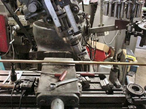
On the rear of the rack is a radius so it can bolt onto a circular linear tube which the rack drives up and down. The tube is 75mm in diameter. The last ones I did I used the boring head in the mill with the head set over at an angle.
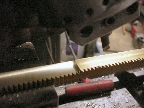
And close up.
The idea being that if the head is vertical you get a vertical hole and if the head is horizontal you get a horizontal hole so Gordon Bennett tells us that anywhere in between is an ellipse which over 16mm for the unwashed is an arc.
So the question is what is the formulae to sort out this 37.5mm radius. I did find it on a web page but have since lost it. From memory the formula took into account the radius of the boring tool and the tilt angle. |
| Clive Foster | 10/12/2015 23:15:44 |
| 3630 forum posts 128 photos | Head angle 45°, boring tool set to cut radius of arc. Same as cutting a part spherical depression. Boring tool sweeps out the rim of a section through the centre of a sphere which must be a circle. Clive P.S. Asking on Practical Machinist as well is cheating. Early enough over there that their brains are still awake not shutting down for bed-time. Ought to have mremebered the lens makers equation tho' as I programmed a BBC B to figure that out for the optics shop "not telling you how many" years ago. (Adcok Shpleys lens tooling version od the 1ES is one wierd looking beast.) Edited By Clive Foster on 10/12/2015 23:24:36 |
| Emgee | 10/12/2015 23:22:11 |
| 2610 forum posts 312 photos | John, Won't the radius of cut remain at 37.5 rad regardless of angle of the head ? Emgee Does this page help ? 1728.org/circsect.htm
Edited By Emgee on 10/12/2015 23:40:29 |
| Phil P | 10/12/2015 23:41:25 |
| 851 forum posts 206 photos | John I just turned this up with a quick google search sin C = D/2Rc
Phil |
| John Stevenson | 10/12/2015 23:41:36 |
5068 forum posts 3 photos | Clive the lens making formulae isn't any good I know the radius. What I want is the angle to tilt the head. It can't be 45 degrees as from the earlier example which used the same linear tube that head is nowhere near 45 degrees.
I think Marv Klotz has a formula in his DOS based programs but it will take me too long to sort out how to run this. Reading A Treatise on Milling by Brown and sharp at the moment, might have been in there. |
| Roger Head | 10/12/2015 23:44:08 |
| 209 forum posts 7 photos | Clive, I've never made a cut like this, but surely the actual depth of the cut (i.e. from the edges of the rack to the trough in the centre) will be less than would be made if the boring tool was run horizontally. Because it can't be run horizontally for such a small radius cut, the angled-head is used, but the radius set on the boring head needs to be smaller than the desired radius of the cut. Without going through the geometry with a pencil and paper, I'd guess that for a 45deg angle of the head, the boring radius would be something like 1/root2 (i.e. 0.707) of the desired radius. So that would mean setting the boring tool to 26.51mm. No guarantees! Roger
Edited By Roger Head on 10/12/2015 23:44:39 |
| John Stevenson | 10/12/2015 23:46:29 |
5068 forum posts 3 photos | Phil, Bugger it, my copy only has 406 pages |
| Phil P | 10/12/2015 23:50:31 |
| 851 forum posts 206 photos | John Here's another http://www.angelfire.com/ks/mcguirk/generatingradius.html My dad used this technique to make new wood blocks for the rear wheels of our Fowler road loco. He used a big slitting saw tilted over to end up with a curve in the block to fit a 7 foot diameter wheel. Phil |
| John Stevenson | 11/12/2015 00:04:30 |
5068 forum posts 3 photos | Phil, That's the page I saw originally and it's the same as the formula you quoted only one uses diameter and one uses radius.
So a tool at 15mm rad and tube at 37.5 = 23.5 degrees which looks right for the picture
For the head to be at 45 degrees the cutter diameter need to be 53mm [ 53 / 75 = 0.707 approx ] Edited By John Stevenson on 11/12/2015 00:06:10 |
| Ajohnw | 11/12/2015 09:07:26 |
| 3631 forum posts 160 photos | The same technique is used to initially grind telescope mirrors and lenses. Convex or concave. I think it also slightly relates to how snooker balls are made. John - |
| Roger Head | 11/12/2015 11:07:16 |
| 209 forum posts 7 photos | JS, as you probably know, the above formula are only approximate. I think that I have sorted the exact equation, as shown below. As you can see, the second-order effects only become significant when a reduction in the cutter radius approaches (channel width / 2) . In your case w/2 is 8mm and your cutter radius is 15mm, so the error in the approximation is small (~23.7deg vs exact 21.9xxxdeg), leading to a channel width that is approx 0.25mm narrower than your 16mm rack. Alternatively, if you advance the cutter until it occupies the full 16mm width, the channel depth will be marginally greater. But in the greater scheme of things, it will hardly matter. The only real use of this is to emphasize that the simple approximation is just that, and to illustrate the effect of reducing the actual cutter radius too far. Roger (E&OE
Edited By Roger Head on 11/12/2015 11:09:28 |
| Roger Head | 11/12/2015 11:50:20 |
| 209 forum posts 7 photos | Phil P "Exquisitely covered in A Treatise On Milling and Milling Machines, Third Edition (1951), Page 583" Any chance that you could scan/copy/xxx that bit, and post it? Thanks, Roger
|
| Phil P | 11/12/2015 12:58:04 |
| 851 forum posts 206 photos | Roger I didn't find it in the book myself, I just googled it and that is what came up. I probably do have the book but I will have to check when I am at home. Phil |
| Michael Gilligan | 11/12/2015 13:55:12 |
 23121 forum posts 1360 photos | As the Season of GoodWill is upon us ... Try here Individual pages are downloadable as PDF, without 'Partner login' MichaelG. |
| Muzzer | 11/12/2015 13:56:20 |
 2904 forum posts 448 photos | Hmm. The path cut by the cutter will be elliptical, not circular, so this method will only give an approximation of a cylindrical surface. Probably not a massive issue if the rack only subtends a small angle at the centre of the tube ie its width is quite a bit smaller than the diameter of the tube. The only way to get a "good" fit would be to have the cutter axis completely parallel to the rack. Might be a problem with a Bridgeport, although IIRC, you have a horizontal (angle) head that would do the trick? If you want to avoid the rack rocking on the tube, you'd want to err on the side of having a smaller radius on the rack. That way it will sit on the outer edges of the curved face of the rack. Murray |
| John Stevenson | 11/12/2015 14:24:35 |
5068 forum posts 3 photos | Thanks for the input lads but lets not over think this. It screws to the tube every 150mm or so and there are two roll pins, one either end to supply position. The rack is driven by a tiny stepper motor to raise and lower a transducer into a bath of water as part of Mr Rollsy Royce's crack testing gear. The linear tube is counter balanced so the loads on this tiny rack are minimal.
This is the third rack I have done over a period of about 15 years and they must have over a dozen tanks. |
| jason udall | 11/12/2015 16:15:47 |
| 2032 forum posts 41 photos | Ball nose cutter? |
| John Stevenson | 11/12/2015 16:52:40 |
5068 forum posts 3 photos | 75mm ball nosed cutter to do a one off job ? |
| Neil Wyatt | 11/12/2015 17:47:45 |
 19226 forum posts 749 photos 86 articles | Posted by John Stevenson on 11/12/2015 16:52:40:
75mm ball nosed cutter to do a one off job ? Brass rack? You could have made a silver steel one to do the job by now |
| John Stevenson | 11/12/2015 18:16:13 |
5068 forum posts 3 photos | 75mm silver steel ????????????????????????
I'm nearly a bloody pensioner you know [ no bus pass ] |


Please login to post a reply.
Magazine Locator
Want the latest issue of Model Engineer or Model Engineers' Workshop? Use our magazine locator links to find your nearest stockist!
Sign up to our Newsletter
Sign up to our newsletter and get a free digital issue.
You can unsubscribe at anytime. View our privacy policy at www.mortons.co.uk/privacy
Latest Forum Posts
- *Oct 2023: FORUM MIGRATION TIMELINE*
05/10/2023 07:57:11 - Making ER11 collet chuck
05/10/2023 07:56:24 - What did you do today? 2023
05/10/2023 07:25:01 - Orrery
05/10/2023 06:00:41 - Wera hand-tools
05/10/2023 05:47:07 - New member
05/10/2023 04:40:11 - Problems with external pot on at1 vfd
05/10/2023 00:06:32 - Drain plug
04/10/2023 23:36:17 - digi phase converter for 10 machines.....
04/10/2023 23:13:48 - Winter Storage Of Locomotives
04/10/2023 21:02:11 - More Latest Posts...
- View All Topics
Support Our Partners


Shopping Partners
Subscription Offer

Latest "For Sale" Ads
- Reeves** - Rebuilt Royal Scot by Martin Evans
by John Broughton
£300.00 - BRITANNIA 5" GAUGE James Perrier
by Jon Seabright 1
£2,500.00 - Drill Grinder - for restoration
by Nigel Graham 2
£0.00 - WARCO WM18 MILLING MACHINE
by Alex Chudley
£1,200.00 - MYFORD SUPER 7 LATHE
by Alex Chudley
£2,000.00 - More "For Sale" Ads...
Latest "Wanted" Ads
- D1-3 backplate
by Michael Horley
Price Not Specified - fixed steady for a Colchester bantam mark1 800
by George Jervis
Price Not Specified - lbsc pansy
by JACK SIDEBOTHAM
Price Not Specified - Pratt Burnerd multifit chuck key.
by Tim Riome
Price Not Specified - BANDSAW BLADE WELDER
by HUGH
Price Not Specified - More "Wanted" Ads...
Get In Touch!
Do you want to contact the Model Engineer and Model Engineers' Workshop team?
You can contact us by phone, mail or email about the magazines including becoming a contributor, submitting reader's letters or making queries about articles. You can also get in touch about this website, advertising or other general issues.
Click THIS LINK for full contact details.
For subscription issues please see THIS LINK.
Digital Back Issues


Donate

 Register
 Log-in
Model Engineer Magazine
- Percival Marshall
- M.E. History
- LittleLEC
- M.E. Clock

ME Workshop
- An Adcock
- & Shipley
- Horizontal
- Mill

Subscribe Now
- Great savings
- Delivered to your door

Pre-order your copy!
- Delivered to your doorstep!
- Free UK delivery!
All Forum Topics > Workshop Techniques > Formulae required