Forum sponsored by:

Stirling Engine : Laura
A premilled kit by Bengs
| Brian John | 11/10/2015 07:39:26 |
| 1487 forum posts 582 photos | I have made a start on the Stirling engine kit ''Laura'' by Bengs. I thought I would tackle what I think might be the most difficult part first : the cranks. I intend to face off the brass work piece, reduce diameter to size, drill out centre hole, part off and polish the other face . Now I have to remove metal from two sides to get the correct shape. I was thinking of drilling a (say) 8mm hole to get the curve then cutting the rest away with a dremel tool. 1. Without a milling machine, how would you tackle this ? I do not intend to build this engine with a glass cylinder as per the original design. This will be replaced with an aluminium cylinder so I do not have to build a bullet shape piston to fit the glass tube. But I am curious how you would go about making a bullet shape in the lathe. 2. Do you just round off the end of the piston with a hand held file and do it by eye ?
Edited By Brian John on 11/10/2015 07:41:11 Edited By JasonB on 11/10/2015 07:57:47 Edited By Brian John on 11/10/2015 08:06:32 |
| JasonB | 11/10/2015 07:52:59 |
 25215 forum posts 3105 photos 1 articles | The 6H7 means it needs an accurate hole so dril smaller than 6.0mm and ream. Yes drill out the corners but saw and then file to shape, forget the Dremel. You may have problems with an aluminium cylinder expanding and loosing compression, there is a reason they suggest glass. Turn end roughly to profile and then file in the lathe, ideally a ball turning tool would be used |
| Brian John | 11/10/2015 08:10:18 |
| 1487 forum posts 582 photos | I use the dremel cutting wheel as a saw ; I find it quicker and tidier than a hack saw. I round off everything with a hand file. Expanding aluminium cylinder : won't the aluminium piston expand an equal amount to compensate ? |
| Howi | 11/10/2015 09:20:44 |
 442 forum posts 19 photos | I do not think the bullet shaped item is a piston, but a displacer. The cylinder needs to be glass ( pyrex) as this is where the heat is, the glass has very low heat conductivity where as ALU is the opposite and would conduct heat to the cold end - not what you want in a Stirling engine. As for the bullet shape, not important at all other than asthetic appearance as you can see it through the glass tube. Start changing things from the original plans ( without knowing what you are doing) and I can guarantee you, you will not get it running. Beng kits are very good - build as plans show if you do not want to waste good money. |
| fizzy | 11/10/2015 10:04:45 |
 1860 forum posts 121 photos | they dont seem to sell plans alone? anywhere else you can buy them? (the free ones online look pretty crappy) |
| Howi | 11/10/2015 10:12:16 |
442 forum posts 19 photos | Why would they sell plans desperately? They are trying to sell kits ( beings kits have a lot of parts pre machined CNC I would assume) not commercial sense to just sell plans. Edited By Howard Winwood on 11/10/2015 10:13:21 Edited By Howard Winwood on 11/10/2015 10:14:29 |
| Brian John | 11/10/2015 11:07:34 |
| 1487 forum posts 582 photos | Many Stirling engines do not have a glass cylinder ; the cylinder is aluminium. This includes other Stirling engines by Bengs. I do understand that the engine may not run if I change the design but I think it is worth trying. No harm will be done if it does not work. The only thing that cannot be cheaply replaced in this kit is the cast iron flywheel. |
| Ian S C | 11/10/2015 12:23:19 |
 7468 forum posts 230 photos | The glass bit can be changed for a metal hot cap, but I would not use aluminium, stainless steel is the best. Depending on the diameter, a good place to get a ready made hot cap is a NiCad battery, I have a little motor that uses the metal case of an AA size battery. I find it unusual that the displacer is made of solid metal, these are normally hollow, and as light as possible. Some of the engines with test tube hot caps also have a test tube displacer. I bought a little Bohm Stirling Engine from Jaycar, I find it is not really well designed, but it does go. Ian S C Here's the little one of my design. The flywheel is 2" diameter Stainless steel, main and big end bearings are ball races salvaged from VHS tape machines. Edited By Ian S C on 11/10/2015 12:28:52 |
| Neil Wyatt | 11/10/2015 12:29:33 |
 19226 forum posts 749 photos 86 articles | Use a NiMH batter instead, then you won't have to play with toxic cadmium salts. Neil |
| Howi | 11/10/2015 13:30:37 |
442 forum posts 19 photos | The glass test tube can be replaced with metal (stainless steel) but why would you? It is supplied in the kit. The glass test tube will be more efficient in stopping heat getting to the cold end than a metal cylinder. Plus, with a glass cylinder for the displacer you can see the action of the displacer, it is surprising how many people think the displacer is the actual piston......... I have made a couple of marble Stirling's, everyone I demonstrate them to think the movement of the marbles directly moves the pistons, until I explain the principle and demonstrate the timing. Brian it is your kit, you are free to do what you want with it, but I would have thought it would have been a lot cheaper just to buy some plans and modify to your hearts content ÂÂ ( whether it worked or not). There are plenty of plans out there, have a look at Jan Ridders designs/plans - although I would still not change anything, Jans designs will work if made exactly to the plans as SOME parts are quite critical, things like flywheels can be changed without compromising the engines performance. On the subject of flywheels , they can be easily made from steel/ALU tube and will usually work out a lot cheaper. Cast iron flywheels can be a pig to machine, others can be a pleasure, you will know which you have when you start to machine it! Â Â Â Edited By Howard Winwood on 11/10/2015 13:32:03 |
| michael m | 11/10/2015 14:31:34 |
| 61 forum posts 3 photos | Why would they sell plans desperately? They are trying to sell kits ( beings kits have a lot of parts pre machined CNC I would assume) not commercial sense to just sell plans.
Maybe they don't know that, because they do sell plans on ebay. Search " laura construction plans" Michael |
| Howi | 11/10/2015 18:56:11 |
442 forum posts 19 photos | Posted by michael m on 11/10/2015 14:31:34:
Why would they sell plans desperately? They are trying to sell kits ( beings kits have a lot of parts pre machined CNC I would assume) not commercial sense to just sell plans.  Maybe they don't know that, because they do sell plans on ebay. Search " laura construction plans" Michael  So they do, there you are fizzy  |
| fizzy | 11/10/2015 19:14:36 |
1860 forum posts 121 photos | so they do...its the plans for John that im after though, any offers?
|
| Brian John | 12/10/2015 07:10:16 |
| 1487 forum posts 582 photos | I made a start on the small crank today (part 8) and I have encountered an unexpected problem. I drilled out the work piece to 6mm and this time I used : 3mm spotting drill, 3mm jobbing drill, 5mm jobbing drill, 5.8mm jobbing drill then finished with the 6mm reamer. All went well this time and I could actually see the reamer doing something unlike when I was using the 6mm jobbing drill. I then reduced the outside diameter down to 19mm ; I left enough material to make two crank ...ever the pessimist ! The problem was in parting off. I ended up with discs that were 4mm at the edge as required but 0.7mm thicker in the centre. I remember practising parting off when I first received my lathe and I do not recall having this problem ; perhaps I just did not notice it. 1. Why did this happen and how can it be avoided ? 2. What is the best way to salvage the two discs I have already cut ie. how to grind/polish one side down so that it is flat ? They are too thin to hold in the lathe chuck....or is there a trick to doing that ? (I could use a mandrel to remove most of the metal except for the part under the nut and later grind this bit off with a dremel tool.) NOTE : If nobody ever deviated from an existing plan then nothing would ever be improved !
Edited By Brian John on 12/10/2015 07:16:57 Edited By Brian John on 12/10/2015 07:27:04 |
| JasonB | 12/10/2015 07:34:57 |
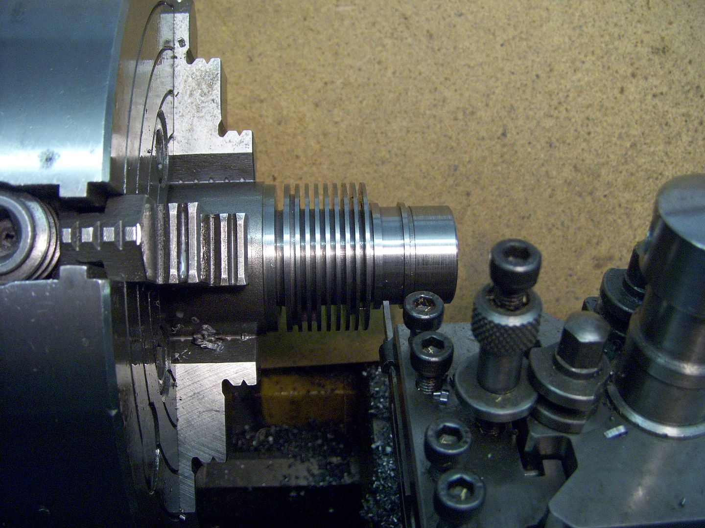
25215 forum posts 3105 photos 1 articles | Those thin parting tools don't need all the grinding that has been done to yours, just front rake ground square across. Any angle on the end will tend to push the thin blade sideways. Pack out behind the disk when setting in the chuck so you are only holding by say 3mm, packing will keep the work parallel to the chuck face. Remove packing before turning on. When you come to do the big one face off the bar, just touch with the spotting drill to mark ctr and then do all your marking out before putting back in lathe to part off, its easier to hold than a thin disc Note, if it ain't broke don't alter Similar parting tool as yours note the top and sides have not been ground and end is ground square across, cut all those grooves in steel no problem
Edited By JasonB on 12/10/2015 07:54:01 |
| Michael Gilligan | 12/10/2015 08:09:32 |
 23121 forum posts 1360 photos | Posted by Brian John on 12/10/2015 07:10:16:
2. What is the best way to salvage the two discs I have already cut ie. how to grind/polish one side down so that it is flat ? They are too thin to hold in the lathe chuck....or is there a trick to doing that ? (I could use a mandrel to remove most of the metal except for the part under the nut and later grind this bit off with a dremel tool.) . Spend a few minutes learning about 'Wax Chuck' technique, as used by watchmakers. ... Originally [and best] done with Shellac; but 'SuperGlue' is a reasonable alternative for jobs like this. MichaelG. |
| Hopper | 12/10/2015 08:09:57 |
 7881 forum posts 397 photos | It may be that the parting tool was not set dead square to the lathe axis. If I want precision parting i will sometimes check the alignment of the parting tool with a dial indicator to make sure it is dead on. Ian SC is right about using stainless rather than aluminium for the displacer cylinder. The cylinder needs to conduct as little heat as possible, so that there is a considerable difference in temperature between the hot end with the candle on it and the cool end with the fins on it. This temperature differential is what causes the pressure differential that makes the engine work. Ally will quickly transfer the candle's heat to the cool end of the cylinder and warm it up, resulting in no-go. Stainless is a poor conductor of heat so is a pretty standard material for the displacer cylinder on Stirlings. Glass is even better. As there is a small gap between the displacer piston and the glass cylinder, you can dome the end of the displacer piston with a file in the lathe, using a shop-made radius gauge cut from a piece of cardboard or plastic as a guide. To flatten out those crank blanks, use the reverse jaws in your lathe to hold them, with a stack of washers or similar in behind them to space them out beyond the jaws but running true on the back face of the job. Then just face the crank blank off with a facing tool. (LH turning tool) Yes, drilling holes to get the radius on the profile of the crank is a good idea. I would then cut with mini hacksaw and finish with a file. So needs to be marked out first. Either by blueing and scribing in the traditional manner, or by making a full size photocopy of your drawing and cutting out the shape of the crank and gluing it to the piece of brass as a guide. That is the easy way. To do it the traditional way, use a Texta pen to blue the brass. Then set the round piece in the lathe chuck and use a pointed tool bit to scribe a centre line across the diameter and then another at 90 degrees to that line. Centre pop the cross int he middle and this is the reference point for layout. You could also scribe the two lines for the throw of the crank by raising or lowering the height of the tool used to scribe the first centre line and scribing two lines to define the straight edge of the crank. To mark up the two lines at 120 degrees for the angled faces of the counterweights on the crank, you can again use the lathe to markout. Your three jaw chuck can easily be used to mark out as each of the 3 jaws is 120 degrees from the next. So setting one jaw dead vertical, then rotating the next jaw to the same position give you your 120 degrees and you can use the lathe tool tip to scribe the line again. Kind of hard to explain in words but hopefully you get my drift.
|
| Howi | 12/10/2015 09:07:41 |
442 forum posts 19 photos | Changing plans is OK if the person making the changes is more experienced than the original designer. I would imagine you will want the engine to work after you have finished it, so would suggest make as per plan, get it running, THEN make your changes and see what differences your changes make. I doubt whether you will better the original, please feel free to prove me wrong. Howard |
| JasonB | 12/10/2015 09:16:00 |
25215 forum posts 3105 photos 1 articles | There is also the question of whether the machine is upto boring a stainless steel cylinder that long. If you are only changing the glass to avoid rounding the end of the displacer that would be easier than boring the hole. While I'm on what sort of drill do you have, can't remember if its handheld or a bench drill? Edited By JasonB on 12/10/2015 09:16:37 |
| Ian S C | 12/10/2015 12:09:17 |
7468 forum posts 230 photos | I would suggest that instead of making the hot cap from solid, try and get some tube, I'v been getting a stainless disc TIG welded in the end of mine, but my tame TIGer was having eye sight problems last time, so the next one will be brazed in, I use either a narrow strip, or piece of brass wire, It's cheap, and stands the heat on the displacer. The hot cap on my motors needs to withstand red heat. The hot cap for my first tthree Ian S C
|


 (2).jpg")


Please login to post a reply.
Magazine Locator
Want the latest issue of Model Engineer or Model Engineers' Workshop? Use our magazine locator links to find your nearest stockist!
Sign up to our Newsletter
Sign up to our newsletter and get a free digital issue.
You can unsubscribe at anytime. View our privacy policy at www.mortons.co.uk/privacy
Latest Forum Posts
- *Oct 2023: FORUM MIGRATION TIMELINE*
05/10/2023 07:57:11 - Making ER11 collet chuck
05/10/2023 07:56:24 - What did you do today? 2023
05/10/2023 07:25:01 - Orrery
05/10/2023 06:00:41 - Wera hand-tools
05/10/2023 05:47:07 - New member
05/10/2023 04:40:11 - Problems with external pot on at1 vfd
05/10/2023 00:06:32 - Drain plug
04/10/2023 23:36:17 - digi phase converter for 10 machines.....
04/10/2023 23:13:48 - Winter Storage Of Locomotives
04/10/2023 21:02:11 - More Latest Posts...
- View All Topics
Support Our Partners


Shopping Partners
Subscription Offer

Latest "For Sale" Ads
- Reeves** - Rebuilt Royal Scot by Martin Evans
by John Broughton
£300.00 - BRITANNIA 5" GAUGE James Perrier
by Jon Seabright 1
£2,500.00 - Drill Grinder - for restoration
by Nigel Graham 2
£0.00 - WARCO WM18 MILLING MACHINE
by Alex Chudley
£1,200.00 - MYFORD SUPER 7 LATHE
by Alex Chudley
£2,000.00 - More "For Sale" Ads...
Latest "Wanted" Ads
- D1-3 backplate
by Michael Horley
Price Not Specified - fixed steady for a Colchester bantam mark1 800
by George Jervis
Price Not Specified - lbsc pansy
by JACK SIDEBOTHAM
Price Not Specified - Pratt Burnerd multifit chuck key.
by Tim Riome
Price Not Specified - BANDSAW BLADE WELDER
by HUGH
Price Not Specified - More "Wanted" Ads...
Get In Touch!
Do you want to contact the Model Engineer and Model Engineers' Workshop team?
You can contact us by phone, mail or email about the magazines including becoming a contributor, submitting reader's letters or making queries about articles. You can also get in touch about this website, advertising or other general issues.
Click THIS LINK for full contact details.
For subscription issues please see THIS LINK.
Digital Back Issues


Donate

 Register
 Log-in
Model Engineer Magazine
- Percival Marshall
- M.E. History
- LittleLEC
- M.E. Clock

ME Workshop
- An Adcock
- & Shipley
- Horizontal
- Mill

Subscribe Now
- Great savings
- Delivered to your door

Pre-order your copy!
- Delivered to your doorstep!
- Free UK delivery!
All Forum Topics > Stationary engines > Stirling Engine : Laura