Forum sponsored by:

Lathe design not keeping up
| John Stevenson | 23/06/2015 00:32:24 |
 5068 forum posts 3 photos | Came to the conclusion that lathe design isn't keeping up with technology and this based on medium sized lathes.
Back in my early days of older machines, HSS tools most of my work was done at about 490 revs on machines that struggled to get faster than 700 anyway.
Move on to the early carbide and newer machines and now found I was working around the 780 mark on machines that could probably do 950 revs. Fast forward to today's machines which can run at anything from 1200 to 2500 and I'm finding that my preferred speed with modern tipped tooling is around the 1200 mark.
Now you would think that this means machines have kept up which to an extent they have except for that bloody great train of mangle gears hanging off the end of the lathe usually in a glass fibre or tin box that does nothing but amplify the din.
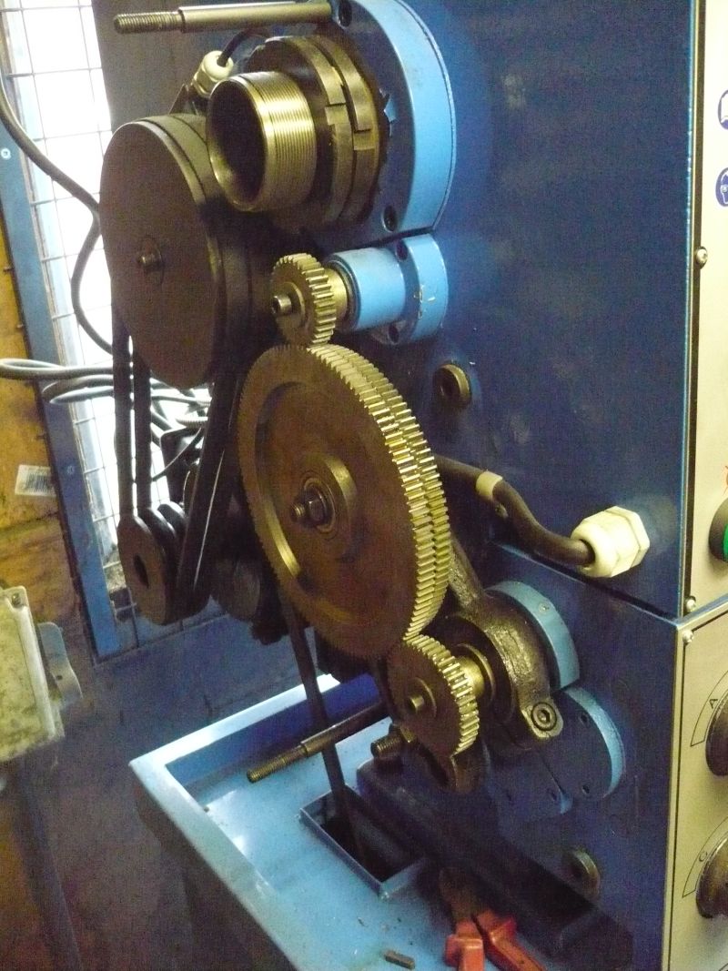
So a while ago on my TOS lathe which is the workhorse of choice a quick look at all the threading / feed options and one range stood out as having all the popular threads. This was a simple three gear drive with a central idler to span the distance.
{ [ NOTE ] Can't find the pictures of the TOS but this is a generic Chinese 14 x 36 lathe that was also done .}
Typical of many lathes out there and at 1200 revs this thing howls. The driver and driven are 33 to 44 for this common range so any 3 / 4 ratio will do.
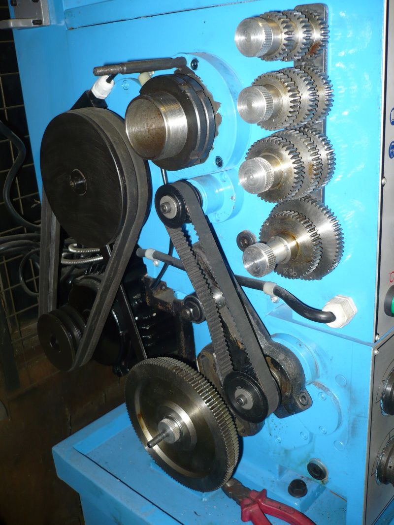
Quick look at what is available in HTD5 series timing belts and a 24 / 32 will fit the bill, so order two pulleys up and a belt and we get this.
And enough room to get a rack for the gears needed for all the specials instead of kicking about in a box.
At the moment I'm doing the same on the new Bantam with a 21 driving a 72 to replace a 4 gear compound train. Gears came today but the Bantam gears are 8 spline and not bored and keyed so setting up to make the splining as easy as possible and I'll add to this post as I go along. It is now possible on the TOS and the Chinese lathe to run as fast as possible with hardly any noise and it's smoother. Simple job to swap the pulleys for gears if you need a special pitch, it's only the same as swapping gears anyway.
More to follow later.
|
| duncan webster | 23/06/2015 00:43:24 |
| 5307 forum posts 83 photos | Just like the Colchester Chipmaster, only about 50 years ago! |
| John Stevenson | 23/06/2015 01:13:57 |
5068 forum posts 3 photos | Not saying it's new, just not in general use. The CVA and Monarch 10EE also had belt drive for fine feed but these all still used gears for threading, same as the Chipmaster. |
| Michael Gilligan | 23/06/2015 06:47:56 |
 23121 forum posts 1360 photos | John, As we have come to expect from you ... That looks a very practical improvement, and a great use of available technology. I suspect that the lathe manufacturers have [or at least choose to display] a rather conservative attitude, and they present Gears as being the 'proper' thing to use for precision screwcutting. Modern timing belts should be well up to the job; but there is still a lot of 'perception' involved in many purchasing decisions. MichaelG. |
| JasonB | 23/06/2015 07:31:10 |
 25215 forum posts 3105 photos 1 articles | Looks like a good mod, my 280 spends 99% of its time with the same gear train which gives the finest 3 feed rates, its not too bad noise wise if you get the gears set right but definately a lot nosier than if you swing the banjo out of mesh.
J |
| Howard Lewis | 23/06/2015 08:36:03 |
| 7227 forum posts 21 photos | Toothed belts provide a sufficiently reliable drive for Camshafts and Fuel Injection Pumps (which really do give the belt some stick!) so could be a good way to go. For anyone who wants to quieten their lathe, without changing to belt drives, they could try what was done to reduce noise on Diesel engines. Instead of the front pulley being solid, it was changed to spoked. This reduced the area that could transmit noise to the surroundings Since my Far Eastern lathe has a similar gear layout to that shown by John, maybe the big idler (120/127T) should be removed and have some large holes drilled/bored in it? There are times when it "rings" at higher speeds. Another alternative, which might improve finish or thread pitch consistency, would be to bolt on a lot of lead sheets. This would dampen the sound ( Sumps consisting of a sheet steel/lead/sheet steel sandwich were effective, but heavy) and provide a flywheel effect to give a drive with less instantaneous speed variation. Just a thought. Howard |
| richardandtracy | 23/06/2015 08:48:50 |
 943 forum posts 10 photos | It is a nice idea. The reason why lathe manufacturers don't do it as standard is, I think, both inertia & price. Inertia is obvious. Price, well, it's a good deal cheaper to hog out spur gears en mass than die cast or extrude timing belt pulleys. If nothing else, the raw material cost of an aluminium/white metal pulley will be more than the finished cost of a steel spur gear. Regards, Richard.
|
| Michael Gilligan | 23/06/2015 09:26:19 |
23121 forum posts 1360 photos | That's interesting, Richard You and I seem to have opposite opinions regarding the "value" of Gears. ... I don't know which of us is right, so hopefully this discussion will run for a while. MichaelG. |
| Brian Wood | 23/06/2015 10:58:43 |
| 2742 forum posts 39 photos | That's a neat modification John, the sort of thing you tend to excel at, but am I the only one to spot that feed rotation into the gearbox will now be reversed without an idler interposed in the drive? Regards Brian |
| John Stevenson | 23/06/2015 11:21:00 |
5068 forum posts 3 photos | No Brian, Gears :- Driver - clockwise Idler - anticlock Driven - clockwise
Pulleys:- Driver - clockwise Driven - clockwise
In any case you still have the tumbler / feed lever for selection. |
| Brian Wood | 23/06/2015 11:37:18 |
| 2742 forum posts 39 photos | Hello John, And of course you are right, in which case it is an even more elegant modification. I simply hadn't thought it through fully, thank you for putting that right. Brian |
| Jon | 23/06/2015 12:12:30 |
| 1001 forum posts 49 photos | Good idea carries some weight. My only concern would be the belt flex/play over solid interlocking gears. Noticed and bewildered why the copy capital of the world has never done the Harrison/Colchester method from a good 50 years ago. I don't need to change change wheels for metric or imperial and swore blind 5 years ago would never ever have another lathe had to mess about with change wheels. |
| Muzzer | 23/06/2015 12:18:14 |
 2904 forum posts 448 photos | John - you may recall I enquired about the spline dimensions for the Bantam about 18 months ago when I was making a screwcutting clutch for my Bantam. I made a splined shaft as part of the job and it fitted very nicely. If you want to sanity check your measurements, I can give you a copy of what I worked to. Nice idea certainly. It's possible to disengage the geartrain by leaving the direction selector in mid position but like you, I try to use indexable tooling where possible and this pretty much requires power feed. As you say, it's a noisy business. The only time I've needed specific gears is for cutting threads and I've always changed back to "feed" ratios afterwards. I'd be up for a set of splined toothed gears if you have the option to acquire or make any extra sets. Murray |
| Tony Ray | 23/06/2015 12:42:33 |
| 238 forum posts 47 photos | John, I agree, is it because most widgets are now made on CNC machines? A great halfway house would seem to be the electronic leadscrew - by electonically controlling the speed of the LS relative to the mandrel any pitch can be cut but AFAIK its not commerically available on new machines. In a similar vein I wonder why the linear scales for DRO's aren't simply incorporated into the slideways rather than leaving the user to have to retro fit them (quite often inelegantly due to space contraints). Tony
|
| Bazyle | 23/06/2015 13:31:06 |
 6956 forum posts 229 photos | You obviously have a good SCGB on the TOS, and the Colchester/Harrison must be well selected too. When you look at a lot of the new medium to small hobbyist lathes with 3 or 4 knob SCGB they look like they must be versatile. |
| John Stevenson | 23/06/2015 13:49:09 |
5068 forum posts 3 photos | The TOS and the Chinese lathe are both metric and hence with one set of gears all the common metrics are in this one range so worth doing. However on both the TOS and the Chinese lathe when you go into imperial to get what i call a full range you have three different gear setups to contend with.
As most of my work is predominantly metric then this suits me. The Bantam is a full imperial machine but even this has two ranges 3 to 14 tpi and 14 to 80 tpi. I am cloning the 14 to 80 tpi range as this will have more of the common threads I use and obviously a finer feed.
I know may machines will do full imperial and metric in the same box but when new these would be more expensive machines. One only gets what one pays for.
It's not a be all and end all mod but like Jason it will probably cover 90% of the work and in the lower range of gears because of the high ratio it is very noisy at speed, the fibre glass end cover doesn't help at all.
Tony mentions the electronic leadscrew but long short is none of the low end versions works accurately. By the time you move upmarket enough to get something with decent multi line encoders you are paying for it. Then the rub is you have to manually retract the tool at the end and send it back, so fit a stepper or servo on to do this job and hey boys we have invented a 2 axis CNC lathe !!
Murray, I just copied the spline detail out of an existing gear and it fits OK. I only need one splined gear for the large 72 on the gearbox end. The smaller top 21 t pulley should be splined to fit on the shear pin drive but it's easier to build this drive into the pulley.
I have no plans to produce any gears other than a couple of special but I have some spare gears that can act as donor splines. |
| Pete | 23/06/2015 23:01:44 |
| 128 forum posts | Well I'd sure have to agree that the current lathe designs at the lower to mid range end of the manual machine market aren't or haven't changed much at all in the last 50 years. I do suspect that's about to change, or at least I hope it will, and fairly soon though. Volume production of at least semi CNC machine's shouldn't be much or maybe any more expensive than what it takes to build and add a Norton style gearbox and the two axis power feeds. Add a built in DRO like Tony has already mentioned, and then tie it's positional feedback into the CNC for a very accurate location of the tool tip. So you could then use fairly inaccurate and therefore much cheaper ball screws and nuts. Even any future wear on the screws and nut's should be able to be accurately compensated for. Just let the CNC map the steps against the actual slide movements that the DRO is measuring. Tormach brought out a pretty simple and fairly cheap semi automated CNC surface grinder last year? Instead of needing a heavy weight, noisy, and quite expensive hydraulic system to give you the really useful reciprocating table drive and user pre selected automatic step overs in the Y axis, it's set up as a simple but limited CNC with an easily programmable system to input your parameters for what you want for table speeds, distance, and feeds. As far as I know the Z axis is still fully manual, but that should be just fine with those smaller surface grinders. Use the same idea with a 2 axis semi CNC drive and a GOOD and ACCURATE rotary encoder on the spindle with a really well designed and rigid lathe and there's your screw cutting system. Plus with almost zero extra money you could have the constant surface speed (CSS) for facing larger diameters that's already available on a few higher end manual lathes that have the Newall CSS feature on some of there DRO's. Exactly why we don't yet have this yet? Probably because were just not demanding it in large enough numbers yet that one of the larger dealers such as Grizzly is willing to take a chance and requested one of the better factory's to start working on a new design of this type, and in a variety of sizes. With what it's capability's would be, then there's not many manual machine users that wouldn't want something exactly like this as long as the prices could be kept in check. Make the inputs user friendly, fast, and dead simple, and then even the smaller one off jobber shops just like John's would be wanting one. It's even not really much past today's more usual lathes that comes with 2 axis power feeds. Pete |
| John Stevenson | 24/06/2015 00:03:27 |
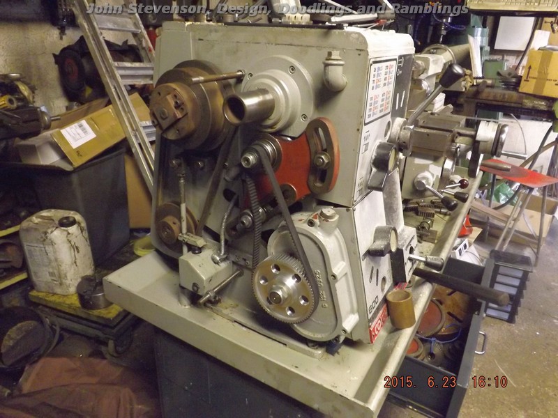
5068 forum posts 3 photos | OK, bit further along with this. First off this is what it looks like in the high ratio for screw cutting.
Simple three gear drive and all the gears on this lathe are 8 shallow splines and special to Colchester.
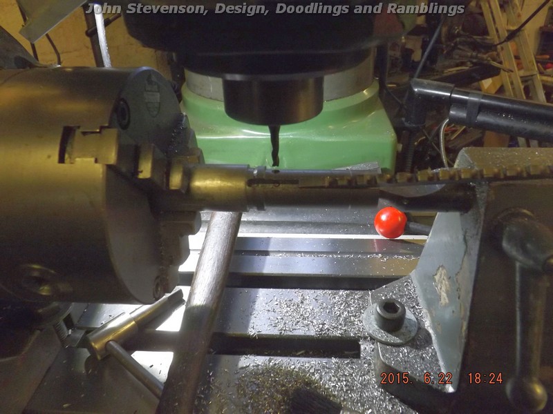
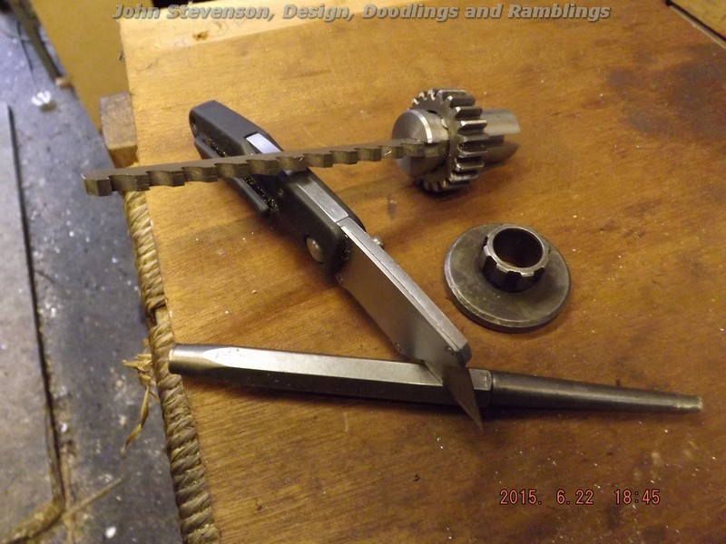
The spline is 4.36mm wide measured on one of the gears and that's not a standard size in imperial or metric but a while ago I bought a job lot of broaches and bushes and in this was a broken 8mm broach missing about the top 1/3rd. So bang it on the surface grinder and take both sides down so I finish up with a parallel broach at 4.36mm wide. Broaches do not have side relief, only front clearance that that works out well.
Next job is to make a new bush with the OD to fit a gear's ID and a 4.37mm slot in it for the broach. Whilst this is set up in the dividing head on the mill, the bank is rotated 1/8th of a turn or 45 degrees and a hole plunged in with the 4mm cutter.
Then a small top hatted pin id pressed into the hole with the top hat 4.36mm in diameter.
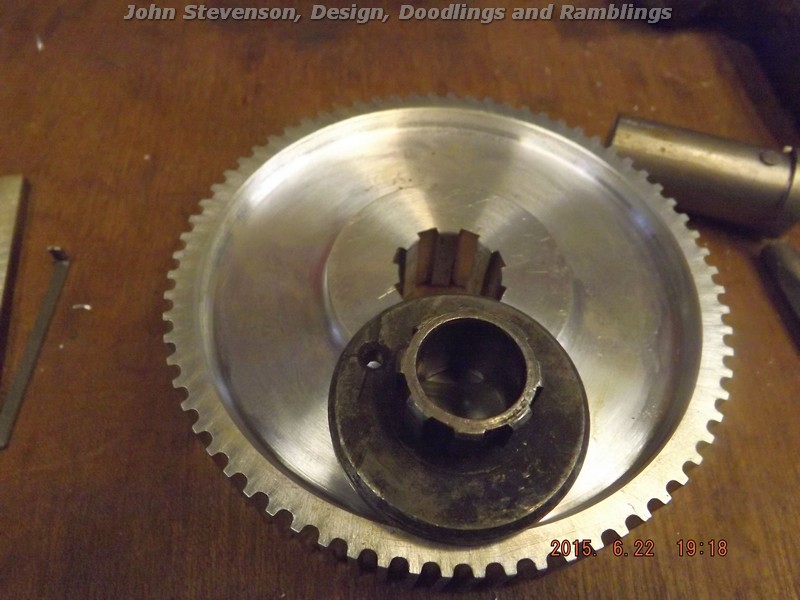
Close up of the bits. The idea is you broach one slot, turn the bush so the pin fits into the previous slot and do the second. Wrinse and repeat untill all 8 are done and with a bit of luck and fair wind you get this.
The bit on the top is the top drive that carries a shear pin and this one is a spare I have and is pressed into service as a gauge.
So that sorts the bottom bit out.
Top pulley is splined identical and fits onto the splined shear top hat but to save all this messing I propost to fit the shear drive direct to the pulley.
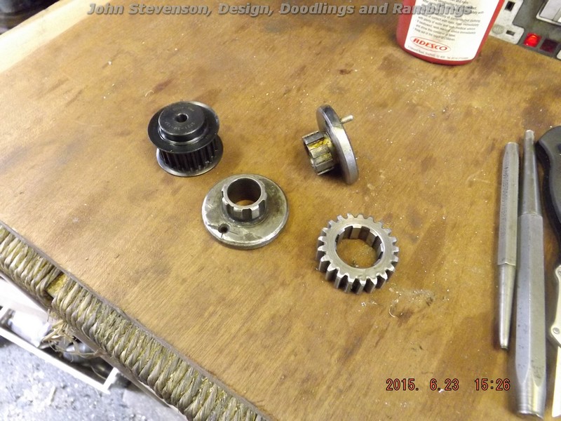
Blank pulley, shear drive off the machine, spare shear drive and a gear.
Idea is to transpose a new plate onto the pulley boss, drill for a shear pin and bore and ream 5/8" like the original which was done but I forgot to get a picture of it.
So later on today we finish up with this. Pulleys done, belt fitted and a jockey made up of 3 spare sealed bearings to take the tension up.
Tested this at 1600 rpm which is as fast as this one goes and there is no noticeable difference in noise with the drive engaged or not.
So very well pleased with this and this drive is a clone of the finer ratios and not the one in the original picture. The original has been replaced as tomorrow I have to thread some imperial threads onto metric shaft sizes for a Wadkin bandsaw at 7 tpi and 14 tpi then the belt drive will be re-fitted and hopefully stay on for a long while. |
| jim' | 24/06/2015 05:14:57 |
| 72 forum posts 6 photos | Very interesting.
Just one question. How does the jockey/tension wheel cope in "reverse"?
Thanks
Jim |
| Neil Wyatt | 24/06/2015 09:33:47 |
 19226 forum posts 749 photos 86 articles | There's no tumbler reverse before the belt so it's not an issue, I guess.You'd have to add an idler after the belt for a left hand thread, in which case the belt would still run the same way. Neil |
Please login to post a reply.
Magazine Locator
Want the latest issue of Model Engineer or Model Engineers' Workshop? Use our magazine locator links to find your nearest stockist!
Sign up to our Newsletter
Sign up to our newsletter and get a free digital issue.
You can unsubscribe at anytime. View our privacy policy at www.mortons.co.uk/privacy
Latest Forum Posts
- *Oct 2023: FORUM MIGRATION TIMELINE*
05/10/2023 07:57:11 - Making ER11 collet chuck
05/10/2023 07:56:24 - What did you do today? 2023
05/10/2023 07:25:01 - Orrery
05/10/2023 06:00:41 - Wera hand-tools
05/10/2023 05:47:07 - New member
05/10/2023 04:40:11 - Problems with external pot on at1 vfd
05/10/2023 00:06:32 - Drain plug
04/10/2023 23:36:17 - digi phase converter for 10 machines.....
04/10/2023 23:13:48 - Winter Storage Of Locomotives
04/10/2023 21:02:11 - More Latest Posts...
- View All Topics
Support Our Partners


Shopping Partners
Subscription Offer

Latest "For Sale" Ads
- Reeves** - Rebuilt Royal Scot by Martin Evans
by John Broughton
£300.00 - BRITANNIA 5" GAUGE James Perrier
by Jon Seabright 1
£2,500.00 - Drill Grinder - for restoration
by Nigel Graham 2
£0.00 - WARCO WM18 MILLING MACHINE
by Alex Chudley
£1,200.00 - MYFORD SUPER 7 LATHE
by Alex Chudley
£2,000.00 - More "For Sale" Ads...
Latest "Wanted" Ads
- D1-3 backplate
by Michael Horley
Price Not Specified - fixed steady for a Colchester bantam mark1 800
by George Jervis
Price Not Specified - lbsc pansy
by JACK SIDEBOTHAM
Price Not Specified - Pratt Burnerd multifit chuck key.
by Tim Riome
Price Not Specified - BANDSAW BLADE WELDER
by HUGH
Price Not Specified - More "Wanted" Ads...
Get In Touch!
Do you want to contact the Model Engineer and Model Engineers' Workshop team?
You can contact us by phone, mail or email about the magazines including becoming a contributor, submitting reader's letters or making queries about articles. You can also get in touch about this website, advertising or other general issues.
Click THIS LINK for full contact details.
For subscription issues please see THIS LINK.
Digital Back Issues


Donate

 Register
 Log-in
Model Engineer Magazine
- Percival Marshall
- M.E. History
- LittleLEC
- M.E. Clock

ME Workshop
- An Adcock
- & Shipley
- Horizontal
- Mill

Subscribe Now
- Great savings
- Delivered to your door

Pre-order your copy!
- Delivered to your doorstep!
- Free UK delivery!
All Forum Topics > Manual machine tools > Lathe design not keeping up