Forum sponsored by:

WARCO WM-250 lathe family and WM16 mill - 001
........advice and support for owners.
| Thor 🇳🇴 | 10/08/2013 17:32:00 |
 1766 forum posts 46 photos | Hi Rik, I agree 75mm dia. rotary table is a bit small. I have a 100mm dia. and often find that too small, so I made a slightly larger one (120mm) after Dean's description. You could make your own in a size that suits you. As long as the rotary table is flat on the milling table your mill should handle a 150mm rotary table. Thor |
| JasonB | 10/08/2013 20:53:14 |
 25215 forum posts 3105 photos 1 articles |
Posted by Rik Shaw on 10/08/2013 16:25:33:
Size wise, WARCO will not recommend a rotary table any larger than an HV4 on my WM16 mill which at just 75mm dia. is trifling.
The HV4 is 110mm dia not 75mm |
| Mark P. | 11/08/2013 11:53:18 |
 634 forum posts 9 photos | I made an adaptor for my rotary table to take the faceplate from my WM250. Mark P. |
| Crocadillopig | 11/08/2013 14:33:18 |
| 30 forum posts 4 photos | I use a 9" 'T slotted' faceplate from RDG (ref 210989) with a shortened adapter (ref 823AD Chuck) which incorporates a 2 morse taper although other locators are available. This fits my 4" vertex rotary table (ref 324958). This set up works for me on my WM16, although restricted in 'Y' axis, travel is still useable in 'X' and 'Z'. If you find it is not rigid enough for heftier cuts, support the overhang with a screw jack although I have never found the need Russ |
| mechman48 | 25/08/2013 16:16:49 |
 2947 forum posts 468 photos | Hi all To keep this thread going I have written a little description of checking the accuracy of my WM250V-F chuck under the thread titled .. Chuck accuracy 25/08/2013... as it fitted the context, & it also applies under this thread as it is on the Warco family... can't let this thread lose track for lack of coments..have tried to link to it but can't seem to do it... any assistance? George Edited By JasonB on 25/08/2013 16:22:14 |
| Thor 🇳🇴 | 25/08/2013 16:41:31 |
1766 forum posts 46 photos | Hi George, I have checked out your link. Thor Edited By Thor on 25/08/2013 16:42:53 |
| mechman48 | 25/08/2013 16:42:26 |
2947 forum posts 468 photos |
JasonB Thanks for linking it .. how did you do it? G |
| mechman48 | 25/08/2013 16:48:06 |
2947 forum posts 468 photos | Thor Yes, thanks.. same question as to Jason.. How? |
| JasonB | 25/08/2013 16:52:59 |
25215 forum posts 3105 photos 1 articles | View the Chuck thread, copy (right click, then copy) the URL from the top left of the browser. Or from the latest posts right click the chuck thread and select copy shortcut to get the url Type your post here, highlight the text you want the link to be then click the icon with the globe & chain link, paste the url into the box in the window that comes up and bobs your uncle. |
| Thor 🇳🇴 | 25/08/2013 16:57:15 |
1766 forum posts 46 photos | Hi George, Open two tabs in your browser, both pointing to this forum. Open the Chuck Accuracy in one tab, this one in another. In the Chuck Accuracy tab you click in the address line with the mouse pointer and then press Ctrl A on the keyboard to mark all, and then press Ctrl C on the keyboard to copy this address. In the edit box mark a word with the mouse, then there is a globe with a chain above the editor, click that and it opens up a box which asks for the URL. Click in that with the mouse pointer and then Ctrl V. Click the Ok button. Thor Jason types faster than me. Edited By Thor on 25/08/2013 16:57:45 Edited By Thor on 25/08/2013 17:08:31 |
| JasonB | 25/08/2013 17:11:39 |
25215 forum posts 3105 photos 1 articles | Posted by Thor on 25/08/2013 16:57:15:
Jason types faster than me. Thats because he just uses the mouse, none of that jumping back and forth between mouse and keyboard to press Ctrl *. |
| Rik Shaw | 25/08/2013 17:50:10 |
 1494 forum posts 403 photos | I want to buy a rear mounted tool post for my WM250V-F lathe which I would like to use with a parting off tool. As far as I can see WARCO do not list one as an extra. Do you know where I can buy one? Rik |
| mechman48 | 25/08/2013 23:02:39 |
2947 forum posts 468 photos | JasonB/Thor... thanks for the tip. Rick... I made mine from a Hemmingway kit as I couldn't find one to buy either (non available for this machine) but had to modify fixing from that described in kit plans & the blade angle left too much sticking out to meet centre height causing blade to flex (not rigid enough) & parted off pieces to have concave /convex sides so have used ordinary parting off holder inverted in 12 mm slot on other side of block ... lot more rigidity... works a treat now. Will post pic of alternative holder set up... when I find it ! other pics in album 'Rear tool post', will do write up on process later but pics will give you good insight.
Cheers George |
| mechman48 | 26/08/2013 17:20:20 |
2947 forum posts 468 photos | Rick For your info... from Hemmingway kits, this is what I bought... Rear Tool Post for Larger Lathes Ref: HK 1071 Price: £49.30 (Including VAT at 20%) One of George Thomas' simplest and most elegant designs, the Rear Tool Post, with its indexing turret, has become a vital addition to all Myford lathes for the past 30 years. And now, Hemingway is pleased to announce a new version, based on the work of both G H Thomas and E Riley. Suitable for lathes with up to 3 ½" between the cross slide and centre, the kit includes the main casting and all material to complete a substantial Rear Tool Post for your Boxford, South Bend, Atlas, Chester, Harrison, Myford 254, Colchester, Warco, Grizzly. Plus many more. The Rear Tool Post is designed to engage with either a single T slot or a pair of tapped holes towards the rear of your cross slide. The turret is designed to accept a parting blade and an additional inverted tool up to ½" square. Picture shows the tool post armed with an inverted carbide insert holder and HSS chamfering tool.
Cheers George
|
| cliff leach | 27/08/2013 12:05:07 |
 7 forum posts | Hi, I have a WM16 mill and a WM180 lathe. On the mill I wanted DROs for the X and Y Axis (it comes with a Quill - Z Axis DRO). I also wanted Y axis stops (it comes with X axis stops) After a lot of thought and desinging I came up with a solution to this and I must admit that using DROs makes life much easier and improves precision. I used DROs with remote readouts from ARC and machined up the brackets from scrap stock and old parts from defunct computer pritners. I am now working on an electrical actuator for the Z axis (main column) with up and down feed, not as part of a CNC project (that will come later) but just using a regular DC motor to move the column up and down since I find it hard to reach the top of the mill since I am a wheelchair user. I am submitting the work as an article to the magazine, but if anyone out there wants details, then just Private mesage me. Edited By JasonB on 27/08/2013 15:46:00 |
| Rik Shaw | 17/09/2013 10:51:59 |
1494 forum posts 403 photos | Have not used my new WM 250V-F very much yet but yesterday after cleaning and lubricating the bed I wound the apron back and forth by hand to spread the oil and noticed that the internal mechanism was not as free as it had been. After scratching my head a while I checked the sight glass on the apron but I could not see an oil level line. Either it was over full or............... Removed filler plug and started to fill with oil.It took a fair bit of oil to get the level showing in the sight glass. I can only assume the lathe was shipped without oil in the apron, would you believe it?. The headstock is OK and shows the correct level. Rik |
| JasonB | 17/09/2013 11:21:56 |
25215 forum posts 3105 photos 1 articles | Are you sure its not all leaked out into the tray |
| Michael Gilligan | 17/09/2013 11:31:06 |
 23121 forum posts 1360 photos | Posted by Rik Shaw on 17/09/2013 10:51:59:
... would you believe it?. Rik . In a word ... Yes. Thinks; it might be worth checking what is in there. MichaelG. |
| mechman48 | 17/09/2013 13:10:17 |
2947 forum posts 468 photos | Rick, I have the same problem; when I clean mine down I noticed a film of oil in the tray & closer inspection reveals that there is a weep of oil clinging to the bottom of the saddle, I have checked all fastenings for tightness & all ok, I came to the conclusion that the oil is coming from either the sight glass (Manual part # 30), but there again it would stop once the level reached the below the sight glass, or possibly the screw (part # 27) which I cannot see with the limited view I get between the apron /saddle & tray, nor feel any joint in that location, probably the manufacturer has covered the joint in the process of enamelling the saddle. If you look in the manual there is also an item that is not identified (in mine)...Lathe Apron assembly page... in between parts 27/28/29/30, it looks to me like a cap, spring, & ball bearing on the diagram but not identified? so there is another possible route for oil to escape. Considering the general assembly of these machines it also wouldn't surprise me if the label screw holes have been drilled right through into the saddle & allowing oil to seep past the screws....... Just been to check on mine & it is this unidentified screw where my leak is, it is a socket gubscrew (used an inspection mirror) but as to its purpose?, I can only surmise from the layout diagram it is the retaining pin assembly for the half nut operating cam shaft (part # 32). Having topped up the level earlier on this year,its still showing 3/4 level, & not wanting to dismantle the saddle at this point, its liveable so its a case of checking the level each week, so I suggest this is your first port of call to remedy Just a few ideas to ponder. Cheers George |
| mechman48 | 17/09/2013 16:13:06 |
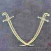
2947 forum posts 468 photos | Rik/all Have been pottering in the garage ... again, & double checked the saddle re oil leak (above post), & what I've deduced, by feel, is that... 1). Operating the half nut lever the unidentified item is the spring loaded detent assembly for the half nut cam... #32 (manual shows it as having a hole in the shaft but must be a dimple) ... as can definitely feel spring & ball action... 2) The other part (#27) is actually the drain plug, identified as 'Screw'... 3) There is a leak from where the half nut lever comes out of the saddle & locates into the 'Handle knob'.. Part # 67.oil is weeping from there down the front of the saddle & hence running under the saddle ending up in the tray. So I would consider the 3 primary leak points as:
Plus, as an outside point…
You can see the spring detent grub screw in the top of the mirror & the drain plug at the bottom, another leak was, as mentioned, coming from the lever bottom position, top right of pic where the paint has been chipped.
So that’s my two ‘pennorth, hope it helps. Cheers George Edited By mechman48 on 17/09/2013 16:14:44 |


Please login to post a reply.
Magazine Locator
Want the latest issue of Model Engineer or Model Engineers' Workshop? Use our magazine locator links to find your nearest stockist!
Sign up to our Newsletter
Sign up to our newsletter and get a free digital issue.
You can unsubscribe at anytime. View our privacy policy at www.mortons.co.uk/privacy
Latest Forum Posts
- *Oct 2023: FORUM MIGRATION TIMELINE*
05/10/2023 07:57:11 - Making ER11 collet chuck
05/10/2023 07:56:24 - What did you do today? 2023
05/10/2023 07:25:01 - Orrery
05/10/2023 06:00:41 - Wera hand-tools
05/10/2023 05:47:07 - New member
05/10/2023 04:40:11 - Problems with external pot on at1 vfd
05/10/2023 00:06:32 - Drain plug
04/10/2023 23:36:17 - digi phase converter for 10 machines.....
04/10/2023 23:13:48 - Winter Storage Of Locomotives
04/10/2023 21:02:11 - More Latest Posts...
- View All Topics
Support Our Partners


Shopping Partners
Subscription Offer

Latest "For Sale" Ads
- Reeves** - Rebuilt Royal Scot by Martin Evans
by John Broughton
£300.00 - BRITANNIA 5" GAUGE James Perrier
by Jon Seabright 1
£2,500.00 - Drill Grinder - for restoration
by Nigel Graham 2
£0.00 - WARCO WM18 MILLING MACHINE
by Alex Chudley
£1,200.00 - MYFORD SUPER 7 LATHE
by Alex Chudley
£2,000.00 - More "For Sale" Ads...
Latest "Wanted" Ads
- D1-3 backplate
by Michael Horley
Price Not Specified - fixed steady for a Colchester bantam mark1 800
by George Jervis
Price Not Specified - lbsc pansy
by JACK SIDEBOTHAM
Price Not Specified - Pratt Burnerd multifit chuck key.
by Tim Riome
Price Not Specified - BANDSAW BLADE WELDER
by HUGH
Price Not Specified - More "Wanted" Ads...
Get In Touch!
Do you want to contact the Model Engineer and Model Engineers' Workshop team?
You can contact us by phone, mail or email about the magazines including becoming a contributor, submitting reader's letters or making queries about articles. You can also get in touch about this website, advertising or other general issues.
Click THIS LINK for full contact details.
For subscription issues please see THIS LINK.
Digital Back Issues


Donate

 Register
 Log-in
Model Engineer Magazine
- Percival Marshall
- M.E. History
- LittleLEC
- M.E. Clock

ME Workshop
- An Adcock
- & Shipley
- Horizontal
- Mill

Subscribe Now
- Great savings
- Delivered to your door

Pre-order your copy!
- Delivered to your doorstep!
- Free UK delivery!
All Forum Topics > Workshop Tools and Tooling > WARCO WM-250 lathe family and WM16 mill - 001