Forum sponsored by:

The Workshop Progress Thread 2019
| JasonB | 19/08/2019 07:25:15 |
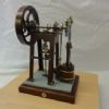
 25215 forum posts 3105 photos 1 articles | Thank's Ron, I think it was that video that first got me thinking of making the engine so I got the 1938 Practical Mechanics Shop notes that had both of the two part article in them. One shows the patterns to make your own castings and the other the construction. I have scaled it down from 1 1/4" bore to 24mm and altered just about every part in some way but still kept to the basic layout and overall look. As you noted the simple rockers and bent wire pushrods are a bit basic so I have some shapely rockers ( see the KX£ adventure thread) with screw adjusters and the tappets ride in bronze bearings. I will deviate a bit on the carb which is just a plain venturi type on the original by adding a throttle and doing something a bit nicer than the metal pot seen in the video for the fuel tank. As the engine is just for show being able to blip the throttle will be more enjoyable than having it just running flat out and also save it getting too hot while stationary.
Although several illustrations show the engine in a boat hull this one is an interesting use for it and if Michael G. is looking in he will approve of the tool being used. Also shows the basic rocker and rod design.
Edited By JasonB on 19/08/2019 07:35:56 |
| Ron Laden | 19/08/2019 07:57:27 |
 2320 forum posts 452 photos | Good stuff Jason, those adjustable rockers look far better than the plain flat type. I was going to ask about the carb, when watching the video I was waiting for the throttle to be blipped but as you say it is just runs at a fixed speed. A carb with a throttle will be a good upgrade I think. |
| Michael Gilligan | 19/08/2019 08:54:37 |
 23121 forum posts 1360 photos | Posted by JasonB on 19/08/2019 07:25:15:
Although several illustrations show the engine in a boat hull this one is an interesting use for it and if Michael G. is looking in he will approve of the tool being used.
. What an amazing illustration that is !! MichaelG. |
| Ron Laden | 19/08/2019 10:46:45 |
2320 forum posts 452 photos | Posted by JasonB on 19/08/2019 07:25:15:
Thank's Ron, I think it was that video that first got me thinking of making the engine so I got the 1938 Practical Mechanics Shop notes that had both of the two part article in them. One shows the patterns to make your own castings and the other the construction. I have scaled it down from 1 1/4" bore to 24mm and altered just about every part in some way but still kept to the basic layout and overall look. As you noted the simple rockers and bent wire pushrods are a bit basic so I have some shapely rockers ( see the KX£ adventure thread) with screw adjusters and the tappets ride in bronze bearings. I will deviate a bit on the carb which is just a plain venturi type on the original by adding a throttle and doing something a bit nicer than the metal pot seen in the video for the fuel tank. As the engine is just for show being able to blip the throttle will be more enjoyable than having it just running flat out and also save it getting too hot while stationary.
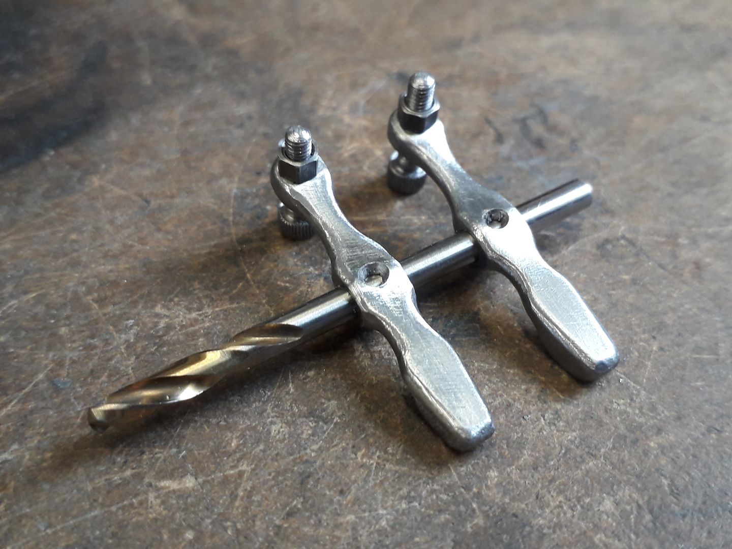
Jason, would I be correct in thinking that the bottom of the rocker adjusters are cup shaped and the push rods will be ball ended to fit inside..? |
| JasonB | 19/08/2019 12:20:01 |
25215 forum posts 3105 photos 1 articles | That's Right Ron, some models tend to use upturned cap heads screws but I put a fine straight knurl on some 4mm steel and then reduced turned the end down for a M2.5 thread before using a 3mm ball mm nose cutter to make the recess. I'll be making all my own period fixings, the cap heads are just easy during construction. The reason these engines did not have a throttle was they often went into tether boats where you had no control of the engine just dropped the boat into the water running and timed it to see how fast it could complete a set number of loops, at this sort of period they were getting around 50mph out of the top ones. Michael, the whole of the old magazines make interesting reading as they cover many subject and the adverts are as interesting or more so than the articles. Page 626 of the 1936 edition has the article about making the castings. The fuel tank turned up today along with some spares so that jamjar Maytag engine could be a possibility. I'm sure the postie must think I'm getting into jam making as I also bought some 8oz Mason jars for another engines vapour tank.
|
| Jim Nic | 28/08/2019 14:04:00 |
 406 forum posts 235 photos | At long last I have completed Stew Hart’s Overcrank engine. I knew when I started that it was a step up from anything I’d done before but thanks to Stew’s excellent drawings (which I believe were not originally drawn with publication in mind) and a bit of thought and common model engineering sense the result is shown below.
And a vid: It has taken the best part of a year but I’m pleased with it. Thanks to Stew for the drawings. Jim |
| JasonB | 28/08/2019 16:00:06 |
25215 forum posts 3105 photos 1 articles | That has turned out very well, nice slow runner too. |
| mechman48 | 28/08/2019 20:43:18 |
 2947 forum posts 468 photos | Another fine model Jim, nice runner too . George. |
| Mogens Kilde | 28/08/2019 20:50:16 |
| 60 forum posts 25 photos | A very nice engine - absolutely great job Thank you for sharing ! |
| Neil Wyatt | 29/08/2019 10:58:52 |
 19226 forum posts 749 photos 86 articles | Lovely model Jim, congrats to you and well done to Stew for the original design! Neil |
| geoff walker 1 | 29/08/2019 11:54:51 |
| 521 forum posts 217 photos | Hi Jim Lovely job mate, there's a lot going on with that engine, and only a year to make. I wouldn't be halfway there Well done Geoff |
| Jim Nic | 30/08/2019 14:42:41 |
406 forum posts 235 photos | Thanks for the kind comments gents. A little bit of a mod to do on my Grasshopper Beam engine pipework then its on to the next project - a Muncaster designed Double Acting Oscillator using the cylinder casting kindly given to me by Geoff Walker. This engine will present me with its own challenges as I am not good with castings having only used them on a Stuart Models 10V and my Grasshopper Beam (which did not turn out well with several of the castings being discarded after my attempts on them!). I have the barstock materials on order, the cylinder casting and some drawings so I'm committed now. Jim |
| John Hinkley | 31/08/2019 11:43:09 |
 1545 forum posts 484 photos | Not really workshop progress, but progress nevertheless, albeit with the continuing saga of my gearbox design. I had all but completed the internals, when I found that I'd messed up the gearchange mechanism, such that I'd ended up with the 4th and 5th gear gate in the middle! After a bit of head-scratching (and not a little profanity), I got it sorted with a bit of a re-design of the two offending selector forks and their associated rods. The "finished" design is illustrated below :
Anticipating starting to cut metal soon, I've emailed Abbey Castings to ascertain whether they can cast the selector forks in bronze for me, in a "raw" state, ready for me to machine to finished size, but have yet to receive a reply. Perhaps they are on holiday? I'll try ringing on Monday. John
|
| Mark Gould 1 | 09/09/2019 16:40:54 |
| 231 forum posts 131 photos | John, I am amazed to think you are designing a gearbox, i only vaguely undertand them! looking forward to seeing the progress, do you plan to take any phtotos to share with us? Mark |
| John Hinkley | 09/09/2019 17:15:06 |
1545 forum posts 484 photos | Mark Gould 1, To be fair, I have leaned very heavily on the expertise of Mr. Hewland; the design being based on the 5-speed version of the FT200 gearbox that they produce. I have chosen my own gear ratios to suit the scale of the model and it is intended to be a demonstration of the principles of gearbox operation, not necessarily to be fitted to an engine. At least, not in the immediate future - but never say never. I'll take a number of photos of the progress if I consider them to be significant to the build and put them with the others in the album, along with the brief notes which accompany them. From time to time I may well stick a couple in this thread, too. If I can get into 3D printing, I will try to design a casing to hang it all in, but for the moment my ambition is to support the gubbins on perspex or similar plates so that the workings can be observed. We'll see - literally! For some idea of size, the input and output shafts are 190mm long and the gears are 1.5MOD, the largest being a shade over 60mm in diameter. Thanks for your interest. John
|
| duncan webster | 12/09/2019 15:14:58 |
| 5307 forum posts 83 photos | Today I finished the latest batch of signals, and I'm hoping it's the last. This makes 13 I've made, but it does add to the enjoyment of driving little puffers, and helps to avoid running up the back of the train in front when he has run out of chuff just round a blind bend. Next step AWS to tell the drivers to stop messing with the fire and look at the signals!
Edited By duncan webster on 12/09/2019 15:15:27 |
| Nick Clarke 3 | 13/09/2019 12:49:17 |
 1607 forum posts 69 photos | Something to physically attract their attention instantly perhaps?
(From Akira Kurosawa's film 'Throne of Blood' - Macbeth retold with samurai) |
| John Hinkley | 18/09/2019 21:08:32 |
1545 forum posts 484 photos | Well, I couldn't resist the temptation. Following my post above, I've set to and cobbled together a casing for the gearbox. It involved a few changes to the internals, mind you, to prevent some of the insides ending up outside, or part way through the walls. Here's what I've done so far:
I think I'll need a 3D printer for that! John
|
| JasonB | 19/09/2019 06:52:19 |
25215 forum posts 3105 photos 1 articles | If you do print it find some clear filament, would be a shame to hide all that work |
| John Hinkley | 19/09/2019 09:35:53 |
1545 forum posts 484 photos | Jason, I did try to get a picture to give the effect you are suggesting, utilising the "shaded and all edges " view facility, but the internals are so complicated, it looks a real mess. Having thought about it while typing this, I'll try a "normal" view of the guts and a transparent view of the casing and attempt to combine the two. If it works, I'll post it here. John
|


.jpg")
.jpg")


This thread is closed.
Magazine Locator
Want the latest issue of Model Engineer or Model Engineers' Workshop? Use our magazine locator links to find your nearest stockist!
Sign up to our Newsletter
Sign up to our newsletter and get a free digital issue.
You can unsubscribe at anytime. View our privacy policy at www.mortons.co.uk/privacy
Latest Forum Posts
- *Oct 2023: FORUM MIGRATION TIMELINE*
05/10/2023 07:57:11 - Making ER11 collet chuck
05/10/2023 07:56:24 - What did you do today? 2023
05/10/2023 07:25:01 - Orrery
05/10/2023 06:00:41 - Wera hand-tools
05/10/2023 05:47:07 - New member
05/10/2023 04:40:11 - Problems with external pot on at1 vfd
05/10/2023 00:06:32 - Drain plug
04/10/2023 23:36:17 - digi phase converter for 10 machines.....
04/10/2023 23:13:48 - Winter Storage Of Locomotives
04/10/2023 21:02:11 - More Latest Posts...
- View All Topics
Support Our Partners


Shopping Partners
Subscription Offer

Latest "For Sale" Ads
- Reeves** - Rebuilt Royal Scot by Martin Evans
by John Broughton
£300.00 - BRITANNIA 5" GAUGE James Perrier
by Jon Seabright 1
£2,500.00 - Drill Grinder - for restoration
by Nigel Graham 2
£0.00 - WARCO WM18 MILLING MACHINE
by Alex Chudley
£1,200.00 - MYFORD SUPER 7 LATHE
by Alex Chudley
£2,000.00 - More "For Sale" Ads...
Latest "Wanted" Ads
- D1-3 backplate
by Michael Horley
Price Not Specified - fixed steady for a Colchester bantam mark1 800
by George Jervis
Price Not Specified - lbsc pansy
by JACK SIDEBOTHAM
Price Not Specified - Pratt Burnerd multifit chuck key.
by Tim Riome
Price Not Specified - BANDSAW BLADE WELDER
by HUGH
Price Not Specified - More "Wanted" Ads...
Get In Touch!
Do you want to contact the Model Engineer and Model Engineers' Workshop team?
You can contact us by phone, mail or email about the magazines including becoming a contributor, submitting reader's letters or making queries about articles. You can also get in touch about this website, advertising or other general issues.
Click THIS LINK for full contact details.
For subscription issues please see THIS LINK.
Digital Back Issues


Donate

 Register
 Log-in
Model Engineer Magazine
- Percival Marshall
- M.E. History
- LittleLEC
- M.E. Clock

ME Workshop
- An Adcock
- & Shipley
- Horizontal
- Mill

Subscribe Now
- Great savings
- Delivered to your door

Pre-order your copy!
- Delivered to your doorstep!
- Free UK delivery!
All Forum Topics > Work In Progress and completed items > The Workshop Progress Thread 2019