Forum sponsored by:

Stuart 'No.1' : a beginners tale..
| GarryC | 02/05/2014 12:20:21 |
 740 forum posts 1043 photos | Good morning everyone - its nice to see a few messages here, thanks to all of you. (had me worried for a minute I'd set off on the wrong track or something, but still great to see - just come in for a quick tea..) I'm beginning to see that there is a lot to learn about different soldering techniques - after having a little go now and a bit more reading up, it's easier to start to relate a bit more to all the advice. I was very surprised at how quickly the Gunmetal heated up and how it seemed to take for ever to cool - I'm wondering if that has anything to do with Julian's advice! My little vice seems very popular - I'd better start to look after it a bit more! But seriously - yes I'll definitely use something else in future... I'm just about finishing off the turning on the top bearing 'half's' and will put a couple of photo's up later - I realised that I should have been turning down the sides of the 'lugs' as well and have them looking a bit better now - and almost to all over size.. (I'll never win any prices for speed me...). Jo - I'm wondering if your last thoughts on boring the bearing is because I wasn't good in explaining that the bearing half's are the tops of 2 separate bearings, have a feeling I didn't make that clear... Have to see if I can find a 'Lazy Bird' pic, sounds interesting...! I'll take all the advice given on board and read through it again later... Many thanks again. Allan.
Edited By Allan. on 02/05/2014 12:25:10 |
| Ian S C | 02/05/2014 13:48:11 |
 7468 forum posts 230 photos | Correct me if I'm wrong, but I would, if I was making the bearings solder the cap to the bottom half, and bore them that way to a few thou under size, and after assembling them on the motor ream the bores to size. Although I did not need to do the bearings on the ST 9, it could be seen by traces of solder, that they were done that way. Ian S C |
| Neil Wyatt | 02/05/2014 14:16:01 |
 19226 forum posts 749 photos 86 articles | Up past bedtime, Ian?
Neil |
| JasonB | 02/05/2014 16:10:04 |
 25215 forum posts 3105 photos 1 articles | I think the plan is to mount the base casting with bearings attatched in the lathe cross slide and line bore them with a between centres bar which should result in them being truer than two pre bored bearings. This is the way suggested in the book about building the No 1 which Allan is following.
J Edited By JasonB on 02/05/2014 16:14:31 |
| GarryC | 02/05/2014 16:19:52 |
740 forum posts 1043 photos | Hi Ian Yes, thats the next step I was planning on, only I thought to bore between centres as the last stage to get them lined up properly.. Also thinking I should spot through the fixing holes (tapping size - not drilled them yet) in their respective housings while the lower and uppers are still soldered together. I had thought the distance from the chuck might be a bit too far to ream them.. ah - Jason just beat me to it! Cheers. Allan. Edited By Allan. on 02/05/2014 16:20:46 |
| GarryC | 02/05/2014 16:50:49 |
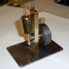
740 forum posts 1043 photos | Finished the turning on the top bearing half's earlier.. I put them into the 3 Jaw to do the other side holding on the recently turned OD. Not much to hold onto but I was taking very light cuts and it did all seem very solid and spinning true - and went ok..
I realised I should have been turning down the 'sides' as well to get the central dimension right as well, not to mention the finish.. So after doing this side I turned around in the chuck and did the other side again.. (hope that makes sense...)
The top bearing half's after turning was finished. If compared with the photo's yesterday, a big improvement.. All done to size now.
The top bearing half's after turning 2. It will be interesting to try a different tool insert for gunmetal as my lathe seems to not be doing the finish I usually get with other materials used so far..
Sorry photo's not great again - not helped by the light in my workshop when the outside doors are closed. I have a 90w, halogen I think it is, just about 4 - 5ft above the Lathe but it's nowhere near good enough. I'm wondering if I can get another type of bulb to fit the 'standard bayonet' holder which is more powerful.. Also wondering how people usually go about polishing or just getting a finish to something like the top (un machined) tops of the bearings - I used to have a Dremel, I'm guessing maybe some use something similar ...? Can do it by hand and some wet and dry of course or emery etc but it seems there's probably an easier or better way.. Have a good bank holiday everyone.. Regards. Allan
|
| Neil Wyatt | 02/05/2014 17:51:32 |
19226 forum posts 749 photos 86 articles | Emery drums in a dremel work wonder on steel , but even then they can be quite aggressive and round corners/edges you want kept sharp. They might chew off gunmetal too fast. Neil |
| JasonB | 02/05/2014 18:05:56 |
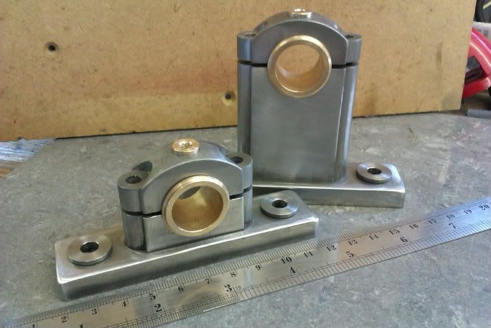
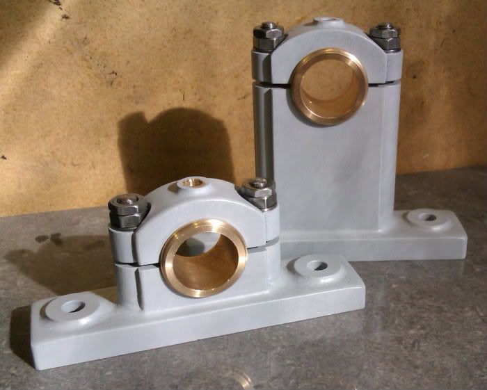
25215 forum posts 3105 photos 1 articles | On a full size engine the bearings and caps would have been separate items with the cap in cast iron. So no need for a mirrored polished surface unless thats what floats your boat. Just clean up with a sharp file and then wrap a bit of 150grit Emery cloth around the file to finish. Myself I would paint the cap and just leave the round bearing bright. These are 150g finish and then painted
J
J |
| GarryC | 02/05/2014 18:35:27 |
740 forum posts 1043 photos | Hi Neil Thanks I've been thinking about getting another dremel, mine went down before starting ME - thinking now it would be useful to have one again.. Hi Jason I had thought about painting the cap - your photo's have totally convinced me, very nice. Painting is yet another skill in its own right of course. I hand painted Victoria but had already thought to have a go at spraying for the No. 1. Its a long ways off and not much thought yet but am thinking maybe car spray paints, primer etc may be possible just to give it a go and improve on hand painting - which wasn't very good at all... Cheers Allan.
|
| Nick_G | 03/05/2014 00:00:05 |
 1808 forum posts 744 photos |
Posted by JasonB on 02/05/2014 18:05:56:
**Nick_G drools. Finest engineering porn if ever I saw it.! Jason. This is decadent deviancy.
Nick |
| GarryC | 03/05/2014 17:54:48 |
740 forum posts 1043 photos | I like the idea of trying to make a little progress most days, no matter how small even when time is difficult - it keeps things moving forward, not always possible but it worked well with Victoria.. So this morning I just separated the bearing half's ready for the next step.. Heating to separate the top bearing half's. It seemed to take a lot more heat to separate them than it did to solder them together.
The top bearing half's after separating 1.
The top bearing half's after separating 2. At this point I wondered if I had over done the heat and ruined them - but after a little rubbing on some wet and dry paper they came up very easily. Think I had to put in a bit more effort than 'normal' for this though in order to get rid of my bad tool marks which were preventing cleaning up properly - hopefully as I'll need to clean them up again shortly after soldering for drilling and boring, it will be easier to do next time around...
The top bearing half's after some cleaning 1.
The top bearing half's after some cleaning 2.
Decided to drill the fixing holes after separating so I could spot face on the Mill in the same way as earlier - next job to do.. Regards Allan.
|
| GarryC | 04/05/2014 19:05:09 |
740 forum posts 1043 photos | Just managed to do the fixing holes and spot face one of the top bearing 'caps' today.. Not long to do.. Checking the size of the fixing nuts a/c for spot facing - used a 10mm End Mill..
Setup used on the Mill to drill the 4mm 2BA Clearance Holes for the bearing 'caps' - and to spot face.. I must get around to lengthening the threads on my clamping studs to avoid having to use so many clamp pieces.. Couldn't use my vice, when I looked carefully the jaws do seem to sometimes be 'rising' or at least pushing the work up when tightened - as Jason suggested they might earlier.. I know the studs won't fit properly unless the holes are bang on vertical.. Have to get a new decent one soon.. The work turned around to do the other side..
Test fitting on the bottom bearing half (just lined up by hand, not fixed) - far from perfect, but not too bad I hope - ready for soldering together, drilling and boring (1)..
Test fitting on the bottom bearing half (just lined up by hand, not fixed) - far from perfect, but not too bad I hope - ready for soldering together, drilling and boring (2)..
The other one to do now. Regards. Allan. ps. can someone yell at me if to many 'small' updates - or if I should go back to just updating when whole parts are finished as I mostly did with Victoria. So quick and easy to upload too much... Edited By Allan. on 04/05/2014 19:09:59 |
| roy entwistle | 04/05/2014 19:53:10 |
| 1716 forum posts | Hi Alan Just a couple of suggestions When you grip something like the two soldered caps in a 4 jaw if possible try not to grip where the join is if the two parts are not exactly the same length you could separate them by tightening the jaws Second point I would have drilled the stud holes 2ba tapping size so that you can spot through for the studs And don't forget to mark both relevant top and bottom bearings so that you keep them together as a pair and also the same way round Hope this helps Roy |
| JasonB | 04/05/2014 20:34:24 |
25215 forum posts 3105 photos 1 articles | So you are not fitting washers then Rather then trying to thread your stud set which will likely have rolled threads anyway, get a bit of M10 studding or the same as the other threads and cut a few short ones. Better to have regular posts then we can help before its possibly too late. Further to what Roy says about holding on the split line which you really need to do to get the hole on the split in a lot of cases. If the blocks are out of line just file then flush and/or put a bit of soft aluminium packing between jaw and work. These caps probably could have been held diagonally which would have held them together rather than risk wedging apart. J |
| GaryM | 04/05/2014 21:16:07 |
 314 forum posts 44 photos | As many updates as you want Allan, we're all temporarily soldered to this thread. Gary |
| GarryC | 04/05/2014 21:31:05 |
740 forum posts 1043 photos | Hi Roy Yes, my mistake - I had meant to say 'tapping' size above (4mm for 2BA) for spotting through (I can't seem to edit it now), and the alarm bells did ring when putting into the chuck - I held them in the 4 Jaw with most holding force' on the 'flat' length, the other 2 jaws just steadying... Will do re marking the bearing pairs and housings. The sole plate casting is very irregular all over not making things any easier - not complaining it may even look better for it I think, maybe how the original was.. Please keep any advice coming - thanks, am very grateful.. Hi Jason I didn't know about rolled threads and have just been reading about how they differ in the 'making' to cut threads - I'll get some extra studding as you suggest, it will be much more convenient to use.. You've got me thinking now if there are washers on the drawings - have to check tomorrow..! Some of the nuts don't seem to be very well made, you can see in some of the photo's, being 'off centre' - or maybe its me looking at everything 'close up' these days since starting ME..! Thanks again.. Thanks Gary! Cheers Allan
Edited By Allan. on 04/05/2014 21:33:37 Edited By Allan. on 04/05/2014 21:40:41 |
| JasonB | 05/05/2014 07:29:14 |
25215 forum posts 3105 photos 1 articles | The "off centre " look is quite possibly due to one side being cut through the crest of the thread and the other the vally but the actual thread will be central. Look at them again with a stud in them and I'm sure they will be OK. This is one reason its best to debur/lightly CSK a hole before its tapped so the CSK follows the true tapping hole and not the thread.
J |
| GarryC | 05/05/2014 11:27:52 |
740 forum posts 1043 photos | Hi Jason Quite right they do look ok when screwed onto a stud.. ! I have to get a deburring tool, its something I've been finding a bit of a issue with, I have nothing at the moment. Going to put on an order from RDG with a Mill Vice if they have one.. The sun must have been getting to me yesterday, a couple of mistakes in writing my last post, another one of course - "with most holding force' on the 'flat' length" - should read something like "most holding force over the tops of the caps"... Just going to do the fixing holes for the second one, post later... Cheers. Allan. |
| Ian S C | 05/05/2014 13:12:34 |
7468 forum posts 230 photos | Allan, there are some (one at least) who would consider it sacrilege it use threaded rod instead of a properly formed stud, but if you do, make sure that the exposed end has a nice radius, the correct number of exposed threads, and all the same hight. Ian S C |
| JasonB | 05/05/2014 16:15:32 |
25215 forum posts 3105 photos 1 articles | Ian, we are talking about studs to hold the clamps to the mill table, not studs for the engine which are a completely different matter Allan you don't really need a deburing tool for small drilled holes you can just twist a larger drill or CSK bit round with your fingers, external corners a fine file will do it sjust large rounded or curved internal corners where a deburring tool is useful. Having said that I did get one of these little sets from Tracy and they are getting quite a bit of use. J |


This thread is closed.
Magazine Locator
Want the latest issue of Model Engineer or Model Engineers' Workshop? Use our magazine locator links to find your nearest stockist!
Sign up to our Newsletter
Sign up to our newsletter and get a free digital issue.
You can unsubscribe at anytime. View our privacy policy at www.mortons.co.uk/privacy
Latest Forum Posts
- *Oct 2023: FORUM MIGRATION TIMELINE*
05/10/2023 07:57:11 - Making ER11 collet chuck
05/10/2023 07:56:24 - What did you do today? 2023
05/10/2023 07:25:01 - Orrery
05/10/2023 06:00:41 - Wera hand-tools
05/10/2023 05:47:07 - New member
05/10/2023 04:40:11 - Problems with external pot on at1 vfd
05/10/2023 00:06:32 - Drain plug
04/10/2023 23:36:17 - digi phase converter for 10 machines.....
04/10/2023 23:13:48 - Winter Storage Of Locomotives
04/10/2023 21:02:11 - More Latest Posts...
- View All Topics
Support Our Partners


Shopping Partners
Subscription Offer

Latest "For Sale" Ads
- Reeves** - Rebuilt Royal Scot by Martin Evans
by John Broughton
£300.00 - BRITANNIA 5" GAUGE James Perrier
by Jon Seabright 1
£2,500.00 - Drill Grinder - for restoration
by Nigel Graham 2
£0.00 - WARCO WM18 MILLING MACHINE
by Alex Chudley
£1,200.00 - MYFORD SUPER 7 LATHE
by Alex Chudley
£2,000.00 - More "For Sale" Ads...
Latest "Wanted" Ads
- D1-3 backplate
by Michael Horley
Price Not Specified - fixed steady for a Colchester bantam mark1 800
by George Jervis
Price Not Specified - lbsc pansy
by JACK SIDEBOTHAM
Price Not Specified - Pratt Burnerd multifit chuck key.
by Tim Riome
Price Not Specified - BANDSAW BLADE WELDER
by HUGH
Price Not Specified - More "Wanted" Ads...
Get In Touch!
Do you want to contact the Model Engineer and Model Engineers' Workshop team?
You can contact us by phone, mail or email about the magazines including becoming a contributor, submitting reader's letters or making queries about articles. You can also get in touch about this website, advertising or other general issues.
Click THIS LINK for full contact details.
For subscription issues please see THIS LINK.
Digital Back Issues


Donate

 Register
 Log-in
Model Engineer Magazine
- Percival Marshall
- M.E. History
- LittleLEC
- M.E. Clock

ME Workshop
- An Adcock
- & Shipley
- Horizontal
- Mill

Subscribe Now
- Great savings
- Delivered to your door

Pre-order your copy!
- Delivered to your doorstep!
- Free UK delivery!
All Forum Topics > Work In Progress and completed items > Stuart 'No.1' : a beginners tale..