Forum sponsored by:

Technical and engineering drawing.
| Bill Pudney | 20/04/2011 01:10:12 |
| 622 forum posts 24 photos | Hi David, About a survey. Those of us up here in Australasia get the magazines some weeks or months after publication in the UK. As a result the closing date for returning surveys is usually long gone. So can you either 1/ Have a later closing date to suit responses from overseas or 2/ Have an online poll cheers Bill Pudney in sunny Adelaide |
| Sam Stones | 20/04/2011 05:32:27 |
 922 forum posts 332 photos |
Geoff, Thanks for your comment. Bob Sheppard (from Harper Green Secondary Modern School, in Farnworth c.1946) holds a very important place in my memory. Tony, I think you’re right. Where are all the responses to the test? Yes, I think you’re right too Steve. It must be too simple a test. I have another anecdote for those of you who are enjoying Terry's thread. I must preface mine by saying that Melburnians have an expression about exposing ones posterior in Burke Street, so here goes. In the late 50's, it became necessary to redesign the outer casing of a toilet cistern. At that time, the casing and lid were being compression moulded from a composite of pitch and other reinforcing materials. The `new’ material was the much more modern thermoplastics polypropylene (PP), and had become commercial around 1957. Unlike the pitch compound, PP could be injection moulded. The specification also included that the existing innards of polyethylene ball valve and syphon, and various metal fittings were to remain. The cistern casing was designed for both `high’ level and `low’ level operation, and for greater adaptability, was identical left to right. It was necessary with this `new’ material to provide parallel wall thickness by local thickening the five inlet/overflow/outlet positions, thus forming `bosses’ on the ends and underneath. The next task was to design and detail the tooling (injection moulds). Eventually, I had produced about half a dozen sheets of tool drawings for the cistern’s lower half. These drawings, having passed through the checkers hands a couple of times, and gained approval at various other levels, were sent off to a German toolmaker. Two injection moulding machines were duly ordered and installed, and after about 6 months the cistern and cistern lid moulds arrived. "Have a look at this!" It was the chief draughtsman. One of the end bosses was missing! But how could that have happened? It turned out that on the GA and also in detail, (having sectioned the mould through various planes to show the feed arrangement, water circuits, air ejection, etc. etc.), I had inadvertently omitted to show that the cistern was actually symmetrical about the vertical centre line. The toolmakers had gone ahead and worked exactly to my drawing. Eventually, the problem was rectified, but by this time I had (coincidentally), taken on a new position with a major raw-material supplier. This company supplied PP, the very supplier of the grade being used for the cistern!!!? Guess what? The bl . . y cistern followed me there with another problem. But that’s yet another story. They say things come back to haunt you. But surely not twice. A couple of evenings ago, my wife and I were watching a very early `On the Buses’ episode. Bus driver, Stan Butler was replacing their old toilet cistern with a modern low-level version, and as usual, he was getting into all sorts of bother. You’ve guessed it! He was installing the very same cistern which I designed (and helped to screw-up), all those years ago.
AND, the point is, besides following my story, have you understood some of my deliberately placed design engineering jargon? If not, then Terry's objective gains more validity.
Best regards to all,
Sam
Edited By Sam Stones on 20/04/2011 05:33:50 Edited By Sam Stones on 20/04/2011 05:35:29 |
| David Clark 1 | 20/04/2011 09:04:51 |
 3357 forum posts 112 photos 10 articles | Hi There
I never put a closing date on the survey.
If there is one it has been added by someone else.
Last time, I waited for all the surveys to came back and
gave out the prizes a couple of weeks after they stopped arriving.
No more were received.
regards David |
| David Clark 1 | 20/04/2011 09:10:11 |
3357 forum posts 112 photos 10 articles | Hi There
I think more readers of MEW need it than readers of ME.
Most ME readers have been reading for many years and have gained a lot of knowledge.
regards david |
| Gordon W | 20/04/2011 10:18:47 |
| 2011 forum posts | Graham, just read your earlier post, I would be happy to proof-read ,or act as checker for drawings. But as been pointed out already, there will still be mistakes, or what people see as mistakes. I still have some old BS308's. I was a contract draffy ( self employed) for years, long before employment rights etc. If you were no good at the job it was "don't bother coming tomorrow" Every company I worked for had their own methods and standards, If I was doing a drawing for , maybe a small co., I would use my own standards, mainly all views and sections clearly labeled. BS308 is for guidance ,but still the best basics. CAD has produced some dreadful results, mainly because anyone can use it, and knowledge of what is happening is not required. |
| Geoff Sheppard | 20/04/2011 10:36:41 |
| 80 forum posts 1 photos | Sam
The little problem you set us and the mention of spatial awareness jogged my memory and took me back quite a few years. A colleague Development Engineer was having a problem with an engine component, so laid hands on one and examined it thoroughly. He soon worked out what the problem was and devised a design change which he thought would fix it. The task was to now convince the project's Chief Designer (VERY important in the hierarchy) that a) there was a problem and b) his solution would fix it, so he marches along to the great man bearing the offending object. After carefully explaining chapter and verse he was astonished when the designer said that he couldn't really appreciate the problem without the drawing in front of him. This despite the fact that all was plain to see. It is all too easy to get mesmerised by the theoretical and lose sight of the real world.
By the way, your challenge really had me delving into the memory bank. This sort of 'teaser' was very popular in the Training Drawing Office, with students trying to out-do each other with more and more obscure examples.
Geoff |
| Steve Garnett | 20/04/2011 10:58:18 |
| 837 forum posts 27 photos | Posted by Sam Stones on 20/04/2011 05:32:27: Tony, I think you’re right. Where are all the responses to the test? Yes, I think you’re right too Steve. It must be too simple a test. Well, ady's response was interesting. If technical drawing of this nature allowed perspective, and ady had added just one more dotted line, he'd have been correct. And the answer would have been the same if it had been either side, the underneath or the back view you'd asked for! Edited By Steve Garnett on 20/04/2011 10:58:51 |
| ady | 20/04/2011 12:05:18 |
| 612 forum posts 50 photos | Well, ady's response was interesting. If technical drawing of this
nature allowed perspective, and ady had added just one more dotted
line, he'd have been correct. I never got less than 90% at techie drawing...used to show the teacher his mistakes... Taught myself to build CAD gearboxes in my head from haynes manuals at one point, many years ago. Finished the Merchant navy perspective test(add a line to complete the boxy type shape) when you weren't actually supposed to get to the end of the 40 odd questions in 2 minutes. This is my first techie drawing answer since 1976. I'm hoping the middle box doesn't represent a spoof engraving and is part of something visually amazing, like a donut. (My answer was actually a "right back at ya" test to see if anyone could see what I was getting at. well spotted) Edited By ady on 20/04/2011 12:09:39 |
| The Merry Miller | 20/04/2011 13:21:03 |
 484 forum posts 97 photos | I would like to recommend to any modeller who aspires to greatness in the interpretation of engineering drawings to get hold of a copy of the following hardbacked book. "Interpreting Engineering Drawings -metric edition" by Cecil H Jensen & Raymond D Hines. Readily available on Amazon. It's an American book but very pertinent to our own scheme of things with an incredible amount of detail and data. I bought a copy for my son when he was studying hoping he might discover some latent engineering genes in his body, but no, the fool went into banking! |
| Geoff Sheppard | 20/04/2011 14:03:52 |
| 80 forum posts 1 photos | How about a verbal description of the figure shown in Sam's puzzle?:-
"A solid object formed by slicing a cube of side x diagonally from top to bottom. Superimposed on the resulting sloping face is a section of a second, smaller cube, similarly sliced, the two arranged sloping face to sloping face."
I'm sure that someone can make a better job of it than that.
Geoff |
| Geoff Sheppard | 20/04/2011 14:03:53 |
| 80 forum posts 1 photos | How about a verbal description of the figure shown in Sam's puzzle?:-
"A solid object formed by slicing a cube of side x diagonally from top to bottom. Superimposed on the resulting sloping face is a section of a second, smaller cube, similarly sliced, the two arranged sloping face to sloping face."
I'm sure that someone can make a better job of it than that.
Geoff |
| ady | 20/04/2011 14:04:22 |
| 612 forum posts 50 photos | and if ady had added just one more dotted line, he'd have been correct. I reckon that if I removed the top right hand dotted line then it could be right, the curvature of the donuts could meet at the top right hand corner of the inner box, merging seamlessly along the line which is deleted. Edited By ady on 20/04/2011 14:14:07 |
| Terryd | 20/04/2011 14:22:53 |
 1946 forum posts 179 photos | Posted by ady on 20/04/2011 14:04:22: and if ady had added just one more dotted line, he'd have been correct. I reckon that if I removed the top right hand dotted line then it would be correct. Hi Ady, Actually there should be no dotted lines. As Sam said in his original post, there is no hidden detail on the drawings and dotted lines are used to show such detail. Best regards Terry |
| David Clark 1 | 20/04/2011 15:32:53 |
3357 forum posts 112 photos 10 articles | Hi there
Readily availble but not very cheap.
£50 or £60 at least for an up to date edition.
regards David
|
| The Merry Miller | 20/04/2011 15:46:35 |
484 forum posts 97 photos | Hi David, You may have been looking at the Jensen & Helsel editions at that price. The version I have is from 1979 (Jensen & Hines) and is still very pertinent in todays times believe me. Used later versions are available from a couple of quid, not all in hardback. |
| Steve Garnett | 20/04/2011 17:34:48 |
| 837 forum posts 27 photos | Posted by Terryd on 20/04/2011 14:22:53: Actually there should be no dotted lines. As Sam said in his original post, there is no hidden detail on the drawings and dotted lines are used to show such detail. Terry is absolutely correct, of course. And that's why I said previously that ady's dotted lines would only be correct if he added one, and perspective was allowed, because they could represent the outside edges of a cube - which we could legitimately establish from the plan and front view, although that's not the only option, as Geoff has pointed out. But of course perspective isn't allowed, so I repeat - what do those two inner squares actually represent on the plan and front views? Edited By Steve Garnett on 20/04/2011 17:49:14 |
| Les Jones 1 | 20/04/2011 18:06:06 |
| 2292 forum posts 159 photos | Hi all, I'm prepared to admit that I haven't worked out the answer. Les. |
| Steve Garnett | 20/04/2011 18:37:55 |
| 837 forum posts 27 photos | I'm getting bored with this now, so I'll tell you my take on it - and that's basically that there isn't enough information to give you a single definitive answer to the side view. I think there may be two possibilities only, though. One is the diagonal cut, as Geoff mentions (with or without inner cube) - and the implication of this is that the central square isn't necessarily a square at all, but a rectangle, and it's just drawn on the cut as such - but then it won't show from the side. The other is, of course, that it's a cube with two squares drawn on it as shown, and from the side, once again, no inner square will be visible. With other options for the diagonal plane (such as curves) you run into problems with needing the rectangle to move position between the plan and front views, so they're out. All other options appear to require detail lines on either the plan or the front view, so they're out too. Have I missed any other possibilities that don't involve hidden detail? Edited By Steve Garnett on 20/04/2011 18:48:06 |
| Steve Garnett | 20/04/2011 19:33:54 |
| 837 forum posts 27 photos | Well, since unreferenced lines are allowed on drawings (although this is like steam trains whistling in stations - not wrong; we just don't do it), here are two solutions sketched. The first is Geoff's one - probably the neatest way. But the second isn't absolutely wrong either. You can work out what the side views of each would be very easily, I think: 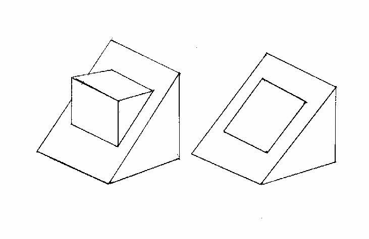 I prefer Geoff's. Sorry for the awful sketch, but you get the idea... and you don't want me to draw a cube, now, do you? Not if it looks that bad anyway! |
| Les Jones 1 | 20/04/2011 19:34:40 |
| 2292 forum posts 159 photos | Hi Gray, Thanks for making me read Geoff's explanation a second time (and understanding it this time.) I think my rigid preconception that it had to be a cube even hindered my understanding of Geoff's explanation on the first reading. Geoff, I do not think there is anything wrong with your description of the object - it describes it perfectly. Les. Edited By Les Jones 1 on 20/04/2011 19:36:37 |
Please login to post a reply.
Magazine Locator
Want the latest issue of Model Engineer or Model Engineers' Workshop? Use our magazine locator links to find your nearest stockist!
Sign up to our Newsletter
Sign up to our newsletter and get a free digital issue.
You can unsubscribe at anytime. View our privacy policy at www.mortons.co.uk/privacy
Latest Forum Posts
- *Oct 2023: FORUM MIGRATION TIMELINE*
05/10/2023 07:57:11 - Making ER11 collet chuck
05/10/2023 07:56:24 - What did you do today? 2023
05/10/2023 07:25:01 - Orrery
05/10/2023 06:00:41 - Wera hand-tools
05/10/2023 05:47:07 - New member
05/10/2023 04:40:11 - Problems with external pot on at1 vfd
05/10/2023 00:06:32 - Drain plug
04/10/2023 23:36:17 - digi phase converter for 10 machines.....
04/10/2023 23:13:48 - Winter Storage Of Locomotives
04/10/2023 21:02:11 - More Latest Posts...
- View All Topics
Support Our Partners


Shopping Partners
Subscription Offer

Latest "For Sale" Ads
- Reeves** - Rebuilt Royal Scot by Martin Evans
by John Broughton
£300.00 - BRITANNIA 5" GAUGE James Perrier
by Jon Seabright 1
£2,500.00 - Drill Grinder - for restoration
by Nigel Graham 2
£0.00 - WARCO WM18 MILLING MACHINE
by Alex Chudley
£1,200.00 - MYFORD SUPER 7 LATHE
by Alex Chudley
£2,000.00 - More "For Sale" Ads...
Latest "Wanted" Ads
- D1-3 backplate
by Michael Horley
Price Not Specified - fixed steady for a Colchester bantam mark1 800
by George Jervis
Price Not Specified - lbsc pansy
by JACK SIDEBOTHAM
Price Not Specified - Pratt Burnerd multifit chuck key.
by Tim Riome
Price Not Specified - BANDSAW BLADE WELDER
by HUGH
Price Not Specified - More "Wanted" Ads...
Get In Touch!
Do you want to contact the Model Engineer and Model Engineers' Workshop team?
You can contact us by phone, mail or email about the magazines including becoming a contributor, submitting reader's letters or making queries about articles. You can also get in touch about this website, advertising or other general issues.
Click THIS LINK for full contact details.
For subscription issues please see THIS LINK.
Digital Back Issues


Donate

 Register
 Log-in
Model Engineer Magazine
- Percival Marshall
- M.E. History
- LittleLEC
- M.E. Clock

ME Workshop
- An Adcock
- & Shipley
- Horizontal
- Mill

Subscribe Now
- Great savings
- Delivered to your door

Pre-order your copy!
- Delivered to your doorstep!
- Free UK delivery!
All Forum Topics > CAD - Technical drawing & design > Technical and engineering drawing.