Forum sponsored by:

3 -Phase Conversion of a Mini-Lathe
A new online article
Articles
3-Phase Conversion and Other Alternative Methods of Powering a Mini-Lathe
After much experimentation with different ways of powering my mini-lathe on a keep it going basis, I finally decided to go the whole hog and install an inverter and 3-phase motor – to give me variable frequency drive. This is the whole story.
| Ron Laden | 16/12/2018 10:56:23 |
 2320 forum posts 452 photos | This is a beginners question so dont shoot me down in flames. I guess you guys obviously looked into it before you started but it would make me wonder is a mini-lathe capable of handling all this extra power..? Ron p.s. I have just seen on Ian,s earlier post 750 watts, so not that much of an increase I was thinking the motors are 1.5 - 2 HP or something similar. Edited By Ron Laden on 16/12/2018 11:04:20 Edited By Ron Laden on 16/12/2018 11:06:41 |
| not done it yet | 16/12/2018 11:16:21 |
| 7517 forum posts 20 photos | If you are actually considering 1500W, you would only have yourself to congratulate if you broke it. Reducing the speed may result in constant torque with modern-day inverters, but remember torque and power are related through the rotational speed. Simple belt and pulley speed reductions retain the power (most of it) and increase torque. It is usually torque that breaks things (unless one has a high speed crash!).
|
| I.M. OUTAHERE | 16/12/2018 11:30:34 |
| 1468 forum posts 3 photos | If you crash the machine it won't matter much if its 1/2 hp or 1 hp you are going to break something . You just have to remember to drive it like the lower power unit even though the power and temptation is there to push it harder . I still have the nylon gears in the tumbler as they act as a safety stop for the leadscrew and i do intend to play with the belt tension of the poly v belt to allow some slip if i get to aggressive with the machine . I'm hoping that the weight of the motor will be sufficient for the v belt tension but I won't know that until i use the machine and this would also allow some slip if needed . The motor is actually a 0.55 kw unit so 3/4 hp , i always thought it was a 1 hp unit - why i dunno. Never going to shoot a newcomer down in flames for asking a question Ron! If you don't ask you never learn ! Edited By XD 351 on 16/12/2018 11:33:51 |
| Martin Newbold | 16/12/2018 11:43:47 |
| 415 forum posts 240 photos | Am not really sure what you are trying to do from the conversations . Are you trying to find a three phase inverter to power it as its already three phase ? or are you looking to change the motor and power source? XD has already given you feedback on nylon gears and torque and its something you should check. |
| SillyOldDuffer | 16/12/2018 11:55:43 |
| 10668 forum posts 2415 photos | Posted by Ron Laden on 16/12/2018 10:56:23:
This is a beginners question so dont shoot me down in flames. I guess you guys obviously looked into it before you started but it would make me wonder is a mini-lathe capable of handling all this extra power..? Ron
Looking at the detail, the article isn't suggesting using much more powerful motors, just changing the type. Electric motors come in a bewildering variety of types, and not all are good for driving a lathe. Keeping it simple, in order of desirability:
When I had a mini-lathe, I would only have upgraded it had I written off the motor and electronics. The DC motor as fitted is well-suited to the machine, so like for like replacement is sensible. You might feel different if you happen to have a spare 3-phase motor and VFD to hand, or found that a 3-phase package was cheaper or more easily sourced than a replacement DC motor/controller set. I wouldn't go out of my way to replace a mini-lathe's DC motor with 3-phase just to improve it. Likewise, it would make more sense in theory to upgrade a Myford lathe's 'grotty' single-phase motor to 3-phase+VFD, but in practice Myford owners manage perfectly well with single-phase. It might be better in theory to convert, but doing so unless there's an actual improvement is just wasting time and money. Dave Edit : just saw the PS! Putting more than 600W on to the spindle of a minilathe is overkill, 750W is probably the safe maximum. Deliberately putting 2HP on a mini-lathe with the intention of using it would be insane! Edited By SillyOldDuffer on 16/12/2018 11:59:52 |
| I.M. OUTAHERE | 16/12/2018 12:14:20 |
| 1468 forum posts 3 photos | The reason this lathe was set up with a VFD and 3 ph motor was because when I bought it off ebay it had been dropped off a forklift damaging the cross feed screw and gear cover , this meant it was used as a spare parts machine so it came with no motor or controller . The VFD cost the same as a replacement driver board and the motor was similar . Back then brushless motors were not around - well not on mini lathes anyhow , it was bought as a stuff around with it project in mind .
|
| Neil Wyatt | 16/12/2018 13:09:08 |
 19226 forum posts 749 photos 86 articles | Posted by XD 351 on 16/12/2018 11:30:34:
i do intend to play with the belt tension of the poly v belt to allow some slip if i get to aggressive with the machine . I'm hoping that the weight of the motor will be sufficient for the v belt tension but I won't know that until i use the machine and this would also allow some slip if needed . I found that I needed to put a fair bit of extra tension on the belt, although this was exaggerated by the acute angle my tensioner works at. |
| Neil Wyatt | 16/12/2018 13:13:00 |
19226 forum posts 749 photos 86 articles | The arrangement with the Hoover motor was actually really nice to use although it needed an extra weight on top to stop slipping. I did miss having a speed below 200rpm though. Neil |
| I.M. OUTAHERE | 17/12/2018 10:51:55 |
| 1468 forum posts 3 photos | Now that i have the motor bolted on and the v belt fitted i can see what you mean Neil ! I will have to make up some sort of arrangement to pivot the motor up to change speeds and i am thinking of using a mechanism similar to a car handbrake to lock the motor down and tension the belt . |
| Robert Atkinson 2 | 17/12/2018 16:25:01 |
 1891 forum posts 37 photos | Reading the original conversion article, despite the abundance of safety warnings the system does not comply with basic electrical safety, machine safety or emissions requirements. Most importantly the "E" stop should break the input supply to the drive. This could be direct or via a no-volt release contactor wired to the LV stop. The latter is best as if there is no drive failure the drive will bring the machine to a stop faster than just cutting the power. You have to cut the power as well to cover for a drive control failure. A E stop on just a control input is not good enough. To comply with low voltage regulations (and common sense safety) this type of drive must be fitted inside a protective enclosure. The control panel wiring should use screened cable. To comply with emissions regulations the particular drive shown needs an external input filter. (the CUB inverters with an "E" suffix to the part number have a filter built in and come with an earthing plate) A good filter can cost as much as the drive. Technically you then have to get it tested for emissions before using it (yes even as a personal item). Testing may be a bit much, but a decent filter is essential. Not trying to stop people doing "DIY" but we should at least try to do things correctly. Robert G8RPI.
|
| Neil Wyatt | 17/12/2018 18:16:45 |
19226 forum posts 749 photos 86 articles | The contactor suggestion is a useful one. I'm assuming you mean cut the mains power with a relay/contactor? Wil the unit still brake the motor to a quick halt if you cut the mains power? It's not obvious from the photo but the thick green wire going to the control panel wire is an earth wire connected to the cable screen. The EMC directive came into force in April 2016, the article was published in June 2014. It's not practical for us to revise all historic articles (there are thousands of them on this site if you include back issues). Neil
|
| Robert Atkinson 2 | 17/12/2018 19:38:00 |
1891 forum posts 37 photos | Posted by Neil Wyatt on 17/12/2018 18:16:45:
The contactor suggestion is a useful one. I'm assuming you mean cut the mains power with a relay/contactor? Wil the unit still brake the motor to a quick halt if you cut the mains power? It's not obvious from the photo but the thick green wire going to the control panel wire is an earth wire connected to the cable screen. The EMC directive came into force in April 2016, the article was published in June 2014. It's not practical for us to revise all historic articles (there are thousands of them on this site if you include back issues). Neil
Hi, I thought the green wire was a screen but it's not mentioned and not in the circuit diagram. The current version of the EMC Directive may be dated 2014 but the original was 1989 and the law requiring comliance in the UK came into force in 1996. Robert G8RPI. Edited By Robert Atkinson 2 on 17/12/2018 19:41:30 |
| Neil Wyatt | 17/12/2018 20:05:47 |
19226 forum posts 749 photos 86 articles | Could you point me at a plain English guide to the EMC directive and DIY users? I can't see any mention of end users in the Government guidelines. www.gov.uk/government/publications/electromagnetic-compatibility-regulations-2016 Neil |
| Robert Atkinson 2 | 18/12/2018 07:45:28 |
1891 forum posts 37 photos | Hi Neil, I'll try to find a reference but most are for manufacturers and importers. The obligation for conformity happens when a item is put on the market or is first put into use. The VFD's despite having CE marks are components and only comply with the directives if the manufacturers instructions are followed. Generally this means filters, enclosures and safety devices. Having tested many items using VFDs and electrically similar servo drives, I can say that they won't pass without significant work. There is no dispensation in the EMC directive for one-offs or personal use. The only dispensations are for electronic development kits for professional use in R&D facilities and for radio amateurs. Note that you have to be compliant, you don't HAVE to test. I feel a reasonable hobby approach is to use filters and enclosures (for electrical safety under the low voltage directive) as recommended by the manufacturer. While machinery and LCD "failures" only put you and others in your workshop at risk (maybe neighbours if it catches fire), EMC can affect many services even some distance away. These include "safety of life" systems such as emergency services radios and aircraft navigation systems.
Robert G8RPI CEng MRAeS |
| Neil Wyatt | 18/12/2018 13:27:35 |
19226 forum posts 749 photos 86 articles | The difficult bit is not fitting a filter but knowing whether it is effective or not. the manual gives no guidance, it just suggest fitting 'a filter'. At present an fm radio 50 cm from the inverter can't pick up anything. On am it picks up a modest hum audible up to about 15 metres away, but even close to the unit the signal is not strong enough to overcome a distant station. I could set up my computer and SDR to see what broadband radiation there is. But there will always be something how can I tell if it's a problem or not? I have hat I would consider a suitable filter, but at the moment it's built into something else (a PWM lathe speed controller of similar power). Neil Edited By Neil Wyatt on 18/12/2018 13:28:22 |
| SillyOldDuffer | 18/12/2018 14:52:58 |
| 10668 forum posts 2415 photos | Posted by Neil Wyatt on 18/12/2018 13:27:35:
... I could set up my computer and SDR to see what broadband radiation there is. But there will always be something how can I tell if it's a problem or not? ...EMC problems are usually pretty obvious on a Software Defined Radio. I happen to be trying to sort a serious EMC problem out at the moment. Here's some screenshots from SDRs at a quiet location in Weston-Super-Mare compared with what I get in a noisy village about 40 miles away. First. This is Weston's view of about 30 seconds worth of the entire radio spectrum from 0-30MHz. No signal is black, then with increasing strength up through white, green, yellow and red. Genuine signals are narrow vertical lines, noise tends to be broad. Most of the light blue in this screenshot is a mixture of man-made and natural noise. There's quite a lot of noise, but this is fairly good.
In comparison here's what's received at my home:
Note the almost total absence of man-made signals! My SDR is almost deafened by man-made noise. The horizontal lines most obvious on the right are Ethernet signals, probably leaking from an IP over Powerline system nearby. Much of the white fog is VDSL (Broadband Internet) leaking from telephone lines, probably because neighbours have unbalanced their feeds by fitting extension cabling inside their homes. (This also reduces download speed.) The wavy wide green, yellow and orange vertical streaks are caused by switch-mode power supplies - cheap ones are rarely well filtered. A major problem living in a village is that all the power-lines are strung between poles. Any radio muck that escapes past a filter can be radiated by miles of cabling acting as a good antenna. Most homes these days have some leaky electronics - if my home is typical about 90% of devices are fine, and about 10% are rogue. The fun really starts when I turn on my lathe. The extra noise generated by the VFD is very obvious at the bottom of the screen.
I feel guilty about my noisy lathe. I improved it slightly last year by fitting well-screened cable between motor and VFD, but I haven't tried any filters yet. When playing lathes I'm not listening to shortwave radio. Domestic radios aren't good at detecting EMC issues - they're rather deaf, and sharply tuned to loud local broadcasts. If interference can be heard on an ordinary radio you have a major problem. If you have filters please use them. Also avoid counterfeit and very cheap switch-mode power supplies. And if something's not in use, unplug it! If you happen to own an SDR, it's worth checking what you can hear against an internet accessible SDRs, Try sdr.hu and websdr.org Dave
Edited By SillyOldDuffer on 18/12/2018 14:57:38 |
| Robert Atkinson 2 | 18/12/2018 21:51:06 |
1891 forum posts 37 photos | Great post Dave. Generally any filter is better than none. Make sure it is rated at a high enough current. Physically larger or higher current is generally better. Only fit to the input of the VFD. Do NOT fit a filter between the VFD and motor unless it is specifically designed for that drive and motor. Keep leads between the filter and VFD as hort and direct as possible. Ideally mount drive and filter in a grounded metal box or at least mount both filter and VFD directly on a metal (light alloy) plate. Keep leads between VFD and motor short too. A Corcom 10EMC1 is a good example of a dual stage filter that will help a lot with noise from VFDs and is reasonably priced.
https://uk.farnell.com/corcom-te-connectivity/10emc1/filter-10a-1-phase/dp/9586474?st=power%20filter Similar and probably slightly better performing is the Schurter 5500.2603.01 https://uk.farnell.com/schurter/5500-2603-01/ac-filter-1-phase-10a-250v/dp/2134492?st=power%20filter Hopefully it's obvious that the filter needs to be in a box or otherwise protected from contact with persons or swarf. Robert G8RPI.
Edited By Robert Atkinson 2 on 18/12/2018 21:51:59 |
| I.M. OUTAHERE | 21/12/2018 05:24:41 |
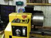
| 1468 forum posts 3 photos | Here is the general arrangement of th belt tenshioner , nothing special just a sliding spring loaded block that locks into the grooves in the shaft . I still have to make a handle withthe mechanism to make pulling up the sliding block ( screwed to the end of the cap screw and is located in a slot in the main body ) . This arrangement also allows the motor to be locked forward so the belt is loose .
Edited By XD 351 on 21/12/2018 05:28:16 |
| HughE | 21/12/2018 07:35:23 |
| 122 forum posts | When I fitted the VFD to my S7 I first tested the setup on the bench. The EMI was very obvious causing some electronic gadgets in the workshop to fail. I fitted the Schurter filter as identified by Robert and fitted the whole assembly in a shield diecast box. There are now no obvious EMI problems. Just received my SDR kit from BG , will try SODs tests when I have got it going . Out of interest in the latest EPE there is a 2 part article on making a speed controller for single and three phase motors. Edited By HughE on 21/12/2018 07:36:00 |
| I.M. OUTAHERE | 21/12/2018 09:48:11 |
| 1468 forum posts 3 photos | If all the above is true then there needs to be a dedicated thread for VFD interference issues because anyone wanting to use one on any lathe needs to be aware of this . There is no reason why you couldn't use the same set up shown with a dc treadmill motor . I am not trying to promote the virtues of a vfd set up , just show how i have done it and so that those who may be interested may gain some insight or ideas . With my ultrasonic cleaner i fitted a commercially available unit because one of the driver boards had failed and destroyed the inductor so the new filter covered all the boards . When i was a kid i worked out that a small dc motor running flat out would cause an interference stripe across the tele which drove my old lady mad especially when the daily soap opera was on - she never worked out what caused it otherwise I wouldn't be here .🤪 Edited By XD 351 on 21/12/2018 10:02:24 |


Please login to post a reply.
Magazine Locator
Want the latest issue of Model Engineer or Model Engineers' Workshop? Use our magazine locator links to find your nearest stockist!
Sign up to our Newsletter
Sign up to our newsletter and get a free digital issue.
You can unsubscribe at anytime. View our privacy policy at www.mortons.co.uk/privacy
Latest Forum Posts
- *Oct 2023: FORUM MIGRATION TIMELINE*
05/10/2023 07:57:11 - Making ER11 collet chuck
05/10/2023 07:56:24 - What did you do today? 2023
05/10/2023 07:25:01 - Orrery
05/10/2023 06:00:41 - Wera hand-tools
05/10/2023 05:47:07 - New member
05/10/2023 04:40:11 - Problems with external pot on at1 vfd
05/10/2023 00:06:32 - Drain plug
04/10/2023 23:36:17 - digi phase converter for 10 machines.....
04/10/2023 23:13:48 - Winter Storage Of Locomotives
04/10/2023 21:02:11 - More Latest Posts...
- View All Topics
Support Our Partners


Shopping Partners
Subscription Offer

Latest "For Sale" Ads
- Reeves** - Rebuilt Royal Scot by Martin Evans
by John Broughton
£300.00 - BRITANNIA 5" GAUGE James Perrier
by Jon Seabright 1
£2,500.00 - Drill Grinder - for restoration
by Nigel Graham 2
£0.00 - WARCO WM18 MILLING MACHINE
by Alex Chudley
£1,200.00 - MYFORD SUPER 7 LATHE
by Alex Chudley
£2,000.00 - More "For Sale" Ads...
Latest "Wanted" Ads
- D1-3 backplate
by Michael Horley
Price Not Specified - fixed steady for a Colchester bantam mark1 800
by George Jervis
Price Not Specified - lbsc pansy
by JACK SIDEBOTHAM
Price Not Specified - Pratt Burnerd multifit chuck key.
by Tim Riome
Price Not Specified - BANDSAW BLADE WELDER
by HUGH
Price Not Specified - More "Wanted" Ads...
Get In Touch!
Do you want to contact the Model Engineer and Model Engineers' Workshop team?
You can contact us by phone, mail or email about the magazines including becoming a contributor, submitting reader's letters or making queries about articles. You can also get in touch about this website, advertising or other general issues.
Click THIS LINK for full contact details.
For subscription issues please see THIS LINK.
Digital Back Issues


Donate

 Register
 Log-in
Model Engineer Magazine
- Percival Marshall
- M.E. History
- LittleLEC
- M.E. Clock

ME Workshop
- An Adcock
- & Shipley
- Horizontal
- Mill

Subscribe Now
- Great savings
- Delivered to your door

Pre-order your copy!
- Delivered to your doorstep!
- Free UK delivery!
All Forum Topics > Workshop Tools and Tooling > 3 -Phase Conversion of a Mini-Lathe