Forum sponsored by:

New technology in Model Engineers Workshop
The way forward.
| Flying Fifer | 20/05/2011 23:27:11 |
| 180 forum posts | They are!!! Well said John. |
| Chris Trice | 20/05/2011 23:41:38 |
 1376 forum posts 10 photos | Hear hear.
 |
| John Stevenson | 20/05/2011 23:53:59 |
 5068 forum posts 3 photos | They are OK if you like a 64 year old design with flat soft bed and plain bearings. I wonder when we will see a metric version with metric leadscrew ? John S. |
| NJH | 21/05/2011 10:08:07 |
 2314 forum posts 139 photos | Well John As a 66 year old myself I certainly prefer a flat soft bed ! ( I also have a Myford and it works for me - there are others I might prefer but I couldn't possibly justify the cost.) Regards Norman |
| Chris Trice | 21/05/2011 10:14:22 |
1376 forum posts 10 photos | I have induction hardened bedways and they're as good as new but i admit not having the option of a metric leadscrew always struck me as an omission. |
| John Stevenson | 21/05/2011 11:32:42 |
5068 forum posts 3 photos | Posted by NJH on 21/05/2011 10:08:07: Well John As a 66 year old myself I certainly prefer a flat soft bed ! Regards Norman That's OK if you turn in your sleep  Can you imagine what the bottom line would be IF they were ever to offer a Myford with metric leadscrew AND metric quick change box ? The people who presently say they can't justify the cost wouldn't need to, they would be dead of a heart attack. John S. |
| David Clark 1 | 21/05/2011 12:09:11 |
 3357 forum posts 112 photos 10 articles | Derek Brown
Has a metric conversion available for the Myford gearbox.
Described in the current MEW I think.
regards david |
| KWIL | 21/05/2011 12:21:56 |
| 3681 forum posts 70 photos | Derek Brown's Metric Conversion System works very and is quick to change. I have one on my Myford PCF Super 7 since it was first published in ME some years ago. Yes John S I also have other lathes including Harrison M300 so that does not make me solely pro Myford, in any case the flat bed plain bearings only really applies to the ML7. |
| NJH | 21/05/2011 13:06:43 |
2314 forum posts 139 photos | Hi John Well happily my Myford S7B PCF is in good nick ( probably better than I am !), has all the bells and whistles and is, I'm sure, capable of producing anything I may ask of it. I just need to learn a bit more so that I ask it the right questions! As far as metric threads go it's not been a problem so far and Kwil's reply offers a route if that becomes an issue. I only make things to suit myself so will use threads that I can produce. I doubt that I will ever buy another lathe so I must "love" this one. As far as my being unable to justify the cost of a better machine I wasn't thinking of a larger or "metrified" Myford . I am a mere amateur but have, on occasion, used Lorch, Schaublin and Hardinge lathes - all superb ! If I ever win the lottery ( unlikely as I don't enter) then I will have a wonderful spending spree but until then I will continue to enjoy using my existing stuff and the satisfaction I receive when it all turns out as planned. ( I try to forget the anguish when it doesn't!) Of course if I ever get bored I can flog it all on ebay, buy all the CNC kit and turn into a " New Age" Model Engineer (N.A.M.E.)  Regards Norman |
| John McNamara | 21/05/2011 18:03:29 |
 1377 forum posts 133 photos | Hi All Maybe the easiest way to consider what changes are made using mineral casting is to try redesigning a known design. The Warden design Grinder is a good starting point. A simple machine made from sheet metal. In the drawings below the base, Motor support pillar and the sliding end plates have been redesigned to use Mineral castings. The Base is a 50mm cast slab all mounting holes will be placed by casting in pre drilled and counterbored 50mm long sleeves of mild steel, the outer surface of the sleeve to be knurled or slightly ribbed in the lathe; this will remove any possibility of them being driven out. Light 8mm steel reinforcement will be placed around the periphery and in a 100mm grid pattern. The motor pillar is a solid cast block that will be epoxy resin glued to the base. This will form an extremely solid mount for the motor. Epoxy Concrete has about 8 times the damping of cast iron and a great many times more than that compared to sheet metal. This should greatly reduce vibration and improve the surface finish obtainable. I chose to draw a .5hp frame size motor, although there is room for a larger rating if required. I provided for a taper lock removable wheel mount so that multiple wheels could be easily changed and remain centered. While reviewing the sheet metal design I decided to make the table movable in both the x and y direction. In addition to the angle Z plane. Note the two knurled knobs for adjustment. These would turn simple feed screws loaded against a spring to remove any backlash. Note the thickness of the end plates, provisionally 50mm, this allows 25mm holes to be cast in for the round shaft rails. I deliberately chose this size to get a large bearing area. As cast the clearance will be between .0001 and .0003. The gap being the release agent applied to the shaft to stop it sticking. This is where cold casting really excels. Alternatively precision bushes could be cast in or bush retainers if you want to take a belt and braces approach and have replaceable bushes. The table is 12mm steel Supported on steel bearing blocks screwed to the underside transferring the table load to the 20mm steel shaft that runs between the end plates. The end plates again greatly improve damping (The table angle adjustment cams are not shown I want to review that design) This is a concept design it is not finalized, however it would not take a lot of work to make it so, unless inspiration takes charge forcing a redesign. The casting process is no different to working with cement. The aggregate mix of 5-8mm graded aggregate, ideally rounded pebbles and washed silica sand for the base and coarse washed silica sand only for the end plates is mixed with approximately 9 – 12 % Epoxy by weight. Ideally less is better. This week I take delivery of the epoxy I have chosen to test. I will report back my findings. Cheers John McNamara 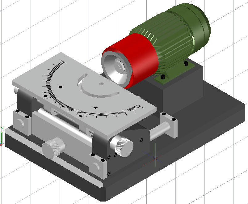 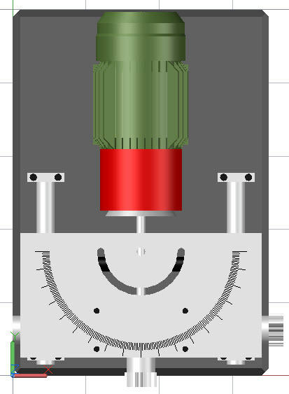 Edited By John McNamara on 21/05/2011 18:22:16 |
| blowlamp | 21/05/2011 18:19:18 |
 1885 forum posts 111 photos | OH MY GOD!... He's done CAD drawings as well!!... When's it going to end ...Aghh!!
Martin. |
| John McNamara | 21/05/2011 18:49:48 |
1377 forum posts 133 photos | Criticism Carl Sagan said of Plato: "Science and mathematics were to be removed from the hands of the merchants and the artisans. This tendency found its most effective advocate in a follower of Pythagoras named Plato." and: "He (Plato) believed that ideas were far more real than the natural world. He advised the astronomers not to waste their time observing the stars and planets. It was better, he believed, just to think about them. Plato expressed hostility to observation and experiment. He taught contempt for the real world and disdain for the practical application of scientific knowledge. Plato's followers succeeded in extinguishing the light of science and experiment that had been kindled by Democritus and the other Ionians."[ This IS a thread about new technology. We don't just think about it we do it. Thank You John McNamara Edited By John McNamara on 21/05/2011 18:52:57 |
| NJH | 21/05/2011 19:54:26 |
2314 forum posts 139 photos | Hi John No Philosophy please - we've had rather too much of that lately! I assume there will be a need for a mould to cast the base and some form of jig to position the sleeves ? Forgive me - my only knowledge of this type of thing is occasional (very reluctant) work with concrete in the garden where precision is not an issue. You promise a very solid and durable framework. How are the costs likely to compare with the traditional model? I rather like the CAD drawings. Cheers Norman |
| Paul Boscott | 21/05/2011 22:44:16 |
 99 forum posts 21 photos | Hello John That's much more in the spirit of the discussion. Good 3D solid Cad drawings posted on line. The way forward. Now if we were to use a plastic 3D printer to create the mould. We would only be a few years behind what's going on.
Paul |
| Chris Trice | 21/05/2011 22:50:52 |
1376 forum posts 10 photos | I can see some drawbacks. You can't cut or machine any of the castings without destroying your cutter. Not many cutters, short of diamond, mix with sand and stone. Presumably the epoxy mix needs to be vacuum degassed too? watching your results with interest John. |
| John McNamara | 22/05/2011 09:16:30 |
1377 forum posts 133 photos | Hi All I have been thinking about the moulding methods rather carefully. As the materials arrive this week and I will be starting to get my hands dirty. Something I like very much. It is great fun to get through the design stage, but the real fun is when the idea takes physical shape. The method of casting depends on the accuracy required in the finished part. Unlike sand casting where a 5 to 10mm or more allowance for roughness that needs to be allowed for, and must be machined off later, we can get good accuracy straight from the mould. If you have a surface plate pre waxed and additionally protected by a polyethylene sheet. We do not want to damage an expensive piece of kit like that. We should be able to get flatness better than .001inches provided the surface plate is true. I also have a piece of kitchen bench top granite… A sink cut out; most kitchen companies have lots of them. They are surprisingly flat to better that .001. OK that is a generalization the one I found was flat to within .001 tested on the surface plate. In the case of the Warden grinder in reality this kind of accuracy is not required for the base. Considering that the sheet metal version base is likely to have errors an order of magnitude greater in the .1 to .01 range… OK although certainly not optimal for the design. The sheet metal base does have two ribs however as an open shell it must flex under load. My plan to make the form work for this project is to use Melamine coated MDF I have to hand for the base… I plan to make the base upside down so the top surface will lie against the bottom of the mould the 50mm strips forming the sides creating a tray to contain the mix will be screwed on to the base The chamfers will be formed by pieces of timber or ideally plastic beading obtained from the local hardware and glued in position. I have no plans to reuse the mould so no draft to allow removal has been used. The mould will be destroyed upon removal. Commercial users of this process make multi segment metal moulds. There is nothing to stop us from doing the same if the need arises. The Motor support column can be made in the same way, just a simple cube. I have been warned by a friend in the Boat building industry of the pitfalls of using Silicone mould release if you plan to paint later. It is almost impossible to completely get the material off your casting and will seriously frustrate your paint finishing. The boat builders use Carnauba wax or commercially made silicone free products. Your resin supplier will have them. All mounting points should be cast in position… Two methods come to mind for this, one to drill through holes in the mould and screw the inserts in position from the back this will keep them nicely planar to the surface of the finished product. Alternatively if extreme accuracy is required solid metal inserts could be prepared and glued in position to the mould walls. They can be marked out, drilled and bored by conventional machining methods after the casting has cured. With a little planning the second option should not often be required. This is what the micron level machine builders do. They also precision grind the mounting ways, including the cast in screw inserts. A third alternative is to cast in, holes using say Styrofoam blocks; we want the holes to be rough inside preferably with a little undercut for a good key for the next operation; they can be picked out and washed away with solvent later... Then we can “cast in” this time using an epoxy grout, a precisely positioned mounting. The accuracy achieved will be directly proportional to our ability to pre position it. Shrinkage: I have not mentioned shrinkage because all of the literature I have read over the last six months that I have been researching states it to be negligible. Even if so Gravity alone will obviously affect the finished casting, as will applied load forces, Temperature and many others. It is important to mention here that Epoxy resin and Polyester resin systems are completely different. Epoxy resin has two parts and good quality epoxy does not have added solvents. Polyester resin systems as used in boats for instance in addition to the catalyst use solvents in the cure process. They shrink as the solvents evaporate and are totally unsuited to our need for precision machinery; as is conventional Portland cement even worse and the tensile strength can be regarded as negligible due to micro cracking. The two end supports for the warden need a little more work in preparing the mould. There are a number of through holes; the inserts for them need to be exact length 50mm in this case to match the 50mm width of the casting. That leaves the 25mm nominal hole for the guide way shaft. I plan to increase this to 30mm. I will then position and cast in the round rail later using a bearing mix. Please see: “epoxy bearing material and method” posted on this site. Alternatively others may prefer to cast in steel inserts and later fit bronze bearings. There will be no trouble holding it for machine the existing holes can be used to screw it to the setup you use to hold it. In both cases a core of the correct thickness to provide for this will need to be screwed into the mould. It is fascinating to consider that if we place that core in the exact position we can have confidence that finished part will be accurate. Continued next post ........... Edited By John McNamara on 22/05/2011 09:25:19 |
| John McNamara | 22/05/2011 09:26:27 |
1377 forum posts 133 photos | Cont From Previous post ....... Additionally the ends have radiused corners joining the tapered top section. One approach to create this would be to use make the two side and top plates first then by placing a suitably sized cylinder in the corner as a former the small void in the corner could be filled with plaster or two part filler. One set the former could be removed and any blemishes left could be filled and sanded. My plan for the sides is to cast them upside down. To Paul Boscott Thank you for your words of support. Yes 3D printing is coming of age particularly in prototyping. And as you no doubt know there is an active community of do it yourselfers engaged in research. I am waiting until they get past the glue stage and start using powder and laser fusion. To Chris Trice You are correct machining parts made from epoxy concrete should be kept to a minimum. A small tradesman’s angle grinder with a diamond wheel (now so cheap at a few dollars each) can be used to clean up the castings particularly the top face with its toweled finish and square corners. A masonry bit and hammer drill could be used for rough oversize holes, if our bio computer forgets to cast in a hole in the first place. I do not plan to use the castings raw. Our great friend builders epoxy patch. “Builders bog” in Australia will be used to patch the inevitable defects then a good coat of etch primer and paint. In Australia I will be using the “Megapoxy H” system. Depending on quantity about AUD 15 dollars a Litre that translates to about ten UK STG pounds a Litre. Add to that the cost of aggregate and sand. The fancier garden supplies sell fancy washed and graded pebbles by the bag. The same applies for sand. The pebbles and sand must be completely dry before use. They can be laid out in trays in a dry place or the domestic oven used if allowed by SWMBO. The Base of the protype design measures 500 x 350 x 50, that equals 8.7 litres I do not have the actual plans for the Wardon does anyone have the number of MEW when it was first posted? I suspect the actual warden may be smaller. Given that the ratio of epoxy to aggregate is in round terms 10:1 by volume well less than a litre of epoxy will be needed for the base. Bags of aggregate cost around on average 15 dollars in Australia If bought by the Cubic metre a fraction of that. Getting started is always problematic for the first use of a new process. Maybe the first attempt will be less than satisfactory. So an allowance for experimentation has to be made. However we are not trail blazers here. This is known technology. Vacuum degassing? Yes in a perfect world a good Idea however not essential any defect can be patched later. We are making one offs I am pretty sure the people in this room will take great care in laying down the mix. A means to vibrate the mix while being placed will be useful in larger mouldings. Setting time is an issue it is temperature dependent, casting in very cold weather delays the setting time. At typical ambient 72 degrees F about 20 minutes for the Megapoxy H I intend to use. Different products have different setting times. Check your supplier. For bigger castings I plan to make smaller batches and lay them down in layers of an inch or so. Epoxy is exothermic that is it generates heat while curing. If you mix a batch and just let it sit in a bucket it will “Go off” very quickly. Again from my study of others work when added to the aggregate the heating is a lot slower as the aggregate absorbs the heat thus slowing the setting. Normal Portland cement based concrete is the same it also generates heat while curing Provided the casting has cured at normal temperatures the formwork can be stripped in 24 hours. For freezing conditions artificial heat or extended curing times may be needed. You epoxy supplier will provide a chart of curing temperatures. Not a problem in Australia but needed in colder climates. Artificial heat up to about 70 degrees C for Megapoxy will greatly reduce the curing time. I used an oven to heat the test pieces of the epoxy bearing material actually to 100 degrees C the curing time was about an hour. I am not going to do this with MDF formwork, but it is handy to know. My final thought is about the aggregate mix. This is going to differ depending on where you live and what is available. Do a Google search of “Epoxy Concrete Aggregate Ratio Mixing Method” I am going to thoroughly test this method and will report my findings. There is a lot of variation within the community of what the mix should be. Commercial interest is also coming into play here, “Secret herbs and spices”! However a little basic research will come close to an Ideal mix. There is also talk of nano particles, Carbon filaments and a host of high tech materials. A lot of it is hocus pocus… We are not designing for the space shuttle. Epoxy concrete will never have the tensile properties of steel. Approximately one fourth that of steel, confirmed by numerous PHD level reports I have found on the net. It has properties roughly equivalent to Aluminium to counter that we use heavier sections. As is the norm particularly with support structures in machine design, it is deflection that is our enemy strength rarely is the issue, and heavier sections counter that. We also use extremely cheap steel reinforcement where needed. A six metre length of 8mm deformed bar, as used in construction, costs a few dollars in Australia, for smaller parts save those coat hangers. And keep an eye out for scraps at building sites. Continued next post........ Edited By John McNamara on 22/05/2011 09 |
| John McNamara | 22/05/2011 09:28:05 |
1377 forum posts 133 photos | Continued from previous post...... Putting the properties of epoxy concrete in perspective, and specifically this tool and cutter grinder a 50mm slab of aluminum would certainly be fine for the base. Although I would not like to pay for it; a 12mm slab of steel would also cost a lot more and we would not get the advantage of the high vibration damping from either Aluminium or steel. To finally analyse cost particularly with regard to cast machine members there is a clear cost advantage to using composite materials. For the home based constructor this is a no brainer. It puts the means of production back in the hands of the constructor. It is not high tech, a flat surface to work off and woodworking tools to make the formwork, a small triangular trowel and rectangular trowel to finish off the top surface. A micro lathe to make the cast in mounting points and you are away. It is important that homage is paid to and is due to the Warden design. The basic principle of operation has not been changed. By doing away entirely with the sheet metal frame components and changing the table top to 12.5mm steel instead of light plate new technology has created a much more substantial machine the will no doubt create a fine finish on the tools it produces at a lower cost of materials to build it than the original design. Cheers John McNamara Edited By John McNamara on 22/05/2011 09:33:03 |
| Stovepipe | 22/05/2011 12:14:19 |
| 196 forum posts | Posted by EtheAv8r on 20/05/2011 09:14:43:
Interesting post.... I would like to think I am a Trainee Amateur Engineer.
I am definitely at the start of a new, (and currently expensive) journey for which there can be no financial payback, but I hope will be significant enjoyment and learning to be had, and I do not know where this journey will lead.
Oh and I love new technology.
Edited By EtheAv8r on 20/05/2011 09:16:00
I think I'm in the same situation.
New technology such as laser cutting machines may well make existing technology obsolete. Will we need such accessories (say) such as D.R.O. ?
Dennis |
| Chris Trice | 22/05/2011 16:27:38 |
1376 forum posts 10 photos | John, the lack of shrinkage is mostly due to the amount of solid material in the mix but as you say, epoxy shrinks far less than polyester anyway. I'll be very surprised if you can add the catalyst and mix it in thoroughly without a large amount of air entrapment. Stick to the mix ratio of catalyst to resin. Polyester is very tolerant of over or under catalysing but epoxy resins should be mixed in the quantities shown. Adding more or reducing the amount of catalyst in order to control setting times doesn't work. You'll end up with a casting that''s solid but its final cure strength properties will be compromised if it completely cures at all. If you do need to speed up or slow down the cure, do it with temperature (within reasonable limits). The manufacturers should be able to supply alternative slow or fast hardeners depending on the mass you're casting. BTW, even with epoxy, a considerable amount of heat can be generated if it's cast in a large mass so have a bucket of water to hand. Yes, as you've probably guessed, I have worked with epoxies and polyester products quite a bit. |
Please login to post a reply.
Magazine Locator
Want the latest issue of Model Engineer or Model Engineers' Workshop? Use our magazine locator links to find your nearest stockist!
Sign up to our Newsletter
Sign up to our newsletter and get a free digital issue.
You can unsubscribe at anytime. View our privacy policy at www.mortons.co.uk/privacy
Latest Forum Posts
- hemingway ball turner
04/07/2025 14:40:26 - *Oct 2023: FORUM MIGRATION TIMELINE*
05/10/2023 07:57:11 - Making ER11 collet chuck
05/10/2023 07:56:24 - What did you do today? 2023
05/10/2023 07:25:01 - Orrery
05/10/2023 06:00:41 - Wera hand-tools
05/10/2023 05:47:07 - New member
05/10/2023 04:40:11 - Problems with external pot on at1 vfd
05/10/2023 00:06:32 - Drain plug
04/10/2023 23:36:17 - digi phase converter for 10 machines.....
04/10/2023 23:13:48 - More Latest Posts...
- View All Topics
Support Our Partners


Shopping Partners
Subscription Offer

Latest "For Sale" Ads
- Reeves** - Rebuilt Royal Scot by Martin Evans
by John Broughton
£300.00 - BRITANNIA 5" GAUGE James Perrier
by Jon Seabright 1
£2,500.00 - Drill Grinder - for restoration
by Nigel Graham 2
£0.00 - WARCO WM18 MILLING MACHINE
by Alex Chudley
£1,200.00 - MYFORD SUPER 7 LATHE
by Alex Chudley
£2,000.00 - More "For Sale" Ads...
Latest "Wanted" Ads
- D1-3 backplate
by Michael Horley
Price Not Specified - fixed steady for a Colchester bantam mark1 800
by George Jervis
Price Not Specified - lbsc pansy
by JACK SIDEBOTHAM
Price Not Specified - Pratt Burnerd multifit chuck key.
by Tim Riome
Price Not Specified - BANDSAW BLADE WELDER
by HUGH
Price Not Specified - More "Wanted" Ads...
Get In Touch!
Do you want to contact the Model Engineer and Model Engineers' Workshop team?
You can contact us by phone, mail or email about the magazines including becoming a contributor, submitting reader's letters or making queries about articles. You can also get in touch about this website, advertising or other general issues.
Click THIS LINK for full contact details.
For subscription issues please see THIS LINK.
Digital Back Issues


Donate

 Register
 Log-in
Model Engineer Magazine
- Percival Marshall
- M.E. History
- LittleLEC
- M.E. Clock

ME Workshop
- An Adcock
- & Shipley
- Horizontal
- Mill

Subscribe Now
- Great savings
- Delivered to your door

Pre-order your copy!
- Delivered to your doorstep!
- Free UK delivery!
All Forum Topics > Model Engineers' Workshop. > New technology in Model Engineers Workshop