Forum sponsored by:

D bit grinder work head calculations
| Steve Garnett | 06/05/2011 12:37:40 |
| 837 forum posts 27 photos | Posted by Lawrie Alush-Jaggs on 06/05/2011 11:49:39: Everyone accepts, indeed knows and goes on at great length about the need for clearance angles on rotating and static metal cutting tools but seem quite happy to beleive that there is no need for them on D bits. Oh, that's funny - I thought that we'd been saying that you need one all along! Or didn't we make it clear enough that a 0 degree cutting angle wasn't a cutting angle but a rubbing one? And I must admit that I didn't think that parallel-sided D bits and engraving cutters cut in the same way at all... or do they? |
| David Clark 1 | 06/05/2011 17:01:30 |
 3357 forum posts 112 photos 10 articles | Hi There
What started this thread off was an engraving cutter, not a D bit.
An engraving cutter is backed off on an angle and relieved in its diameter so it cuts.
A D bit I think usually has half the diameter ground away. I have used D bits to plunge holes, usually to put something like a 15 degree chamfer round the hole.
I turned a bit of silver steel to a 30 degree included angle, polished it and milled almost half of the diameter way at the cutting edge.
It was hardened and possibly tempered. Then the cutting edge was either ground or diamond lapped to about a thou smaller than half the diameter.
Then we plunged the hole at a slow speed to produce the chamfer.
I think perhaps some members are getting confused with a toolmakers D bit or ream which is cut away diagonally. I think these usually have a chamfer on the lead which probably acts as a cutting edge.
regards
David
Edited By David Clark 1 on 06/05/2011 17:03:11 |
| mgj | 06/05/2011 19:12:01 |
| 1017 forum posts 14 photos | Hang on - a d bit surely has relief. It doesn't cut on the side, so that doesn't need to be relieved. The relief is applied to the front face. The 1/2 of the dia that is cut away is to provide a place for the swarf, and to put the cutting point in the right place? Of engraving tools I know exactly nothing, but on a taper reamer - I don't see the need for the relief as drawn on the diagrams? They cut (in bronze which is my experience of them) at zero or 90deg, without that relief on the back. That kind of relief is what one sees on the back of a gear cutting tool -or similar. There was a gadget called a Eureka IIRC? which put that kind of continuous relief on gear cutters. That used a cam I think??? Anyway its a Chaddock/Law thing and details of it are in Ivan Laws Gear Cutting book. Less elegantly (and that may be part of the attraction) if I wanted that kind of relief on the back of a tool, initially I think I'd cut it with a milling cutter, and then do the rest on the Quorn. However Prof Chaddocks Quorn book does also show a way of applying relief by dropping the tool to be ground with respect to the wheel, and then rotating the tool using the spiralling head. That actually is rotating the tool around another centre - ie using a "non-material" eccentric So that may offer another way forward, and save a bit of work, particularly as there is a chart in there which gives amount of relief in terms of thous of offset, with respect to grinding wheel diameter? Edited By mgj on 06/05/2011 19:14:36 |
| Ramon Wilson | 06/05/2011 20:31:50 |
 1655 forum posts 617 photos | Lawrie, I understand your approach to achieve a means to relieve home produced 'cutters'. Like some others however I personally do not see these as D Bits but that is purely academic.
Quite recently and somewhat coincidentally I was shown a piece of (professional) kit that does exactly what you are trying to achieve. This was in a local workshop and was used extensively for producing small engraving cutters. It produces the relief exactly as you describe.
It was the first time I have seen such an item and I was impressed at its ability to produce the relief needed for a rotating cutter. I can find out more about if you wish.
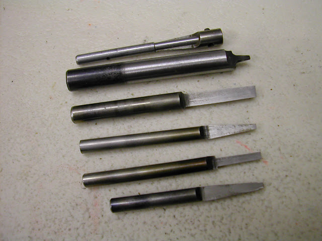
What I do perceive as a 'D bit', and over the years I have made the odd one or two
 is just as previously described ie half diameter form and, where parallel, relieved at the front, with slight back rake. Others of varying form are not relieved and have all performed well in producing the types of hole you wish to achieve ie convex or tapered. is just as previously described ie half diameter form and, where parallel, relieved at the front, with slight back rake. Others of varying form are not relieved and have all performed well in producing the types of hole you wish to achieve ie convex or tapered.This pic is of the 'D bits' made so far for the Bentley BR2. The top one, a reverse counterbore produced 36 tapers in which the headbolts locate. (Material was EN1a) The tapers on the head bolts were turned at the same topslide angular setting as the cutter to ensure a matching fit. It is as sharp as when first produced which was by conventional means - milling and stoning. They are all cut on the centre line and do not have any kind of relief.
 Now I agree that this is forming the hole - scraping if you like - but that's what other than a parallel D bit does and for me it does it well with consistent form and surface finish so this is really to say are you possibly persuing a path that may not need to be tread for the two items you mention.
Of course if your intent is to produce a cutter relieving device per se then I wish you well in your endeavour.
If I can be of further help with that local machine please say.
Regards - Ramon
Edited By Ramon Wilson on 06/05/2011 20:34:10 Edited By Ramon Wilson on 06/05/2011 20:52:43 |
| Clive Hartland | 07/05/2011 10:06:33 |
 2929 forum posts 41 photos | During my work as an engraver which was part of my job description, the engraving cutters were placed in a holder that was then placed on the angled tool holder that went against the wheel.
The holder had a set quadrant that allowed the cutter to be rotated against the wheel.
This gave the cutting edge and the relief required by engaging the wheel and moving it forward into the wheel.
By rotating the holder the rest of the metal behind the relief angle was ground away.
Then the angled tool holder was rotated to a greater than 90 deg position and the tip was moved forward into the wheel to give the tip clearance.
This then gave you a cutter that cut cleanly and depending on the width of the tip grind a thin or wide engraving.
This was all preset on the grinding jig and it also had a holder for two or four lip endmills up to about 6mm. The settings gave the correct clearance once it was in the tool holder.
There was a set of single quadrant and two quadrant and four quadrant discs that were clamped to the end of the tool holder to facilitate the type of cutter being ground.
Once the cutter clearance has been ground, further rotation just took off the un-needed metal behind the lip.
No offset was required for this at all.
Clive |
| Lawrie Alush-Jaggs | 07/05/2011 10:26:49 |
 118 forum posts 32 photos | Hello Evry Bardy I think that what we have established thus far is that everyone’s definition of what constitutes a D bit is based on their experience. 1 Consider an end mill. We have absolutely no problem with the discussion of what constitutes an end mill. Basically it is a cutter derived from the twist drill in which the face can have a profile (flat, ball) which cuts material. In that, its end cutting capacity is similar to the twist drill. The second similarity is in having a helix. Unlike a twist drill though, the edges of the helix are ground to permit machining. 2 Drills. The twist drill and the spoon drill. Both cut at the face. The twist drill really cuts where the spoon drill is not really much more than a rotary waste of time. 3 The Slocum Centre Drill. There were up to the introduction of this tool more than ten styles of device all designed to perform the same operation, none of them anywhere nearly as effectively. The Slocum Centre Drill, which is a derivative of the twist drill won out. In each of these cases we have no dispute as to what name means which tool. The reason I say that this is a taxonomic problem is because the D bit is the only one which is named specifically for its form rather than its function. |
| Lawrie Alush-Jaggs | 07/05/2011 10:32:08 |
118 forum posts 32 photos | Sorry, ran out of space.
Norman: I’m pleased that you are not offended. Thanks. As to the type of grinder……… When I get it made, I shall ask you to name it. So. Can anyone help me with a geometry question?
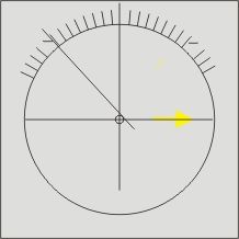 The attached picture is something like what my some described to me. He was very excited that he had come up with a solution as was I. However we haven’t had time to discuss it further so I don’t quite understand how it works other than that it looks as though you make tangential measurements in the X axis relative to the centre of the cam and that as the cam rotates, the centre changes in the Y axis and that if you stick your thumb in the pie, you call out “What a good boy am I” Or Bingo or something. Any takers? |
| Lawrie Alush-Jaggs | 07/05/2011 10:48:47 |
118 forum posts 32 photos | Hi Clive
Thank you for your reply.
"The holder had a set quadrant that allowed the cutter to be rotated against the wheel.
This gave the cutting edge and the relief required by engaging the wheel and moving it forward into the wheel.
By rotating the holder the rest of the metal behind the relief angle was ground away.
Then the angled tool holder was rotated to a greater than 90 deg position and the tip was moved forward into the wheel to give the tip clearance." It is a cam action that provides this. A standard D bit drinder of the type you describe is designed to grind D bits in that it does not provide for greater clearance angles than those which are commonly encountered in engraving. I want to be able to set a wider range of angles so that I can also grind other types of cutters easily like router bits.
This is the reason for the original question.
Lawrie |
| Lawrie Alush-Jaggs | 07/05/2011 10:48:48 |
118 forum posts 32 photos | Hi Clive
Thank you for your reply.
"The holder had a set quadrant that allowed the cutter to be rotated against the wheel.
This gave the cutting edge and the relief required by engaging the wheel and moving it forward into the wheel.
By rotating the holder the rest of the metal behind the relief angle was ground away.
Then the angled tool holder was rotated to a greater than 90 deg position and the tip was moved forward into the wheel to give the tip clearance." It is a cam action that provides this. A standard D bit drinder of the type you describe is designed to grind D bits in that it does not provide for greater clearance angles than those which are commonly encountered in engraving. I want to be able to set a wider range of angles so that I can also grind other types of cutters easily like router bits.
This is the reason for the original question.
Lawrie |
| mgj | 07/05/2011 14:13:31 |
| 1017 forum posts 14 photos | Lawrie - sorry I thought you had a Quorn. To be honest, I reckon your best bet is simply to draw it out with a decent pair of dividers and a protractor at x2 or so. Once you have done that and got sizes into the right parish, I'd put it through Excel and you will get your numbers very easily. Head on you have a fixed radial relationship - its just a matter of getting the cam in the right place. Once you know where your pivot point is you can derive the change in radius at hte points you want to use - work in radians and not degrees and its the back of a fag packet calculation? |
| Lawrie Alush-Jaggs | 07/05/2011 14:24:17 |
118 forum posts 32 photos | Hi MGJ
Thanks for heading back onto the topic. I have to agree with you and had thought that comething like that may have to be the way to do it.
As a Mathmatical numbnuts, what is the difference between radians and degrees and why is it easier to use them?
Thanks, Lawrie |
| Clive Hartland | 07/05/2011 15:16:34 |
2929 forum posts 41 photos | Lawrie, I found that I could get much more cutter relief by just increasing the depth of the engagement with the wheel. The cutting edge clearance was then more pronounced. Basuically I would grind the cutter to the materiel and sometimes it was two or three tries to get a good cutting edge on the specific materiel.
One of the reasons was that when cutting alu. sheet and making templates the alu. would build up on the cutter edge.
Remember that the rpm of the cutter when engraving is in the +20000 range.
Also on some soft materiels I would use a quarter shank cutter because of the extra clearance. No chance of the trailing edge getting fouled up with the chips coming off and if it was plastic it would be very soft and sometimes melt.
The engraving cutter only had a cutting edge at the cone point and if I was cutting out a shape and using a parallell cutter I would then sharpen the whole length of the cutter.
The machine was an Alexander No2 and the Cutter Grinder was a Deckel.
The Talor Hobson cutter grinder was much the same and gave similar results.
Clive |
| Andrew Johnston | 07/05/2011 15:38:57 |
 7061 forum posts 719 photos | Hi Lawrie, The glib answer is that the difference between radians and degrees is a bit over 57. The degree is an arbitrary unit, and a circle contains 360 of them. Each degree is divided into 60 minutes, and each minute is divided into 60 seconds. The radian is an SI derived measure of angle. It is defined as the angle a segment of a circle of radius r subtends when the arc length is also r. A full circle contains 2pi of them. The transcendental functions (sin, cos, tan etc) are naturally expressed in radians and such things as angular velocity are normally expressed in radians per second. To convert from radians to degrees: multiply by 360/2pi To convert from degrees to radians: multiply by 2pi/360 Hope that helps. Regards, Andrew PS: So that means that 1 radian is 360/2pi degrees, which is about 57.3 Edited By Andrew Johnston on 07/05/2011 15:41:05 |
| Nobby | 07/05/2011 19:29:00 |
 587 forum posts 113 photos | Hi This may not help ,but on the chart for the Alexsanders(Decal copy) d bit grinder its says on a 1/4 d bit the fflat should be ten thou plus not on the C/L Nobby |
| Clive Hartland | 07/05/2011 19:44:03 |
2929 forum posts 41 photos | Thats interesting, the cutting edge would then be ground with the lip forward of the centerline ensuring a clearance.
When mounted in the cutter holder to grind the cutter and the quadrant fitted to the holder and located against the stop peg, the lip is presented to the grinding wheel not at right angles to the flat on the cutter, the flat iis sloped back from the face of the wheel and this gives more relief to the cutting lip.
Clive |
| mgj | 07/05/2011 21:17:48 |
| 1017 forum posts 14 photos | Lawrie- a radian isn't just a 2pith of a circle in that sense. Andrew is absolutely right in saying there are 2pi radians in a circle and therfore a rad = whatever it is degrees. I never know and it doesn't matter. Divide 360 by 2pi) The point is that if you know the distance at the circumference that you are rotating through then distance at circumference/radius = angular rotation in radians. Convert for scale in degrees. Multiply or divide by 2pi and you are moving from rads to deg and vice versa with ease, and its so easy to get the angle in rads because you can relate it directly to distance. (but see note below) So if you need so much relief in mm or decimals thereof, and you know diameter, you barely need to take your socks off to calculate an answer in degrees, because you are not using an arbitrary unit of angular measure any longer, but the relationship of circumference to radius. Its not a thing used much in non engineerlng applications, but its the standard unit for using in calculations involving rotation, angular momentum etc, so a lot of people won't have met it, but its very easy, and 5 mins with a calculator for practise and you can get distances and angles with ease. Then you can mount your eccentric non eccentrically in the dividing head and mark away in degrees. Obviously the amount of relief applied will vary with diameter for a given angular measure so you'll need a little chart to relate degrees to amount of relief per unit diameter. But with 2pi at your side thats a 2 second calculation. Thankyou Pythagoras - did he discover pi or first calculate it or somesuch? Think so, but could well be wrong. (there is an error in my statement above because I am actually using a chord and not an arc, but for small proportions of the circumference it wont matter.) Edited By mgj on 07/05/2011 21:32:11 |
| Lawrie Alush-Jaggs | 08/05/2011 12:54:48 |
118 forum posts 32 photos | Hi Everyone Thank you all for your replies. Clive: Thanks. The workshop in which I did engraving had six Deckel 2D's a Deckel 2 1/2 D, two Alexanders and a Dahlgren computer driven machine. We didn't much use the Alexander as although it was a copy of the Deckel it was just not as good. The bearings were not as smooth and the lapping on the spindle was not quite as accurate. That may have been down to age or just that we all seemed to prefer the Deckels. We had two Deckel grinders. I understand what you are saying about different materials but in this case my problem is not about the end to which the cutters will be put, rather an aspect of the machine used to produce them. MGJ: Thanks for your lucid answers. As you say, some time spent with a calculator should get things right. "Obviously the amount of relief applied will vary with diameter for a given angular measure so you''ll need a little chart to relate degrees to amount of relief per unit diameter." I don't understand why the angle should change with the diameter of the cutter. The selection of angle does not take place with the cutter at 90 deg to the wheel or as shown in the illustrations. Instead the collet is loosened, the cutter rotated through 180 degrees, tighten the collet and then select the angle. So as far as the ground face of the cutter is concerned, the eccentric is moved relative to the verticle rather than the horizontal. Once the setting is done, the collet is rotated back through ninety degrees and you start grinding your clearance angle. I may have the sequence slight out of step, it is twenty five years since I used a D bit grinder but the principle is correct. I've sent a crate of whisky to Pythagoras. Nobby: Thanks for your response Nobby. I understand what you are saying but as in my reply to Clive, I am not so much interested in a cutter/bit at present as the relationship between the position of the cutter in the grinder and the alignment marks used to determine just how much clearance there is on the cutter. Lawrie
|
| Gordon W | 08/05/2011 15:58:37 |
| 2011 forum posts | My brain hurts, and I am supposed to be quite good at maths. Surely a D bit is so called because the cross -section is a D shape? If a clearance angle is ground on then it will not be D shaped, so not a D bit? Just for further confusion I always thought of a D bit as being made from round bar, with a long flat ground on from the tip at an angle, so only one section will be a D. Make good reamers tho. |
| Tony Jeffree | 08/05/2011 18:35:31 |
 569 forum posts 20 photos | Posted by Steve Garnett on 05/05/2011 17:55:38: I've got the ultimate grinder for you, Norman - it's a Steworndent! I would have thought a Squorn would be more appropriate  Regards, Tony |
| mgj | 08/05/2011 18:39:15 |
| 1017 forum posts 14 photos | Alex its not the angle which changes with dia - you are going to set an angle, but the amount in thou taken off - the curved wedge will increase with dia, for a given angle - look at your drawing head on. My brain is fading, but that may be from the Chaddock/Quorn approach, which I am more familiar with, and I was assuming similar geometry. Only one way to find out - draw it up and check. Sorry, but you'll do the rithmetic easy enough, so I bow out! Wishing you luck with the compasses!. |
Please login to post a reply.
Magazine Locator
Want the latest issue of Model Engineer or Model Engineers' Workshop? Use our magazine locator links to find your nearest stockist!
Sign up to our Newsletter
Sign up to our newsletter and get a free digital issue.
You can unsubscribe at anytime. View our privacy policy at www.mortons.co.uk/privacy
Latest Forum Posts
- *Oct 2023: FORUM MIGRATION TIMELINE*
05/10/2023 07:57:11 - Making ER11 collet chuck
05/10/2023 07:56:24 - What did you do today? 2023
05/10/2023 07:25:01 - Orrery
05/10/2023 06:00:41 - Wera hand-tools
05/10/2023 05:47:07 - New member
05/10/2023 04:40:11 - Problems with external pot on at1 vfd
05/10/2023 00:06:32 - Drain plug
04/10/2023 23:36:17 - digi phase converter for 10 machines.....
04/10/2023 23:13:48 - Winter Storage Of Locomotives
04/10/2023 21:02:11 - More Latest Posts...
- View All Topics
Support Our Partners


Shopping Partners
Subscription Offer

Latest "For Sale" Ads
- Reeves** - Rebuilt Royal Scot by Martin Evans
by John Broughton
£300.00 - BRITANNIA 5" GAUGE James Perrier
by Jon Seabright 1
£2,500.00 - Drill Grinder - for restoration
by Nigel Graham 2
£0.00 - WARCO WM18 MILLING MACHINE
by Alex Chudley
£1,200.00 - MYFORD SUPER 7 LATHE
by Alex Chudley
£2,000.00 - More "For Sale" Ads...
Latest "Wanted" Ads
- D1-3 backplate
by Michael Horley
Price Not Specified - fixed steady for a Colchester bantam mark1 800
by George Jervis
Price Not Specified - lbsc pansy
by JACK SIDEBOTHAM
Price Not Specified - Pratt Burnerd multifit chuck key.
by Tim Riome
Price Not Specified - BANDSAW BLADE WELDER
by HUGH
Price Not Specified - More "Wanted" Ads...
Get In Touch!
Do you want to contact the Model Engineer and Model Engineers' Workshop team?
You can contact us by phone, mail or email about the magazines including becoming a contributor, submitting reader's letters or making queries about articles. You can also get in touch about this website, advertising or other general issues.
Click THIS LINK for full contact details.
For subscription issues please see THIS LINK.
Digital Back Issues


Donate

 Register
 Log-in
Model Engineer Magazine
- Percival Marshall
- M.E. History
- LittleLEC
- M.E. Clock

ME Workshop
- An Adcock
- & Shipley
- Horizontal
- Mill

Subscribe Now
- Great savings
- Delivered to your door

Pre-order your copy!
- Delivered to your doorstep!
- Free UK delivery!
All Forum Topics > Workshop Tools and Tooling > D bit grinder work head calculations