Forum sponsored by:

turning a large diameter
39" radius
| Bazyle | 05/09/2023 11:06:14 |
 6956 forum posts 229 photos | Posted by JasonB on 05/09/2023 10:14:24:
PS Younger guys will give an answer before 7.00am You mean before going to bed after they get back from clubbing? BTW this 'long radius' thing is common model engineer practice making expansion links on steam engines. Edited By Bazyle on 05/09/2023 11:08:23 |
| Grindstone Cowboy | 05/09/2023 11:12:03 |
| 1160 forum posts 73 photos | Yes but there is a good chance that alot of them will have woken up grumpy lol
Pete But some of them might let their wives to sleep late I'll get me coat... Rob |
| bernard towers | 05/09/2023 12:02:33 |
| 1221 forum posts 161 photos | Its 39" RAD chaps |
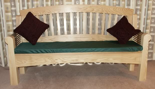
| JasonB | 05/09/2023 12:23:56 |
 25215 forum posts 3105 photos 1 articles | 39" makes no real difference to the method I showed, might just need to extend the pivot point out beyond the R?H end of the lathe but that is simple enough.
All the curves on this bench I made were done in a similar sort of way and radiate out from a single point, from memory the top of the rear rail is 6.5m radius
|
| DC31k | 05/09/2023 12:35:20 |
| 1186 forum posts 11 photos | OK, it is not turning and it will not produce a circular arc, but you would get very close with a boring head in a mill and angling the head of the mill. When the head is perpendicular to the table, it produces an infinite radius (flat surface). When it is parallel to the table, it produces a circular radius equal to the swept diameter of the cutter. So at some angle between those two it will produce an elliptical arc which will be very close to the 39" circular radius needed. Replace the single point tool of the boring head with an abrasive wheel and the ground finish becomes a possibility. --- There is also the method used in woodworking of calculating the sagitta of the arc, nailing two straight pieces together at an angle and swinging them between the two end points of the chord. The vertex sweeps out the arc. |
| david bennett 8 | 05/09/2023 13:27:44 |
| 245 forum posts 19 photos | Thanks for all the ideas. Perhaps you now understand the lack of dimensions. This is for a clock pendulum suspension, and needs to be accurate. I am leaning towards making this of two identical pieces of, say, 2mm thick steel plate. The only critical dimension is the radius and the need for the rolling edge to be at 90 degrees to the faces. I am hoping to avoid hand working the rolling faces to preserve accuracy. If I had the choice of machines, Ithink I would be looking at a pantograph engaving machine. dave8 Edited By david bennett 8 on 05/09/2023 13:29:58 Edited By david bennett 8 on 05/09/2023 13:44:12 |
| JasonB | 05/09/2023 13:32:46 |
25215 forum posts 3105 photos 1 articles | It will be as accurate as you make it. As Bazyle says the method I describe is commonly used to make parts of the valve gear on locos and traction engines 0.025mm or 0.001" accuracy is quite possible. Though you will need the equipment to measure 39" to the accuracy you feel you need. Edited By JasonB on 05/09/2023 13:39:49 |
| Mick B1 | 05/09/2023 14:13:11 |
| 2444 forum posts 139 photos | You could try trepanning it out of a piece of flat bar - that's what I did with the traverse truck for a model carronade I was making:-
But the radius was far smaller than the one you're trying to do. I'd reckon you'd gotta work on the biggest lathe, and do some o' the baddest things... |
| John Haine | 05/09/2023 15:10:12 |
| 5563 forum posts 322 photos | I thought I'd try generating it in CamBam for CNC milling.
Assuming it would be milled from 2mm plate, the top shows the plan view and the bottom the toolpaths including 6 holding tabs, using a 3mm endmill. These not positioned on the "active" top left face as they have to be filed away after cutting. You can just about see that this face is slightly curved. Though designed initially "flat", I rotated the design to avoid one of the axes having to reverse while cutting the curve which inevitably leaves a tiny mark due to even the smallest backlash. |
| david bennett 8 | 05/09/2023 20:44:17 |
| 245 forum posts 19 photos | Jason, thanks for that. dave8
|
| david bennett 8 | 05/09/2023 20:52:52 |
| 245 forum posts 19 photos | Posted by John Haine on 05/09/2023 08:33:01:
Cnc mill the profile. Polish by hand. Actually 1 metre approx outside diameter. Thanks for the correction - I think I was suffering from a thick brain. dave8 |
| JasonB | 06/09/2023 07:00:58 |
25215 forum posts 3105 photos 1 articles | So what is it, 1m OD (500mm Radius) or the 39" (990.6mm) Radius or 1m radius (1000mm) |
| John Haine | 06/09/2023 07:22:20 |
| 5563 forum posts 322 photos | 500mm radius. |
| KWIL | 06/09/2023 08:56:18 |
| 3681 forum posts 70 photos | Use DRO . radius is set by X = required radius. X=0 can be anywhere you want off the end of the table. Input Xrad Set cutter diameter and cut on outside, use small incremental steps for Y. When done merely smooth rouugh edge to take off peaks. |
| bernard towers | 06/09/2023 09:06:29 |
| 1221 forum posts 161 photos | First post says 39" rad |
| Michael Gilligan | 06/09/2023 09:08:25 |
 23121 forum posts 1360 photos | Posted by bernard towers on 06/09/2023 09:06:29:
First post says 39" rad . And subsequent posts have corrected that ^^^ MichaelG. |
| JasonB | 06/09/2023 10:00:00 |
25215 forum posts 3105 photos 1 articles | DRO Is OK if you have a mill but the OP says he only has a Myford and he also says he does not want to hand finish. Ditto CNC which would breeze through a simple part but again he does not have one. But still no consensus on what radius/diameter is wanted. |
| Michael Gilligan | 06/09/2023 10:50:52 |
23121 forum posts 1360 photos | Posted by JasonB on 06/09/2023 10:00:00:
[…] But still no consensus on what radius/diameter is wanted. . I think we can take Mr Haine’s statement as authoritative MichaelG. . see post by dave8 05/09/2023 20:52:52 Edited By Michael Gilligan on 06/09/2023 10:53:53 |
| JasonB | 06/09/2023 12:18:05 |
25215 forum posts 3105 photos 1 articles | So is that the Approx 1m dia or the 500mm (no tolerance) radius for this accurate job |
| Michael Gilligan | 06/09/2023 12:51:26 |
23121 forum posts 1360 photos | Posted by JasonB on 06/09/2023 12:18:05:
So is that the Approx 1m dia or the 500mm (no tolerance) radius for this accurate job . With regard the manufacturing process [which was the essence of the opening question] … I suspect it matters something less than 2/3 of b***** all. MichaelG. |


Please login to post a reply.
Magazine Locator
Want the latest issue of Model Engineer or Model Engineers' Workshop? Use our magazine locator links to find your nearest stockist!
Sign up to our Newsletter
Sign up to our newsletter and get a free digital issue.
You can unsubscribe at anytime. View our privacy policy at www.mortons.co.uk/privacy
Latest Forum Posts
- *Oct 2023: FORUM MIGRATION TIMELINE*
05/10/2023 07:57:11 - Making ER11 collet chuck
05/10/2023 07:56:24 - What did you do today? 2023
05/10/2023 07:25:01 - Orrery
05/10/2023 06:00:41 - Wera hand-tools
05/10/2023 05:47:07 - New member
05/10/2023 04:40:11 - Problems with external pot on at1 vfd
05/10/2023 00:06:32 - Drain plug
04/10/2023 23:36:17 - digi phase converter for 10 machines.....
04/10/2023 23:13:48 - Winter Storage Of Locomotives
04/10/2023 21:02:11 - More Latest Posts...
- View All Topics
Support Our Partners


Shopping Partners
Subscription Offer

Latest "For Sale" Ads
- Reeves** - Rebuilt Royal Scot by Martin Evans
by John Broughton
£300.00 - BRITANNIA 5" GAUGE James Perrier
by Jon Seabright 1
£2,500.00 - Drill Grinder - for restoration
by Nigel Graham 2
£0.00 - WARCO WM18 MILLING MACHINE
by Alex Chudley
£1,200.00 - MYFORD SUPER 7 LATHE
by Alex Chudley
£2,000.00 - More "For Sale" Ads...
Latest "Wanted" Ads
- D1-3 backplate
by Michael Horley
Price Not Specified - fixed steady for a Colchester bantam mark1 800
by George Jervis
Price Not Specified - lbsc pansy
by JACK SIDEBOTHAM
Price Not Specified - Pratt Burnerd multifit chuck key.
by Tim Riome
Price Not Specified - BANDSAW BLADE WELDER
by HUGH
Price Not Specified - More "Wanted" Ads...
Get In Touch!
Do you want to contact the Model Engineer and Model Engineers' Workshop team?
You can contact us by phone, mail or email about the magazines including becoming a contributor, submitting reader's letters or making queries about articles. You can also get in touch about this website, advertising or other general issues.
Click THIS LINK for full contact details.
For subscription issues please see THIS LINK.
Digital Back Issues


Donate

 Register
 Log-in
Model Engineer Magazine
- Percival Marshall
- M.E. History
- LittleLEC
- M.E. Clock

ME Workshop
- An Adcock
- & Shipley
- Horizontal
- Mill

Subscribe Now
- Great savings
- Delivered to your door

Pre-order your copy!
- Delivered to your doorstep!
- Free UK delivery!
All Forum Topics > General Questions > turning a large diameter