Forum sponsored by:

CHUKY Flame Licker Build
| JasonB | 27/10/2017 20:19:15 |
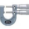
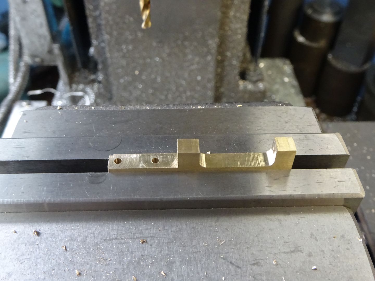
 25215 forum posts 3105 photos 1 articles | Shutter parts Shutter Rod Guide I did not have any 5mm thick brass so thinned down the end of a piece of 1/4" material and then drilled the 2.0mm hole at least 31mm deep.
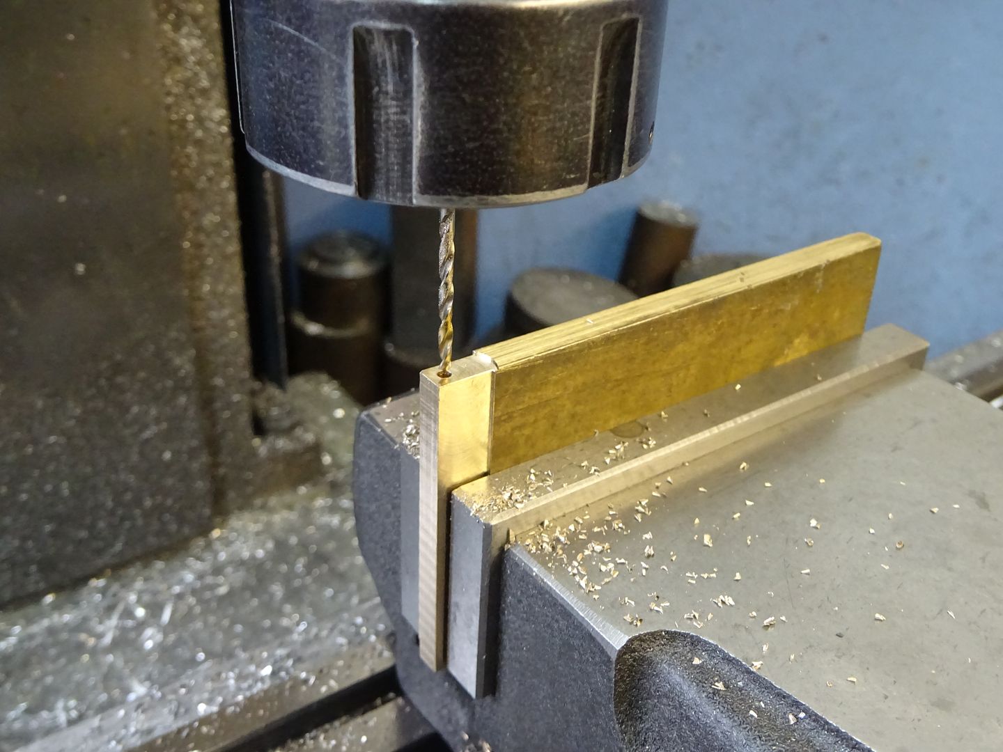
With the work now on it's side the recess was milled out with a 6.0mm cutter to give the required 3.0mm radius to the internal corners.
After cutting off from the parent bar the back face is milled to finished size and then the 1.0mm step cut from the lower end.
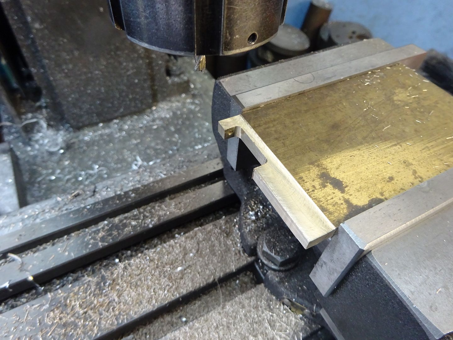
Turning the part the other way up the larger recess can be milled out, the two 2.0mm holes drilled and then countersunk then finish off by filing the 2.5mm radius around the upper screw hole.
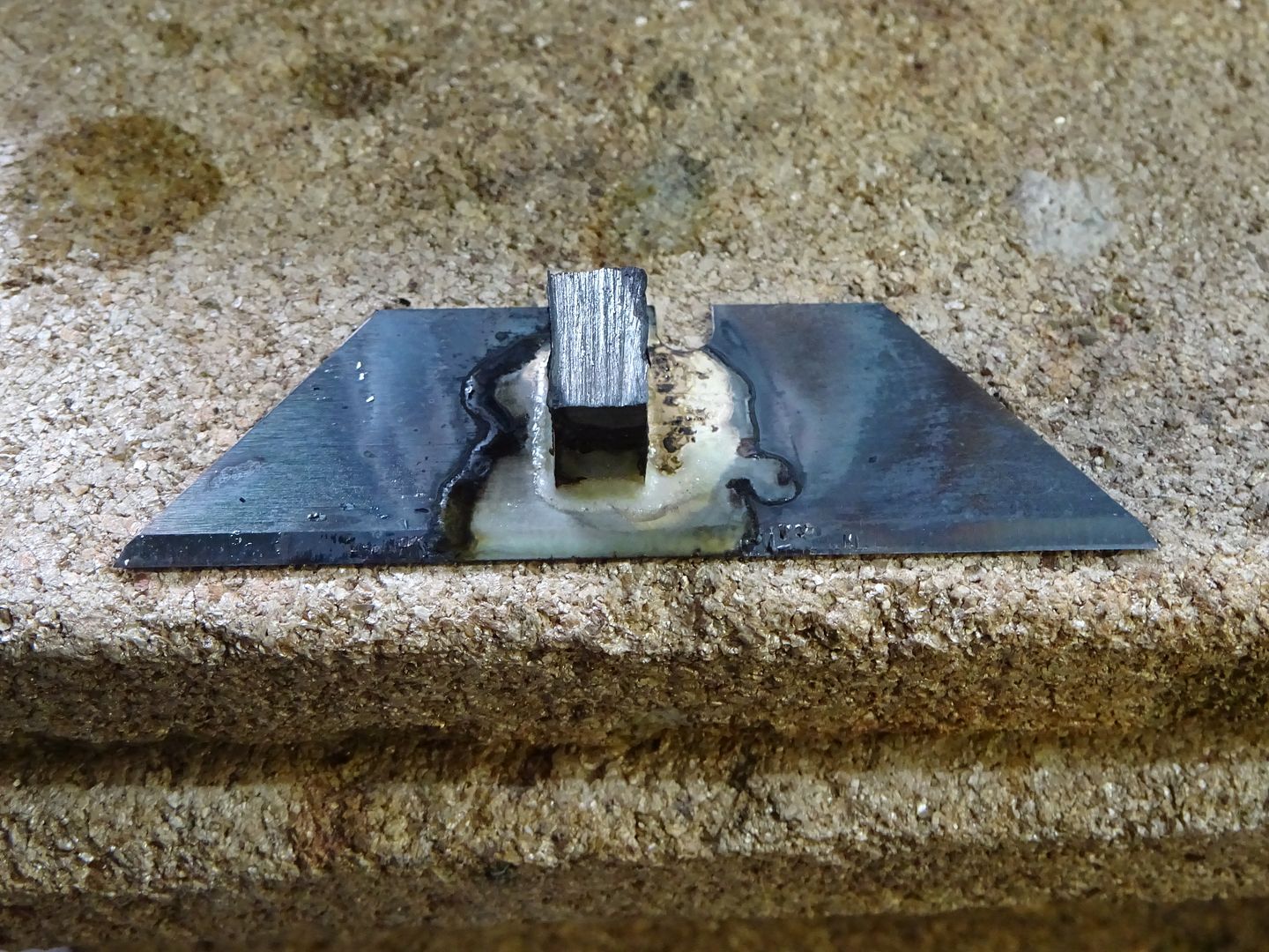
This starts life as a Stanley knife blade or "utility" knife as I think our American members call them. It is best to shape the knife blade after the steel block has been soldered on just in case it moves about during silver soldering. Also worth leaving te block a bit long to start with so just make teh 5x8 dims to finished size then solder.
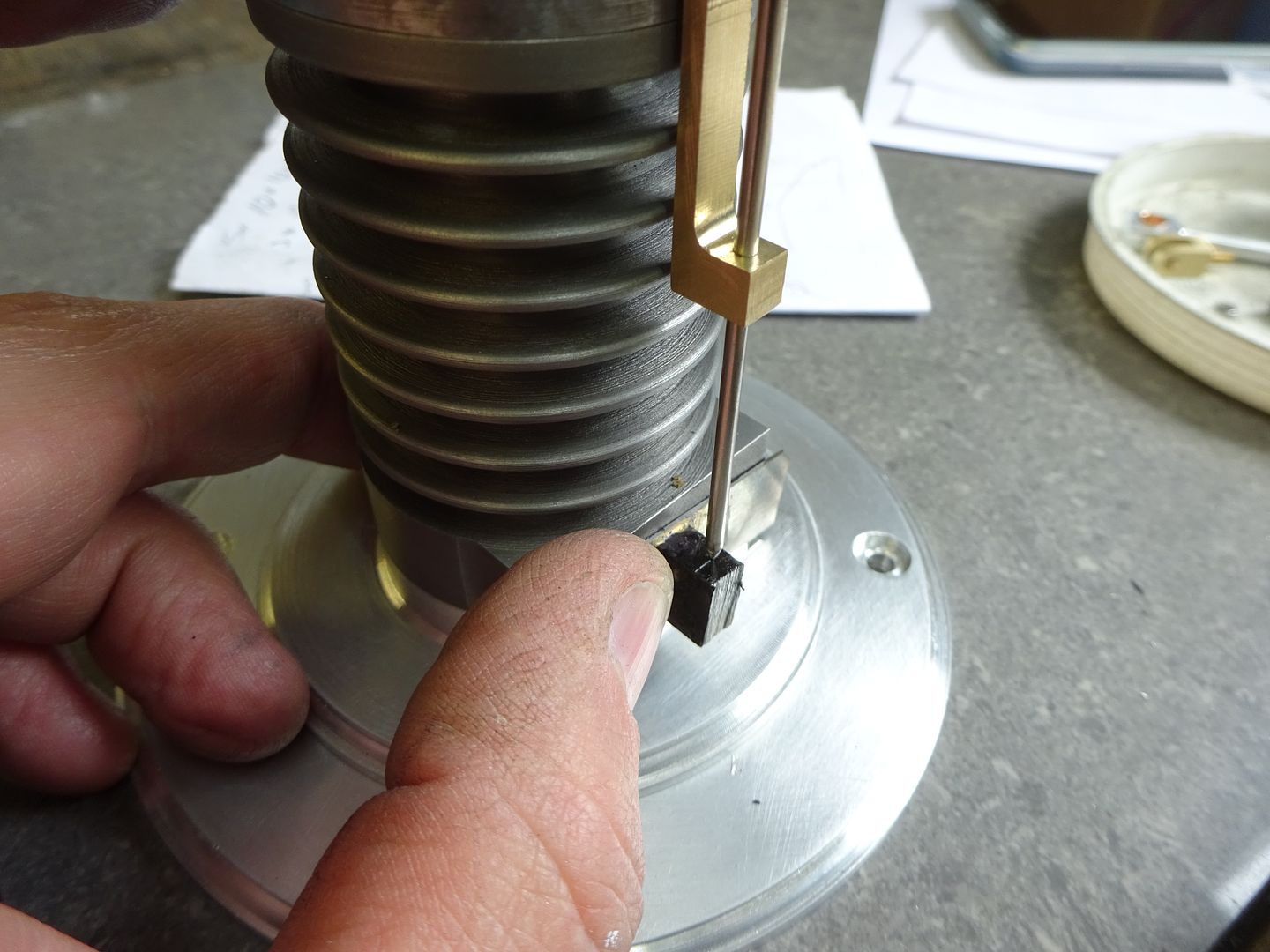
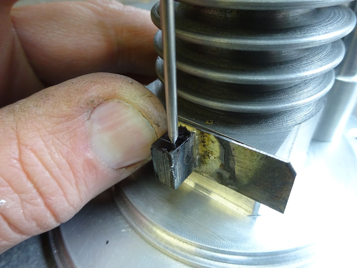
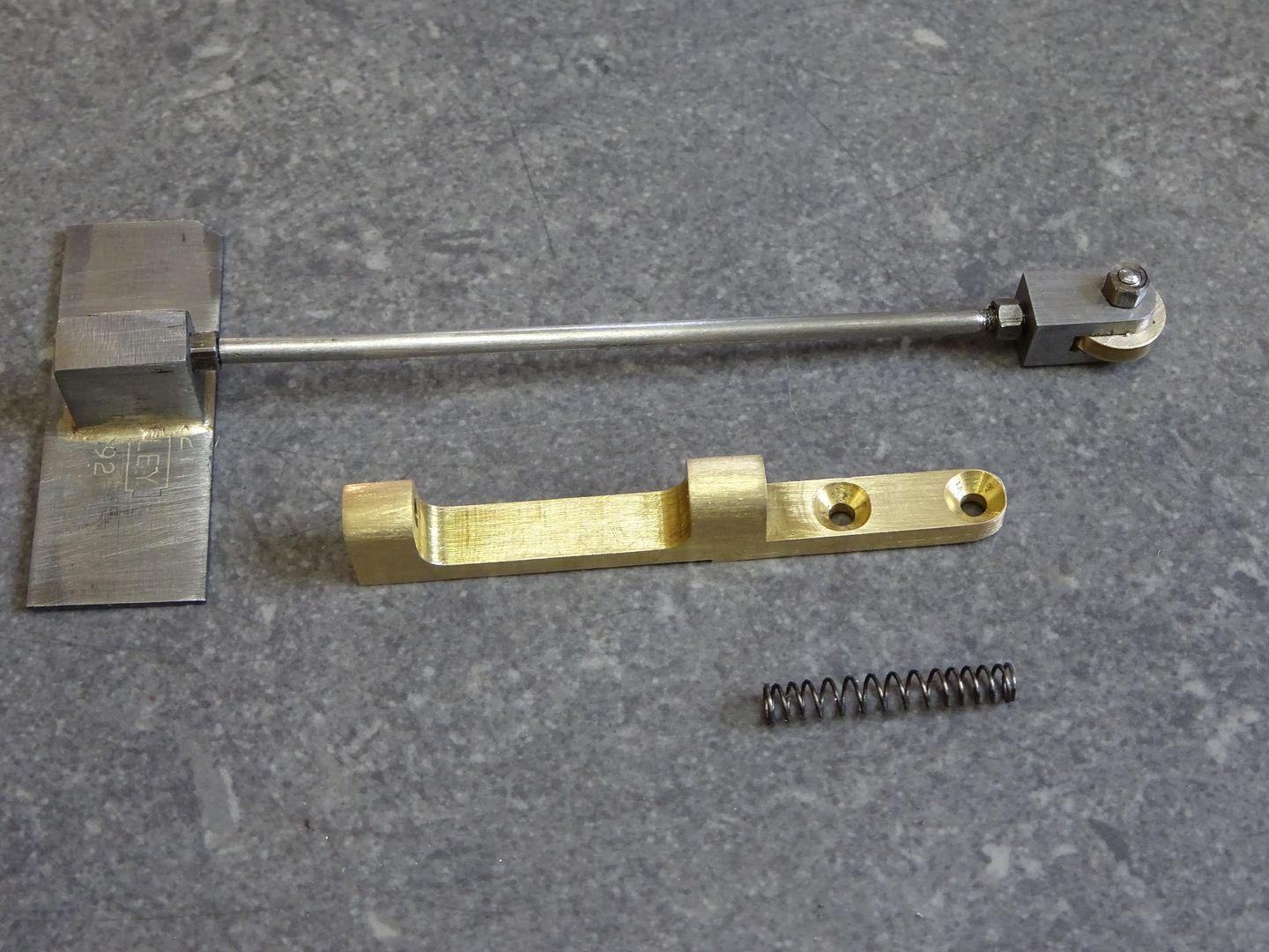
The blade can then be roughly trimmed to size making sure the edges are true to the edges of the block. With the rod guide screwed into place machine a point onto some 2.0mm rod and pass that through the guide and use the rod as a scriber to mark the position of the M2 hole.
The hole can now be drilled and then tapped M2 and the block rounded over. I would suggest leaving the final shaping of the shutter until it is mounted on it's rod. Shutter Rod This is quite a simple job so no photos, face the rod to length and cut the M2 thread on each end to the lengths required. This shot shows the finished part , the fork and cam follower roller will be covered next time.
J |
| Raymond Sanderson 2 | 01/01/2018 04:54:18 |
 450 forum posts 127 photos | Thanks Jason been a while since pocking my head over the fence but I have been peering through if you get my drift.
Ray |
| JasonB | 01/01/2018 07:05:48 |
25215 forum posts 3105 photos 1 articles | Very Little, I'll try and get it up in the next few days |
| SillyOldDuffer | 01/01/2018 17:34:55 |
| 10668 forum posts 2415 photos | I've got this one firmly on my to do list. All I need to do is work faster on my existing backlog. Much faster... Dave |
| JasonB | 01/01/2018 19:10:28 |
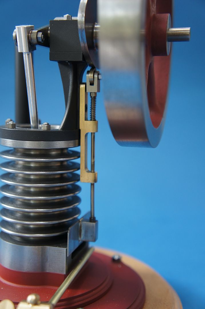
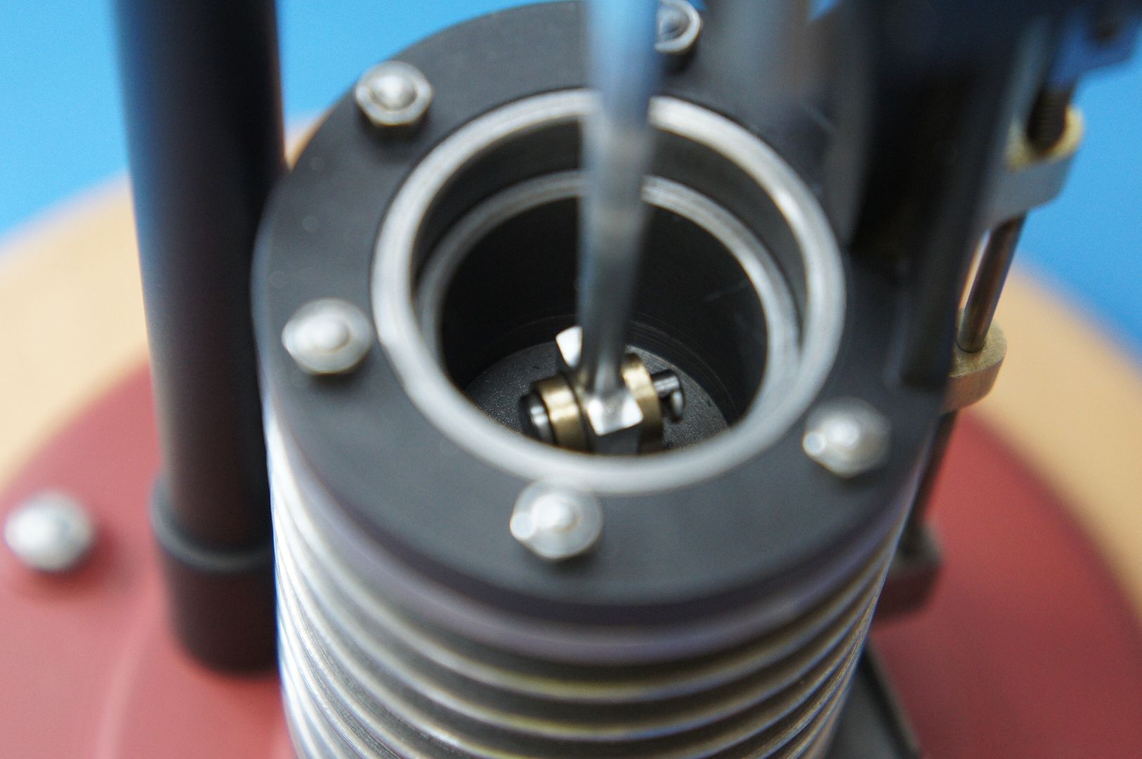
25215 forum posts 3105 photos 1 articles | Back by popular demand! Cam Follower and Valve Cam Follower A simple turning job from brass, face off, drill 2.0mm and part off to 2.0mm thick Cam Follower Fork I did not have any 5mm square stock so milled down the end of a round bar and while in the indexer drilled and countersunk the 2.0mm hole then rotated it 90degrees and used a slitting saw to form the slot. Then into the lathe to drill 1.6mm and tap M2 before parting off to length. Cam Follower pin Another simple turning job, make sure the head is small enough to fit just below the surface of the Follower Fork. You will also need a small dia spring to slip over the valve rod, about 20mm free length, 0.5mm wire. Does not need to be too strong as that will increase the load on the engine - just enough to keep the follower in contact with the cam
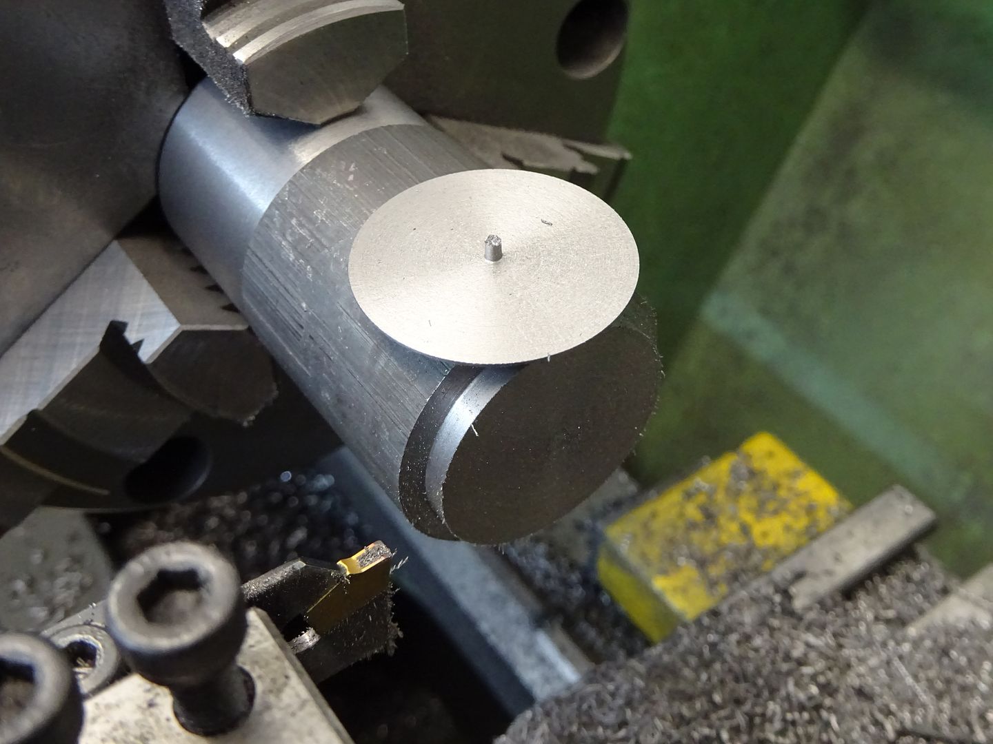
Valve Face off the end of a piece of cast iron , turn OD down to 28.0mm and then part off a 0.5mm thick slice, if your parting tool leaves a pip in the middle don't remove it.
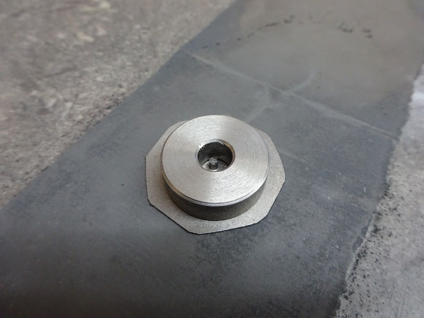
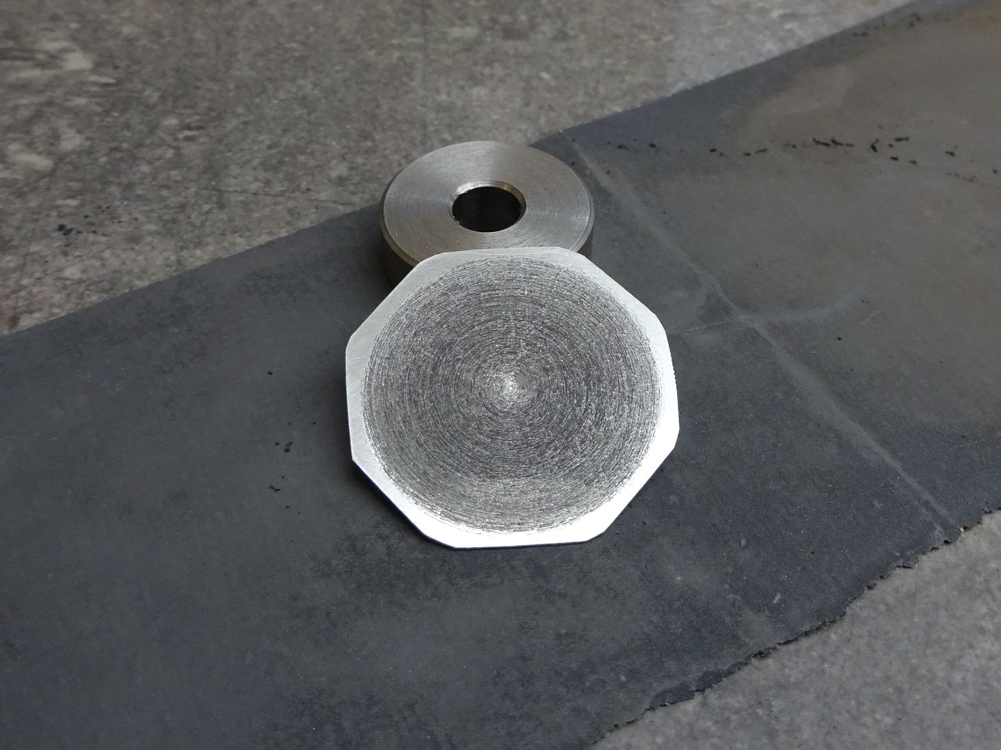
The eight sides that form the octagon can just be filed but make sure you leave a small part of the 28.0mm dia edge between each as it will help keep the valve centred within the base. The valve can then be lapped on some 1200g wet & dry using a disc of metal to keep it flat, this is where the pip helps.
Parting off will leave the valve slightly concave so you only need to lap the edge as can be seen by the polished area
Just the flywheel and burner parts left to deal with J |
| Ian S C | 02/01/2018 11:28:31 |
 7468 forum posts 230 photos | I'v been using slivers of cast iron, lapped to the valve face, for shutters, do the craft knife blades not tend to warp when they are silver soldered. My latest source of cast iron is the bed of an old sewing machine. Ian S C |
| Pero | 03/01/2018 03:26:20 |
| 193 forum posts | Hello Jason First of all thank you for going to the effort of getting the engine plans and description up on the website. A little engine but not a little effort! Ian asked the first of my questions on the use of Stanley knife blades for the shutter - that of possible warping when silver soldering. My other question is whether corrosion following silver soldering or in use is a problem. I have managed over the years to cause extreme rust on the blades without them ever being exposed to heat. Is there some method of preventing this when the blade is used as a shutter? I have another flame licker design that I am working on and am interested in the use of various key materials in their construction, the shutter being one of these. Thanks Pero
|
| JasonB | 03/01/2018 07:13:28 |
25215 forum posts 3105 photos 1 articles | I did not notice any warping after soldering and he face that goes against the port cleaned up all over very quickly when rubbed on some fine wet and dry. Looking at the shutter now there is no sign of rust, there is a bit of soot on it but that rubs off with a finger and nor rust below. It does not have to be a knife blade or a carbon steel, the blade is just an easy source of flat thin material, if you have flat shim that would also do. Same with the valve Graham Corry told me yesterday that he has used the bottom of a "Pringles" tube for that on several engines. |
| Ian S C | 03/01/2018 10:15:30 |
7468 forum posts 230 photos | Thanks Jason, I'm just following at the moment, but I really must get going on something. Ian S C |
| JasonB | 04/01/2018 18:48:46 |
25215 forum posts 3105 photos 1 articles | Burner Support Base A simple turning job, face off the end of a piece of 10mm dia brass, use a small round nosed tool to add the decorative moulding, drill 3.0mm and part off to 2.0mm thick Burner Clamp Face off the same bit of 10mm brass and then over to the mill to cross drill the 5.0mm and 3.125mm (1/8" Burner post Form a decorative end on a piece of 5.0mm dia brass which can be done with a form tool of freehand and then refined with a file. Part off to length, reverse in chuck and drill and tap the bottom M3 Burner Thumb Screw reduce the end of an 8mm piece of brass down to 3.0mm and therad M3. Then form an oval end again with a form tool or freehand. Over to the mill and cut 2.5mm off each side. J Edited By JasonB on 04/01/2018 19:20:30 |
| JasonB | 04/01/2018 19:26:34 |
25215 forum posts 3105 photos 1 articles | Burner Tube and Flywheel Burner Tube This is silver soldered together from the three parts shown. The main tube has five holes drilled 0.5mm dia at a spacing of 4.0mm starting 5.0mm in from one end. This end has a small plug soldered into it which can be turned or a brass rivit can be used. The other end will depend on the gas hose that you have. Mine needed a hole to take a 6mm O ring seal and threading M7 x 0.75 for the union.
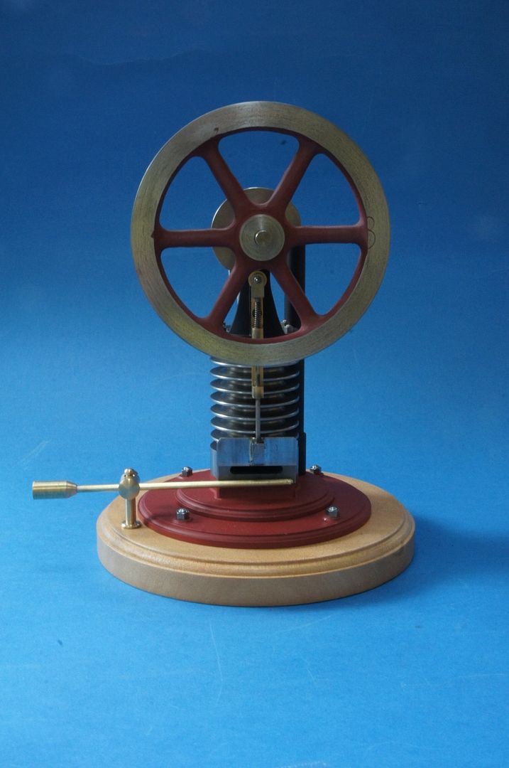
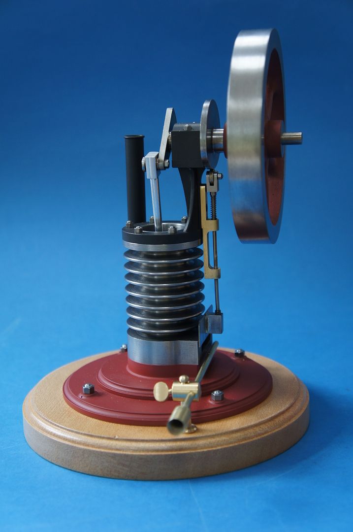
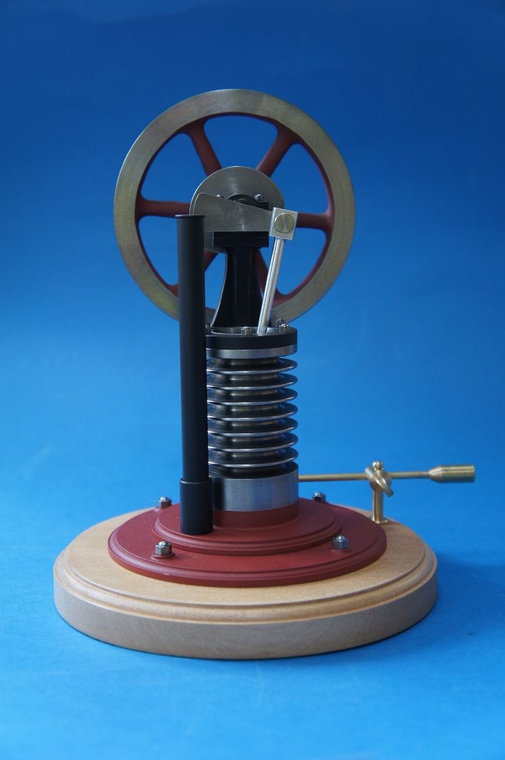
Flywheel Flywheel I chose to use a casting but you could also machine one from solid. There are several suitable sized flywheels about this one came from Reeves and is their Perseus one, RDG do a part machined one and there are a couple of e-bay sellers that have flywheels too. Final dia and width of rim are not critical so just machine off enough to clean up the surfaces as any extra weight will help with smooth running If you have a small enough boring bar then use that to take the bore to final size from say a 5.5mm drilled hole if not drill and ream. Add a M3 cross hole for a grub screw to retain the flywheel.
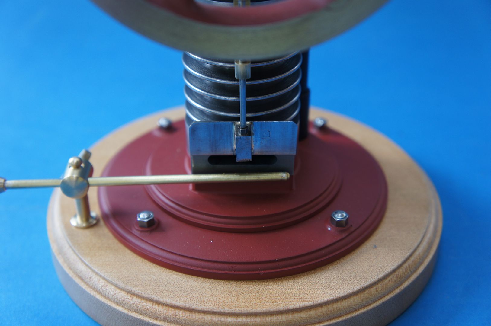
Well that's about it as far as construction goes. The cam should be adjusted so that the intake port is just starting to open as the crank pin reaches the 5 o'clock position when viewed from the shutter side and should be closed at about 11 o'clock. If all is right the engine will turn easily in the clockwise direction and make the farting noise as the piston descends but if turned over anti clockwise should be quite hard to turn as the piston comes up. Correct running rotation is clockwise when viewed from the shutter side. Once the flame is lit the engine will need flicking over a few times to warm it up and will slowly start to run for a bit longer after each flick until it reaches a point where it will continue to run. You may have to play about with flame position to find the sweet spot and position can also be used to alter speed as can size of flame. The bearings and big & little ends can have a small amount of light oil but the piston can be run dry or if you feel the need apply a little WD40 (not while flame lit!) I use a couple of colours of stove paint on the engine which does get hot so whatever you use should be heat resistant. A round wooden base can also be easily made on the lathe and gives somewhere to screw the burner support.
J |
| David George 1 | 06/01/2018 09:24:08 |
 2110 forum posts 565 photos | Hi Jason nice project I am just starting to make parts but where did you get the gas regulator and hose from. It would help as I can't see it at local supliers. David |
| JasonB | 06/01/2018 10:18:06 |
25215 forum posts 3105 photos 1 articles | David, I bought a cheap camping stove from E-bay as I thought it may come in handy but you can also get the hose & regulator seperately. The Thread is M7 x 0.75 and I got the taps from Rotagrip, just their basic HSS ones not a named brand as I can't see me using them very often. |
| Ian S C | 07/01/2018 10:12:14 |
7468 forum posts 230 photos | I make a habbit of buying or obtaining camp stoves for the burners, taps, and hoses for hot air engines. Ian S C |
| Raymond Sanderson 2 | 13/01/2018 03:51:13 |
450 forum posts 127 photos | Jason many thanks when I get time I'll come back and go over the new posts. |
| jimmy b | 13/01/2018 05:48:38 |
 857 forum posts 45 photos | Very nice!
Jim |
| Ron Laden | 07/12/2020 10:31:31 |
 2320 forum posts 452 photos | Hi Jason From memory I think the Perseus 4 inch flywheel casting is the one used on the Jowett. I do have a spare wheel that's used on the Muncaster (bought two) but I guess it may just look a bit big at 4.5/8" what do you think..? Ron |
| JasonB | 07/12/2020 11:52:33 |
25215 forum posts 3105 photos 1 articles | You might just get away with it Ron, The Muncaster one could go down to 108mm dia and 13-14mm wide which would mean it doe snot end up looking too heavy for the engine. |
| Ron Laden | 14/12/2020 09:20:27 |
2320 forum posts 452 photos | Morning Jason, I am putting together a shopping list as my metals stock is running low, so I thought it made sense to add whats needed for the CHUKY. I printed off a set of drawings and the BOM plus have read through your build guide and am happy with all of that, the drawings and guide are excellent as usual. The only thing I am going to try is to get by with no silver soldering, I am still not really geared up for it, I know, I know I should be by now but I,m not. I thought I would try and machine the shutter as a one piece from some flat bright steel bar I have. The bearing support I thought a turned base ring and a part turned/part milled upstand (shape may be slightly different) and a rectangular top pad all of which fixed together with small loctited csk screws. I will also use the Muncaster wheel and take it down to 108mm as you suggest. Looking forward to it. Ron
|
| JasonB | 14/12/2020 10:31:42 |
25215 forum posts 3105 photos 1 articles | You might get away with a screwed together shutter, if you used say 1mm thick steel and a small CSK screw into a block that may just do it. Cutting from solid would risk the thin section bending but it could be lapped back flat. J |
 holes at right angles to each other. Back into the lathe and drill and tap the M3 hole before parting off.
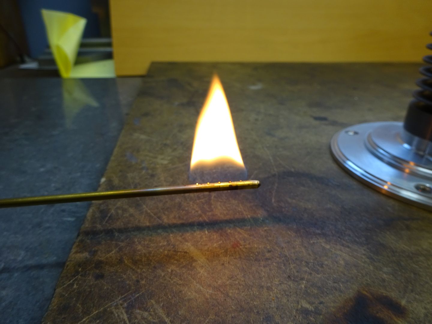
Please login to post a reply.
Magazine Locator
Want the latest issue of Model Engineer or Model Engineers' Workshop? Use our magazine locator links to find your nearest stockist!
Sign up to our Newsletter
Sign up to our newsletter and get a free digital issue.
You can unsubscribe at anytime. View our privacy policy at www.mortons.co.uk/privacy
Latest Forum Posts
- *Oct 2023: FORUM MIGRATION TIMELINE*
05/10/2023 07:57:11 - Making ER11 collet chuck
05/10/2023 07:56:24 - What did you do today? 2023
05/10/2023 07:25:01 - Orrery
05/10/2023 06:00:41 - Wera hand-tools
05/10/2023 05:47:07 - New member
05/10/2023 04:40:11 - Problems with external pot on at1 vfd
05/10/2023 00:06:32 - Drain plug
04/10/2023 23:36:17 - digi phase converter for 10 machines.....
04/10/2023 23:13:48 - Winter Storage Of Locomotives
04/10/2023 21:02:11 - More Latest Posts...
- View All Topics
Support Our Partners


Shopping Partners
Subscription Offer

Latest "For Sale" Ads
- Reeves** - Rebuilt Royal Scot by Martin Evans
by John Broughton
£300.00 - BRITANNIA 5" GAUGE James Perrier
by Jon Seabright 1
£2,500.00 - Drill Grinder - for restoration
by Nigel Graham 2
£0.00 - WARCO WM18 MILLING MACHINE
by Alex Chudley
£1,200.00 - MYFORD SUPER 7 LATHE
by Alex Chudley
£2,000.00 - More "For Sale" Ads...
Latest "Wanted" Ads
- D1-3 backplate
by Michael Horley
Price Not Specified - fixed steady for a Colchester bantam mark1 800
by George Jervis
Price Not Specified - lbsc pansy
by JACK SIDEBOTHAM
Price Not Specified - Pratt Burnerd multifit chuck key.
by Tim Riome
Price Not Specified - BANDSAW BLADE WELDER
by HUGH
Price Not Specified - More "Wanted" Ads...
Get In Touch!
Do you want to contact the Model Engineer and Model Engineers' Workshop team?
You can contact us by phone, mail or email about the magazines including becoming a contributor, submitting reader's letters or making queries about articles. You can also get in touch about this website, advertising or other general issues.
Click THIS LINK for full contact details.
For subscription issues please see THIS LINK.
Digital Back Issues


Donate

 Register
 Log-in
Model Engineer Magazine
- Percival Marshall
- M.E. History
- LittleLEC
- M.E. Clock

ME Workshop
- An Adcock
- & Shipley
- Horizontal
- Mill

Subscribe Now
- Great savings
- Delivered to your door

Pre-order your copy!
- Delivered to your doorstep!
- Free UK delivery!
All Forum Topics > Work In Progress and completed items > CHUKY Flame Licker Build