Forum sponsored by:

Modded 1" Minnie Progress
| Brian Abbott | 14/11/2016 15:10:39 |
 523 forum posts 95 photos | Hello Richard, Thank you for taking the time to reply, might give that a go once i get towards the finish line...some time yet still. |
| Richard S2 | 16/11/2016 18:40:24 |
 237 forum posts 135 photos | Not sure if I should've asked this question under another Section?, but it is relevant to this T/Engine. My Boiler (commercially built) was tested hydraulically to 120psi and shows the operating/working pressure of 60psi as shown on the Certificate. The design states 50 psi as Working Pressure. As I have messed with the design and reduced the Size of the Cylinder Bolts, but increased the number, I have ensured I have increased, or matched the Core Area Total of the Bolts for the Cyl-Boiler fixing and Chest Covers when compared with the original design.. The holding down bolts (studs) are Phosphor Bronze (PB102/CW451K) machined from Drawn Rod. I wish to check that my choice of fixings and the quantity are capable of withstanding the apparent extra pressure my boiler is quoted to withstand. Can anyone offer me the Safe Tensile Strength of this PB (assuming it is in the fully, lowest annealed state)?. The figures from the PB Specs online vary considerably and seem very high, compared to the example Mr J. Haining used in one of his books where he only uses 3000lbs psi as a SAFE figure for Steel !. I hope to obtain an Operating Certificate at some point, and as Mr J Atkins kindly gave me the procedure, I need to be happy it will withstand constant pressure of 90psi (1.5 times Work'g Press) when ready. Thanks in advance. |
| bricky | 16/11/2016 20:57:27 |
| 627 forum posts 72 photos | I have built the 2" scale Burrell Gold Medal Tractor and I found it very difficult to make and fit all the fiddly bits.Your workmanship is exemplary and I take my hat off to you.I wish that my efforts were as good as yours are. Frank
|
| Richard S2 | 16/02/2018 17:00:48 |
237 forum posts 135 photos | Still working on this when I can. Fully stripped down for more jobs to finish and a few problems to resolve. Happy with all the Cylinder fixings now. Also will join a local Club so I can get an up-to-date opinion on the certified Boiler while it's like this-
Finished drilling and tapping all the holes in the Cylinder, the last ones are 14ba and had to convert the screws from Cheese Head to Round Head! -
Oops!. hit the wrong button and had to edit/add last pic.+ spelling Edited By Richard S2 on 16/02/2018 17:01:57 Edited By Richard S2 on 16/02/2018 17:02:50 |
| Billy Bean | 16/02/2018 19:56:37 |
| 174 forum posts 1 photos | Absolutely superb. |
| Richard S2 | 04/09/2018 18:16:30 |
237 forum posts 135 photos | Now finished all 4 Oil Boxes for the 3rd and 4th shafts. An exercise in silver soldering tiny hinges to the lids of the 1/4" sq boxes. R/H side 3rd shaft was a bit fiddly to make and fit around the standard bearing design and the additional Water Lifter steam valve-
|
| Richard S2 | 04/09/2018 19:06:27 |
237 forum posts 135 photos | Forgot these bits. Made up a more correct style steering bush and added a tool tray-
|
| Neil Wyatt | 04/09/2018 22:03:40 |
 19226 forum posts 749 photos 86 articles | More nice work, Richard. Neil |
| JasonB | 05/09/2018 06:55:02 |
 25215 forum posts 3105 photos 1 articles | Looking good. Shame the Fowlers had the steering on the other side |
| Brian Abbott | 11/03/2019 15:43:05 |
523 forum posts 95 photos | Hello Richard. Would you be able to post me a picture of how you did the blower valve setup into the chimney saddle ? Thanks in advance. |
| SillyOldDuffer | 11/03/2019 17:18:26 |
| 10668 forum posts 2415 photos | Posted by Richard S2 on 16/11/2016 18:40:24:
... As I have messed with the design and reduced the Size of the Cylinder Bolts, but increased the number, I have ensured I have increased, or matched the Core Area Total of the Bolts for the Cyl-Boiler fixing and Chest Covers when compared with the original design.. The holding down bolts (studs) are Phosphor Bronze (PB102/CW451K) machined from Drawn Rod. I wish to check that my choice of fixings and the quantity are capable of withstanding the apparent extra pressure my boiler is quoted to withstand. Can anyone offer me the Safe Tensile Strength of this PB (assuming it is in the fully, lowest annealed state)?. The figures from the PB Specs online vary considerably and seem very high, compared to the example Mr J. Haining used in one of his books where he only uses 3000lbs psi as a SAFE figure for Steel !. ...By and large maintaining the same core area with more but smaller bolts will be about the same strength as fewer fatter bolts. BUT, in changing the design you have to make sure that the stress remains equal across all the bolts. If the change caused one of the weakened bolts to more highly stressed than the others, it might fail first and cause the others to break in succession as each in turn takes an unfair amount of strain. Likewise, replacing several small bolts with a single big one could fail if the change put undue leverage on the big bolt. The high tensile strength quoted for Phosphor Bronze compared with those given in the Haining book for Steel is almost certainly because the first is the maximum 'it will break' and the second is adjusted for reliability and safety. Given the maximum tensile strength of a material a designer will allow a safety factor. If the material isn't structural, cost and weight can be kept low. But for materials under load the safety factor is usually at least 5 times the calculated stress and could be up to 20 times or more in a safety critical application. To calculate the safety factor, the designer takes into account the consequences of failure and the type of stress the item is subjected to - heat, pressure, vibration, stress concentrations, patterns of use and design lifetime etc. Quite difficult to do from scratch, so designers usually follow existing guidelines influenced by practical experience. These are often codified in building regulations and so forth. I don't think anyone on the forum can give a safe tensile strength for your particular application, the alternative is to apply a hefty safety factor. Like as not it's there already - Phosphor Bronze is strong and you're using more bolts to provide the same core area. A model boiler at 80psi isn't particularly stressed but there is risk of injury if it goes wrong. Blowing yourself up in private is one thing, but a boiler can't be used in public unless an inspector is satisfied with the design, materials, build and pressure tests. It comes down to how the inspector applies his guidance; my guess is he'd be much more impressed by high safety factors (x10) than low ones (x1.5), and even more impressed if the boiler was built to an established design. What might worry him is major constructional changes. A chat with the inspector would probably establish what's needed. Dave
|
| Brian Abbott | 11/03/2019 23:09:14 |
523 forum posts 95 photos | Bump. Hello Richard. Would you be able to post me a picture of how you did the blower valve setup into the chimney saddle ? Thanks in advance. |
| Maurice | 12/03/2019 01:29:24 |
| 469 forum posts 50 photos | Richard asked about the tensile strength of PB when annealed . I have seen it stated in M.E. and elsewhere, that annealing copper does not effect the tensile strength, one way or the other. Can anyone say if this is correct and if it applies equally to PB please? Maurice |
| Richard S2 | 17/03/2021 21:26:03 |
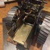
237 forum posts 135 photos | Long time, no post!. Well I've had other things on the go and this part of the build makes me go even slower. What with checking, prepping and making bits as I go along, the job of degreasing and etch priming took me ages, as I have to paint outside. It's either the wrong wind direction, temperature, or humidity. I'm now assembling and top coat painting a few bits at a time, being cautious to get the sequence right to account for all my changes. The pump that I redesigned for an alternative mounting tested fine and have played with piercing the eccentric sheave to look like a casting (lots of knob twiddling on the rotary table in the mill) -
Detail on the motion work finished, but I will probably treat the bright steel parts and dull them off a bit. Having dulled off the pump eccentric strap and rod, I like the look of it and rids the model of the non scale shiny mirror finished steel I initially put on all the bright bits. I trialled dulling off the steel rim faces on the W & S Water Cart using sulphuric acid and it worked well, so will use that process on the rest. Among loads of tiny bit manufacturing, I recently spent an evening making up a number plaque for the rear plate. It's only 8mm between fixing centres and the numbers are made from 0.025" tinned copper wire and laid into a bed of solder. The numbers represent the boiller's build/tested month and year. Plate is ready to fit-
Tender has had it's first top coat, along with a few other bits today, so I'm finally making good progress. Regards. |
| Nigel Graham 2 | 17/03/2021 21:59:17 |
| 3293 forum posts 112 photos | Beautiful work! (Goes a gentle shade of green with envy at the quality.
|
| Jon Lawes | 18/03/2021 17:29:49 |
 1078 forum posts | Beautiful. |
| Harry Wilkes | 18/03/2021 18:00:43 |
 1613 forum posts 72 photos | Nice H |
| An Other | 18/03/2021 18:37:48 |
| 327 forum posts 1 photos | Lovely piece of work. |
| Dominic Bramley | 18/03/2021 20:52:51 |
| 60 forum posts 1 photos | Wow! That looking like the business! Dom |
| Richard S2 | 29/03/2021 19:01:15 |
237 forum posts 135 photos | Thank you all for the positive comments. If it inspires people to add more detail to their project, then this topic has done the job. I have finished the front wheels now. Altered the size of the hub caps (reduced) and changed the oiler style-
I decided to stick with a change I considered for the axle and have now finished the Spud ring and pan-
This was straight forward fabrication using visual scale from full size engines. The only problem was finding a way to produce the pan and flange. I found the answer in an old Duraglit tin and used the lid. I think I have managed to get the final top coat on the tender today, amongst other bits, so proceeding quicker now. Redesigned reversing lever and motion work pieces have all been fettled now, so ready for assembly- Layout of the con rod parts following closer full sized design-
Thanks again. Regards. |


 )
)


Please login to post a reply.
Magazine Locator
Want the latest issue of Model Engineer or Model Engineers' Workshop? Use our magazine locator links to find your nearest stockist!
Sign up to our Newsletter
Sign up to our newsletter and get a free digital issue.
You can unsubscribe at anytime. View our privacy policy at www.mortons.co.uk/privacy
Latest Forum Posts
- hemingway ball turner
04/07/2025 14:40:26 - *Oct 2023: FORUM MIGRATION TIMELINE*
05/10/2023 07:57:11 - Making ER11 collet chuck
05/10/2023 07:56:24 - What did you do today? 2023
05/10/2023 07:25:01 - Orrery
05/10/2023 06:00:41 - Wera hand-tools
05/10/2023 05:47:07 - New member
05/10/2023 04:40:11 - Problems with external pot on at1 vfd
05/10/2023 00:06:32 - Drain plug
04/10/2023 23:36:17 - digi phase converter for 10 machines.....
04/10/2023 23:13:48 - More Latest Posts...
- View All Topics
Support Our Partners


Shopping Partners
Subscription Offer

Latest "For Sale" Ads
- Reeves** - Rebuilt Royal Scot by Martin Evans
by John Broughton
£300.00 - BRITANNIA 5" GAUGE James Perrier
by Jon Seabright 1
£2,500.00 - Drill Grinder - for restoration
by Nigel Graham 2
£0.00 - WARCO WM18 MILLING MACHINE
by Alex Chudley
£1,200.00 - MYFORD SUPER 7 LATHE
by Alex Chudley
£2,000.00 - More "For Sale" Ads...
Latest "Wanted" Ads
- D1-3 backplate
by Michael Horley
Price Not Specified - fixed steady for a Colchester bantam mark1 800
by George Jervis
Price Not Specified - lbsc pansy
by JACK SIDEBOTHAM
Price Not Specified - Pratt Burnerd multifit chuck key.
by Tim Riome
Price Not Specified - BANDSAW BLADE WELDER
by HUGH
Price Not Specified - More "Wanted" Ads...
Get In Touch!
Do you want to contact the Model Engineer and Model Engineers' Workshop team?
You can contact us by phone, mail or email about the magazines including becoming a contributor, submitting reader's letters or making queries about articles. You can also get in touch about this website, advertising or other general issues.
Click THIS LINK for full contact details.
For subscription issues please see THIS LINK.
Digital Back Issues


Donate

 Register
 Log-in
Model Engineer Magazine
- Percival Marshall
- M.E. History
- LittleLEC
- M.E. Clock

ME Workshop
- An Adcock
- & Shipley
- Horizontal
- Mill

Subscribe Now
- Great savings
- Delivered to your door

Pre-order your copy!
- Delivered to your doorstep!
- Free UK delivery!
All Forum Topics > Traction engines > Modded 1" Minnie Progress