Forum sponsored by:

WARCO WM-250 lathe family and WM16 mill - 001
........advice and support for owners.
| Ed Duffner | 18/05/2015 22:02:19 |
| 863 forum posts 104 photos | Thank you very much gents for your thoughts and links, I shall explore with a cuppa. I think at first I'd use the supplied lead-screws and I know they're not ideal but cost has to be kept to a minimum (might have to sell one of my guitars!). I have made a couple of Delrin lead-screw nuts for a lathe using the heating and splitting method. I could possibly do the same for the mill to help reduce backlash and I understand there's a setting in the CAM packages to set up backlash parameters. Andrew, for the engraving work I have an old Black and Decker rotary tool and I believe the top speed is 24000rpm. I can probably make a suitable mount to place it alongside the main spindle for the small footprint that it will operate in. I also have a proper engraving tool, the vibrating type, but not sure that would be so good mounted on a solid machine. Here is an example photo of the engraving I am thinking of doing. the letters are 3mm high. At the moment I'm making a guide jig to do this by hand with punches. I requested quotes to make a single stamp for this job and was quoted £78 by one company and £157 from another. both excluding VAT and P+P.
Thanks again,
|
| Andrew Johnston | 19/05/2015 11:14:56 |
 7061 forum posts 719 photos | Ed: I've never come across backlash compensation in CAM programs. It would make more sense for it to be in the controller software? I guess that the other important parameter for a high speed spindle is runout, especially as the cutters are generally pretty small. The prices for the stamps seem pretty reasonable to me if you're doing more than one piece. And certainly so compared with the time, and cost, needed to do any sort of conversion. John: I have a Series II Tormach, and it is still as supplied. At the time I bought it seemed to be the only sensibly priced CNC mill available off the shelf that would allow 4th axis machining and would cope with the size of work I do. The steppers do make some odd noises, almost musical, when machining arcs, but at the moment there is no overwhelming reason to upgrade to the Series III steppers that are on offer. Likewise I might at some point upgrade to the new controller, but there are many other more pressing calls on cash at the moment. I think the speeder (I thought it was a tripler?) is still available, but it is not cheap. If and when I need to do any more engraving or a lot of machining with small cutters (<2mm) I plan to invest in a secondary spindle and VFD, as sold by ArcEuroTrade. Andrew
Andrew |
| Bowber | 19/05/2015 12:21:49 |
| 169 forum posts 24 photos | I've engraved brass and Aluminium fine on my mill only running at 2450 rpm, you just have to go slowly. I tend to use a 3 flute carbide bit, it's not an engraving bit but more of a countersink. The trouble though it you have to control the depth carefully but it gives good results for engraved plates. I also have a home built router running a Kress head, this is much better for plastics but isn't as accurate for height and XY control as it's using rolled trapezoid screws. Steve Edited By Bowber on 19/05/2015 12:22:26 |
| colin rawson | 21/05/2015 12:23:13 |
| 4 forum posts | i purchased a rdg verion of the weis milling machines
its called the rdg -16vsm a few years ago
its the same as the warco wm14
and my motor brushes are on the way out whats the best place to buy replacements
thanks for any help colin
|
| John Rudd | 21/05/2015 12:42:22 |
| 1479 forum posts 1 photos | Posted by colin rawson on 21/05/2015 12:23:13:
i purchased a rdg verion of the weis milling machine its the same as the warco wm14 and my motor brushes are on the way out whats the best place to buy replacements thanks for any help colin
Warco?
|
| colin rawson | 21/05/2015 13:00:14 |
| 4 forum posts | just waiting for a reply from warco
thanks colin
|
| Ron Vale | 25/06/2015 17:32:56 |
| 24 forum posts | Does anyone know of a company who does a plastic cover to fit over a WM16? |
| mechman48 | 24/08/2015 18:40:28 |
 2947 forum posts 468 photos | Got round to my toduit list & set to making a new compound slide gib key; the original provided was an abysmal piece of mild steel, obviously hand ground at the manufacturers, why it took me so long to do a new one is beyond me; probably down to the 'get your finger out ' not being to the fore front... The OEM gib key...
OEM 'gib'... couldn't even get the angles correct...
Piece of scrap steel ?...
Machining new brass key...
New key, much better fit, although dovetail undercuts way to big!
Also modified the locking screw...
That's another 'mod' off my toduit list... George. |
| its-smee | 08/09/2015 12:40:28 |
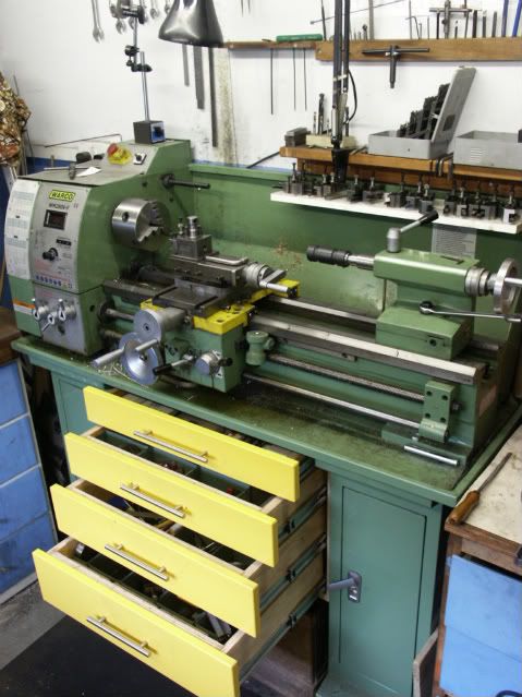
| 42 forum posts 17 photos | At the back end of last year I purchased a Warco VM250V-F lathe and this year a Warco WM 16 mill. Since I purchased the Lathe Warco have modified the Stand and fitted shelves instead of a kick plate. As space is a premium I decided to "do a mod" The kick plate came in two pieces so I fitted suitable supports and using the plates created extra shelving |
| its-smee | 08/09/2015 12:50:40 |
| 42 forum posts 17 photos | I was able to obtain from work some scrap 5mm plastic sheeting and 10mm makralon from a damaged machine guard. After watching various video's on you tube and the picture of the "gold fish bowl" on this forum I decided to try to reproduce them. The rear chip guard is free standing and just slots down the back. The front guard sits on top of the table and does not inhibit the use of the "T" slot. I had sufficient material to make two guards, one with cutout for vice and one with a plain front for times when the vice is not being used.
|
| JasonB | 08/09/2015 13:00:10 |
 25215 forum posts 3105 photos 1 articles | You might want to add a couple of diagonal braces or a panel behind the shelves as the old plate in the middle triangulated the stand to reduce side to sid emovement. I went with draws under mine with a solid back to keep things rigid.
|
| its-smee | 08/09/2015 13:39:24 |
| 42 forum posts 17 photos | A valid point Jason. the shelves are screwed down but as soon as I can get some sheet steel I will be putting a back on for extra support. The draws look good, I never gave that a thought. now I will have to come up with ver 2 |
| Alan Rawlins | 08/09/2015 15:27:53 |
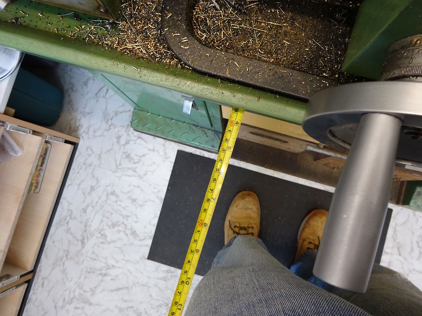
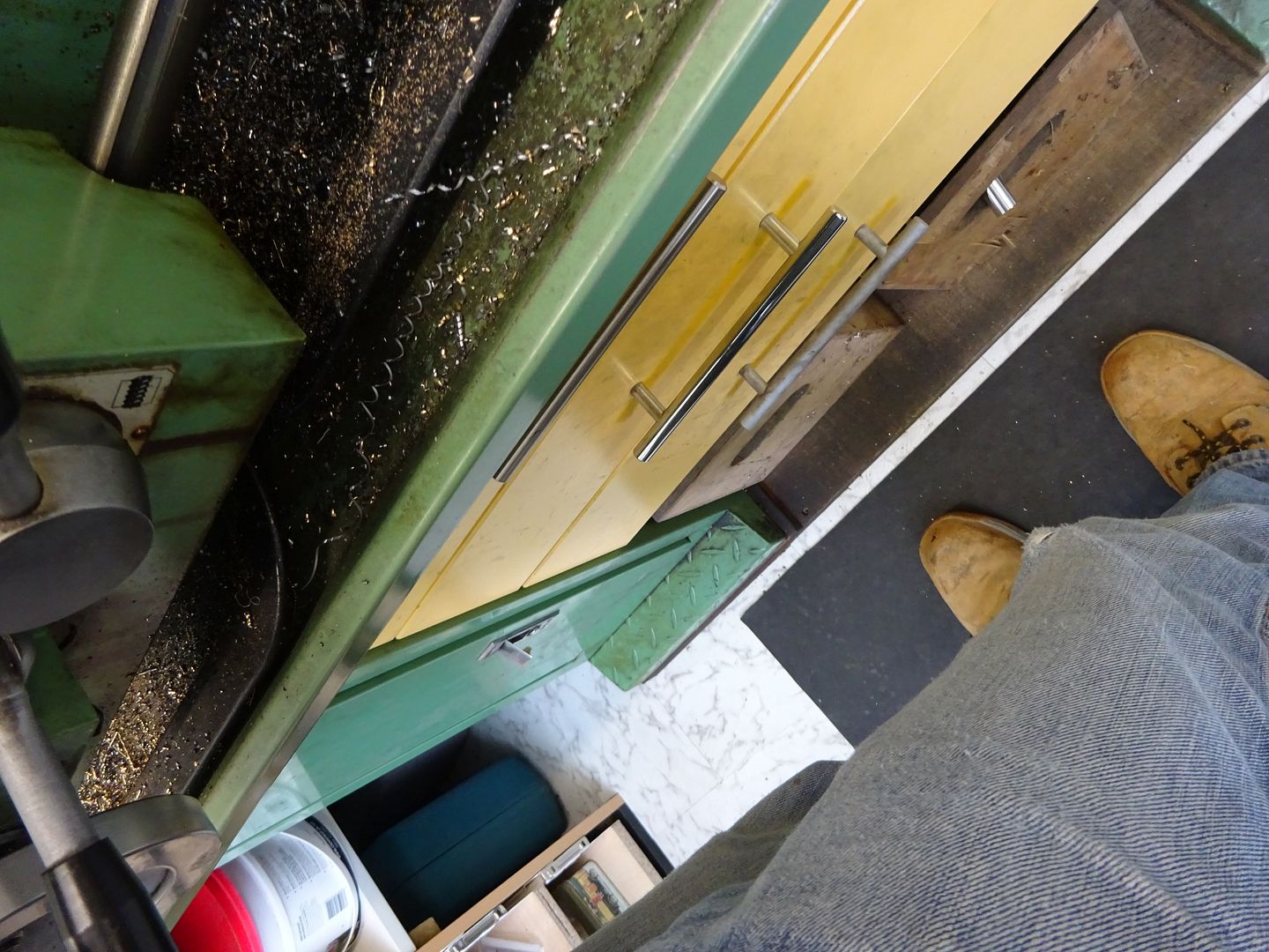
| 74 forum posts | Jason B, I do like your drawer idea, Did you buy the drawer runners from somewhere. The drawers them selves, did you make these and if you did what did you make them from? Do the drawer fronts get in the way of your knees at all? Apart from the drawers being useful they make a crappy stand look a lot better too. |
| its-smee | 08/09/2015 16:00:17 |
| 42 forum posts 17 photos | I agree Alan the drawers are a good idea. it is just a pity the colour is awful and doesn't go with the Warco Green |
| JasonB | 08/09/2015 16:28:01 |
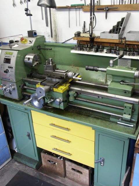
25215 forum posts 3105 photos 1 articles | The basic 5 sides of the carcase is 18mm MFC ( Melamine faced chipboard) not the cheap 15mm contiboard stuff. Draw boxes from 18mm ply biscuit jointed with 6mm MDF bottoms, 18mm MRMDF drawfronts. Runners are easily available full extension ball bearing runners, not sure if I used 30kg or 50Kg ones. There is plenty of knee room as the tray overhangs the cabinet and then the carrage handwheels overhang that so 8-10" knee room no problem.
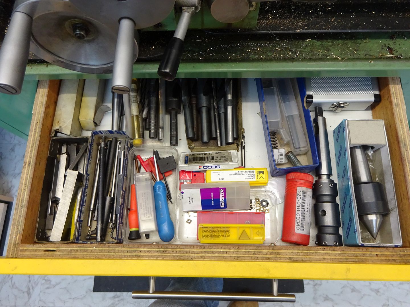
I prefer to keep things in draws or cupboards, as the large hit & miss engines have quite a bit of cast iron I don't like picking things up and getting black hands so keep them away from the fine dust. There is a space below the draws for a couple of ply "scrap" boxes where all the odd come in handy bits go.
Top draw is about 50mm deep and houses small cutting tools, inserts, blacksmith drills, centres etc
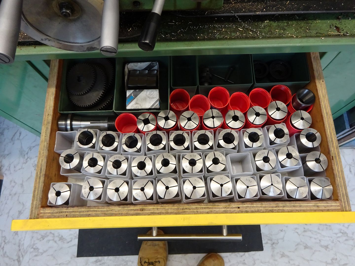
Then one that just takes 5C collets plush chuck jaws, change wheels and so on
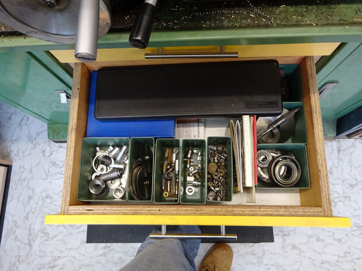
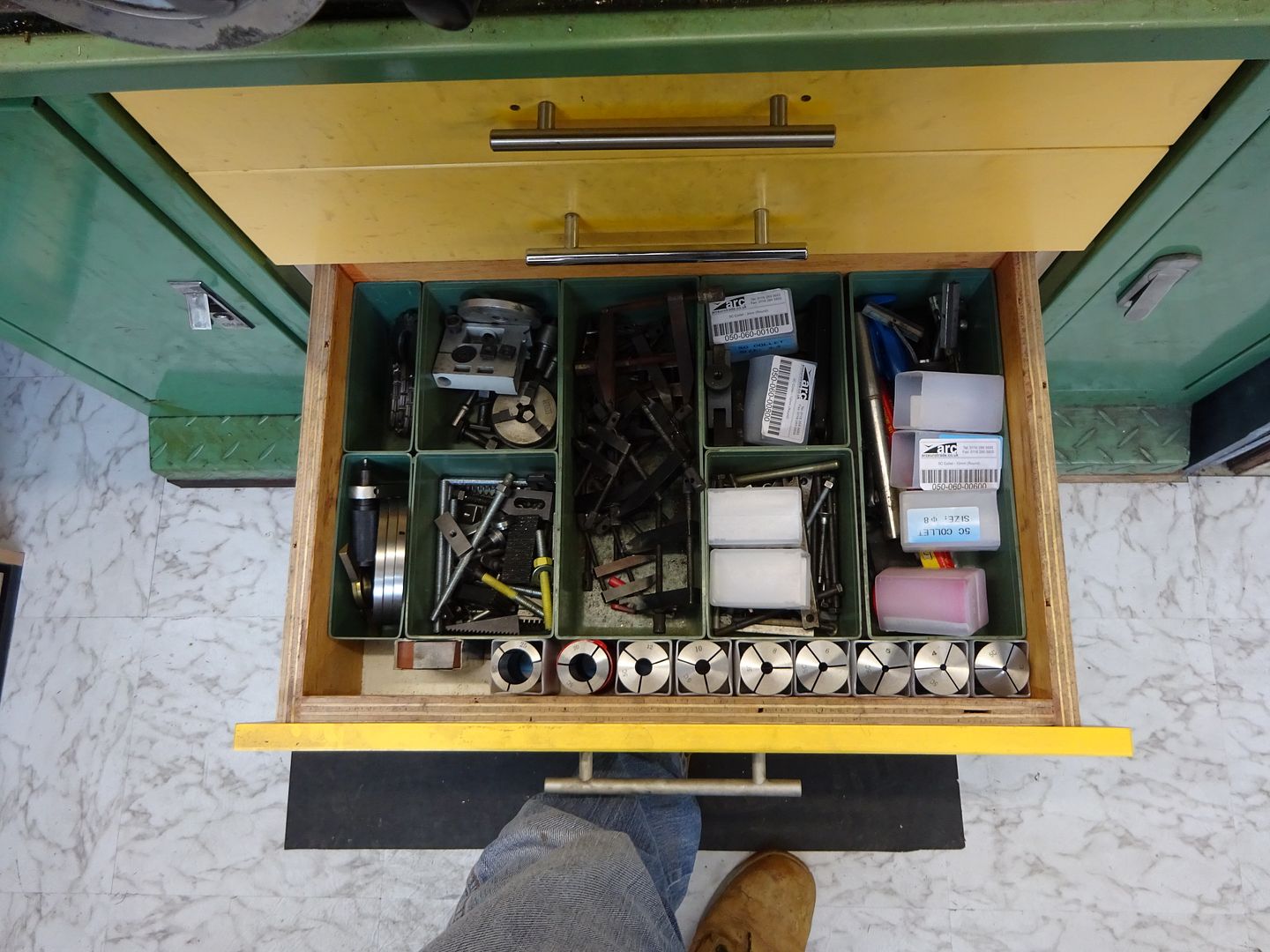
Then an assortment in the two deeper ones below
J
PS I thought the varnished over yellow road marking spray was a good match to the carrage |
| Alan Rawlins | 08/09/2015 16:39:25 |
| 74 forum posts | The yellow colour may be a bit distorted in the photograph as I guess he has tried to make it the same colour as the apron on the lathe. These benches , although they look quite nice are made from very thin material especially the top. Although my concrete floor was level the base of the cabinet and the top were far from straight and parallel.as well as being a lot less than sturdey. I ground the edges of each side of the cabinets to get them level in all planes but the middle bit where the lathe sits was very week. I ended up bolting a piece of 0.75" marine plywood to the top of the cabinets to give me a true base for which to fix the lathe to.When I checked the plywood top for being true and level after bolting it to the cabinets I found it was then spot on. Before bolting the lathe to the plywood i inserted some lead sheet between the lathe and the plywood just in case there were any inconsistencies in the top. This made an excellent base for the lathe. I wonder how any one else got on with just bolting their lathes to the metal cabinet tops just as they came. |
| its-smee | 08/09/2015 18:01:53 |
| 42 forum posts 17 photos | thank you for the description of the drawers JasonB, I didn't spot the relevence of the colour, but as Alan said were you trying to make a match? you have now given me another project to add to the "to do " list Edited By its-smee on 08/09/2015 18:02:19 |
| mechman48 | 09/09/2015 09:27:13 |
2947 forum posts 468 photos | Ditto the drawers... another item on my toduit list... already have one set of runners, just can't seem to get round 'toduit'
|
| Frances IoM | 09/09/2015 09:40:44 |
| 1395 forum posts 30 photos |
any use ? |
| mechman48 | 09/09/2015 10:17:18 |
2947 forum posts 468 photos | Very droll, I like it |

.jpg")
.jpg")
.jpg")
.jpg")
.jpg")
.jpg")


Please login to post a reply.
Magazine Locator
Want the latest issue of Model Engineer or Model Engineers' Workshop? Use our magazine locator links to find your nearest stockist!
Sign up to our Newsletter
Sign up to our newsletter and get a free digital issue.
You can unsubscribe at anytime. View our privacy policy at www.mortons.co.uk/privacy
Latest Forum Posts
- *Oct 2023: FORUM MIGRATION TIMELINE*
05/10/2023 07:57:11 - Making ER11 collet chuck
05/10/2023 07:56:24 - What did you do today? 2023
05/10/2023 07:25:01 - Orrery
05/10/2023 06:00:41 - Wera hand-tools
05/10/2023 05:47:07 - New member
05/10/2023 04:40:11 - Problems with external pot on at1 vfd
05/10/2023 00:06:32 - Drain plug
04/10/2023 23:36:17 - digi phase converter for 10 machines.....
04/10/2023 23:13:48 - Winter Storage Of Locomotives
04/10/2023 21:02:11 - More Latest Posts...
- View All Topics
Support Our Partners


Shopping Partners
Subscription Offer

Latest "For Sale" Ads
- Reeves** - Rebuilt Royal Scot by Martin Evans
by John Broughton
£300.00 - BRITANNIA 5" GAUGE James Perrier
by Jon Seabright 1
£2,500.00 - Drill Grinder - for restoration
by Nigel Graham 2
£0.00 - WARCO WM18 MILLING MACHINE
by Alex Chudley
£1,200.00 - MYFORD SUPER 7 LATHE
by Alex Chudley
£2,000.00 - More "For Sale" Ads...
Latest "Wanted" Ads
- D1-3 backplate
by Michael Horley
Price Not Specified - fixed steady for a Colchester bantam mark1 800
by George Jervis
Price Not Specified - lbsc pansy
by JACK SIDEBOTHAM
Price Not Specified - Pratt Burnerd multifit chuck key.
by Tim Riome
Price Not Specified - BANDSAW BLADE WELDER
by HUGH
Price Not Specified - More "Wanted" Ads...
Get In Touch!
Do you want to contact the Model Engineer and Model Engineers' Workshop team?
You can contact us by phone, mail or email about the magazines including becoming a contributor, submitting reader's letters or making queries about articles. You can also get in touch about this website, advertising or other general issues.
Click THIS LINK for full contact details.
For subscription issues please see THIS LINK.
Digital Back Issues


Donate

 Register
 Log-in
Model Engineer Magazine
- Percival Marshall
- M.E. History
- LittleLEC
- M.E. Clock

ME Workshop
- An Adcock
- & Shipley
- Horizontal
- Mill

Subscribe Now
- Great savings
- Delivered to your door

Pre-order your copy!
- Delivered to your doorstep!
- Free UK delivery!
All Forum Topics > Workshop Tools and Tooling > WARCO WM-250 lathe family and WM16 mill - 001