Forum sponsored by:

Single point Whitworth Threads
| Jon Gibbs | 23/05/2014 08:47:18 |
| 750 forum posts | I hope someone can put me out of my misery please. I have been trying to cut spindle nose threads to match my ML7 which is obviously Whitworth form but I don't have the right form tool to round the creast and roots. What is the best way to single-point thread these - particularly with a simple 55 degree point tool? Looking at the trig, starting with the nominal diameter the thread depth of 0.64 x p isn't deep enough to cut the correct flanks. It looks as if it should be 0.82 x p and that leaves a flat crest which still won't mate with the female thread roots.. Is this truncated form the way to go? Apparently it was the way the US machinists made parts to fit UK standards in WWII?
If so any guidance as to the outside diameter - obviously less than nominal but by how much? It's obviously slightly bigger than (nom - 0.36 x p) but I'm struggling with the intersection of the flank with the radius'd top. Any guidance gratefully received - Many thanks Jon |
| Ady1 | 23/05/2014 09:18:38 |
 6137 forum posts 893 photos | If you can move your tool along a tad before the required depth is reached then you can widen the root so you cut on a single flank to widen the root area i.e. the line which intersects the c in "pitch". Move the tool along so the line intersect/cuts at t (only a suggestion) The usual route I presume would be to finish with a thread chaser Edited By Ady1 on 23/05/2014 09:21:56 |
| Les Jones 1 | 23/05/2014 09:25:15 |
| 2292 forum posts 159 photos | Hi Jon, Les. |
| Bob Brown 1 | 23/05/2014 09:50:05 |
 1022 forum posts 127 photos | When cutting threads I normally off set the compound slide to just over the thread angle so that the tool is cutting most of the material on one flank and only a minimal cut on the other flank, takes a bit of trig to calculate depth but easy enough to do. The OD is in this case 1.125" the only reason to truncate the thread form is speed of production, after all there was a war on. The root is normally taken care of by the tool by just add a radius to the tool tip, crest can be taken care of with a chaser or just carefully rounded off with a file. Or you could either rough it out on the lathe and then run a die down it to clean up the root and crest, RDG sell both taps and dies. If you were going to truncate then it should only be about 0.017" off the diameter for this thread
Bob Edited By Bob Brown 1 on 23/05/2014 09:55:36 Edited By Bob Brown 1 on 23/05/2014 10:06:24 |
| Michael Gilligan | 23/05/2014 10:16:39 |
 23121 forum posts 1360 photos | Jon [and Les] Here is a better image of the one that Les found. Although the Decimal calculation looks tricky, it's worth remembering that Whitworth designed the profile by simplly truncating the crest by H/6 and then blending it as a smooth radius. Use the same process when grinding your tool and " job's a Good 'un " MichaelG. Edited By Michael Gilligan on 23/05/2014 10:17:32 |
| Jon Gibbs | 23/05/2014 11:50:06 |
| 750 forum posts | Thanks for all of the replies and suggestions. I should empahsised that I have made a spindle nose that works ok but I'm just not convinced that the thread flanks are meshing properly as I ended up with well defined crests. So I suppose was looking for a better way. I think I might have found something here though... in "Appendix A: Truncated Whitworth form threads with flat crests" gives the flat topped form. [Incidentally it's quite amusing to see a Chinese company providing a pdf of a British Standard (84:1956) which is labelled as being licensed to South Bank University. BSI will helpfully provide me the same pdf for £204.] ...I'm not sure whether my pedantry in trying to get this better is typical of Myford bods or Flat-earthers but either way I think I can cope. Jon |
| Michael Gilligan | 23/05/2014 12:06:07 |
23121 forum posts 1360 photos | That's a great find, Jon Thanks MichaelG. . P.S. it's worth going back to the parent page and browsing ... amongst all the Chinese characters, there are some familiar numbers. Edited By Michael Gilligan on 23/05/2014 12:10:14 |
| Gordon W | 23/05/2014 12:15:38 |
| 2011 forum posts | I would be more worried about the sharp angle at the bottom of the thread. Stress raiser. Non myford flat earther. |
| Ady1 | 23/05/2014 13:47:59 |
6137 forum posts 893 photos | I'm only a metal bodger but spindle threads are quite important because they do important stuff, so it's worth getting them right if you can gl |
| Jon Gibbs | 23/05/2014 14:09:01 |
| 750 forum posts | Hi Ady, I agree but I'm sort of assuming that the flanks are more important that the crests or roots which is why I'm trying to take the Myford-bod/flat-earther stance here I suppose I also was under the impression that it's the spindle register that provides the concentricity - is that right? Jon
|
| Neil Wyatt | 23/05/2014 14:38:14 |
 19226 forum posts 749 photos 86 articles | If you want the perfect thread form Tracy Tools have three new set of chasers available, using coventry die heads with a holder at £25 a set. I've tried one and it works. You could use it for cutting or finishing these threads. More information in the next MEW or click HERE Neil |
| Jon Gibbs | 23/05/2014 14:47:11 |
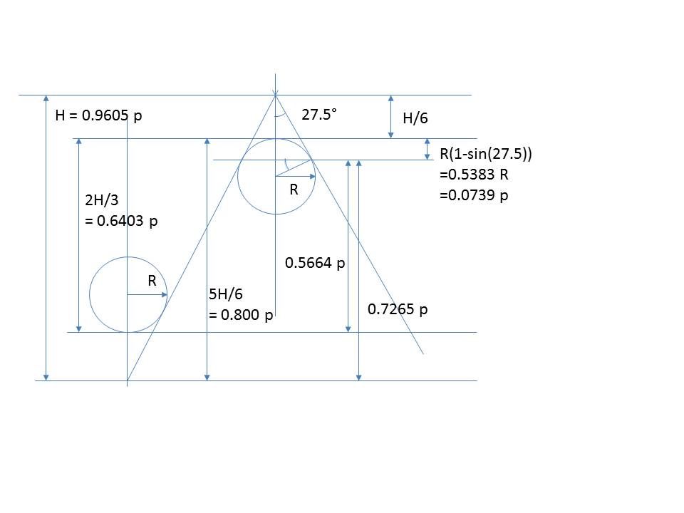
| 750 forum posts | Ok, so checking through my Trig again, the idea of making the major diameter smaller by 0.1478p before single point threading then the crests will be spot-on without needing rounding. This is the same as taking off the U value in Table 21 of BS 84:1956. For the Myford 1 1/8" x 12TPI this means the diameter will be 1.113" instead of 1.125". This means the thread depth with a perfect 55 degree point would need to be 0.9605p (full height) - 0.16p (height / 6) - 0.0739p = 0.7266p. Anything less than a perfect point will need less depth so I guess cutting until thread fits should mean the flanks are meshing ok. Does this make sense? Jon
Edited By Jon Gibbs on 23/05/2014 14:49:57 Edited By Jon Gibbs on 23/05/2014 14:52:47 |
| Jon Gibbs | 23/05/2014 15:01:51 |
| 750 forum posts | Thanks for the suggestion Neil. I will give it some thought and see whether my pocket money will stretch to one. The problem I see with that approach is that It's only good for external chasing isn't it? Jon |
| Jon Gibbs | 23/05/2014 15:46:52 |
| 750 forum posts | Here are my thoughts if it makes it any clearer...
Jon |
| Jon Gibbs | 23/05/2014 15:57:26 |
| 750 forum posts | Sorry for thinking on-line but taking Ady's original suggestion though, the depth could be cut to a smidge over 0.5664p and then broadened until the thread fits which would be better from a stress point of view wouldn't it? ...but is there a way to do this easily with the top-slide set over at 27 degrees? Jon |
| Roderick Jenkins | 23/05/2014 16:29:39 |
 2376 forum posts 800 photos | On my S7 the spindle thread diameter is 1.124" which suggests that it is not a true Whitworth thread form, although it is 55 degrees. The crests are fairly sharp. I think Myford relied on the register to locate the chuck so the backplate threads can be cut fairly loosely with a pointed tool. cheers Rod |
| Ady1 | 23/05/2014 16:44:42 |
6137 forum posts 893 photos | ...but is there a way to do this easily with the top-slide set over at 27 degrees? I would mark the gearwheels off in the geartrain at the start point Once I reached "not quite deep enough" I would then disconnect the geartrain and advance one gear by a couple of teeth, advancing the leadscrew start slightly but not moving the tool this would advance your tool into one side of the flank without going any deeper Edited By Ady1 on 23/05/2014 16:46:13 |
| Jon Gibbs | 23/05/2014 17:43:34 |
| 750 forum posts | Ady, ...Blimey, That will require me having a few minutes to get my head around in a darkened room! ...but seriously, thanks. I guess I will have to try it and see. Jon
|
| Neil Wyatt | 23/05/2014 18:03:21 |
19226 forum posts 749 photos 86 articles | Hi John, My set only goes down (up?) to 14 tpi and I've just tested it, set sideways in the holder, and it would be possible to work it inside a 1 1/4" bore with ease -BUT it would be a left-hand thread.... The other way to cut or finish a 12 tpi internal thread would be to use a 1/2" Whitworth tap. Neil |
| Clive Foster | 23/05/2014 18:44:57 |
| 3630 forum posts 128 photos | Methinks the method given by Ady has far to risk of operator confusion leading to major mess-up. Best to use what was taught to me as the "Zero to Zero" method for screwcutting using the top-side set over at an angle which will allow you to do such broadening cuts at the base of the thread with minimal risk of getting lost. The major advantage of the Zero to Zero method is that it not only does it avoid all the tedious trigonometry to calculate thread depths and sidesteps any errors due to the top-slide angle being a touch off it also gives you an accurately measured account of what you ahve done so if things don't fit you have a fighting chance of figuring out what the gremlins did this time. Basic method is to turn or bore the workpiece to the correct size then mount the screw cutting tool and bring it up to just touch the workpiece. Set both to cross and topslide dials to zero. Pull the tool back clear of the workpiece and crank the saddle along until the tool point is in clear air. Using the cross slide move the tool back past zero until the dial reads the depth of thread to be cut. Set the dial back to zero and use the topslide to bing the tool back far enough to make the first cut. Use the cross slide to pull the tool into and out of cut for saddle travers, cutting passes being made with slide on zero. Cuts are put on with the top-slide. Job done when top slide at zero and last spring cut is clear. Obvoiusly the lathe does all the trigonometry to calculate the top-slide feed needed to achieve the desired depth of thread for whatever angle its set at. Which only needs to be close to half the angle of the thread. My topslide lives at 25° off which works just fine for both 55° and 60° threads. If you need to widen the base of the thread make a cutting pass with the cross slide set a little short of zero with a compensatory extra in-feed on the top-slide to keep the depth the same. For all practical purposes the extra width at the base of the thread will be half the cross slide shift when a compensatory top-side feed of 1.15 times the shift is applied to keep the depth constant. The trig is relatively simple if you want more accurate values but whether your lathe can deliver them is a whole n'other matter. Frankly is far easier to truncate the threading tool to the proper width tip, maybe stoning a radius on the corners too for a perfect job, than mess around with threading techniques. I've seen some right difficult ways of measuring tool truncation. The easy way is to grind it sharp, measure the overall length, figure out how much shorter it needs to be to give the right width at the end and trim it back by the required amount. If you are confident in your trig the amount to trim is easily calculated otherwise refer to thread data book which will tell you how much the real thread is truncated by when compared to a sharp triangle. Clive
|
Please login to post a reply.
Magazine Locator
Want the latest issue of Model Engineer or Model Engineers' Workshop? Use our magazine locator links to find your nearest stockist!
Sign up to our Newsletter
Sign up to our newsletter and get a free digital issue.
You can unsubscribe at anytime. View our privacy policy at www.mortons.co.uk/privacy
Latest Forum Posts
- *Oct 2023: FORUM MIGRATION TIMELINE*
05/10/2023 07:57:11 - Making ER11 collet chuck
05/10/2023 07:56:24 - What did you do today? 2023
05/10/2023 07:25:01 - Orrery
05/10/2023 06:00:41 - Wera hand-tools
05/10/2023 05:47:07 - New member
05/10/2023 04:40:11 - Problems with external pot on at1 vfd
05/10/2023 00:06:32 - Drain plug
04/10/2023 23:36:17 - digi phase converter for 10 machines.....
04/10/2023 23:13:48 - Winter Storage Of Locomotives
04/10/2023 21:02:11 - More Latest Posts...
- View All Topics
Support Our Partners


Shopping Partners
Subscription Offer

Latest "For Sale" Ads
- Reeves** - Rebuilt Royal Scot by Martin Evans
by John Broughton
£300.00 - BRITANNIA 5" GAUGE James Perrier
by Jon Seabright 1
£2,500.00 - Drill Grinder - for restoration
by Nigel Graham 2
£0.00 - WARCO WM18 MILLING MACHINE
by Alex Chudley
£1,200.00 - MYFORD SUPER 7 LATHE
by Alex Chudley
£2,000.00 - More "For Sale" Ads...
Latest "Wanted" Ads
- D1-3 backplate
by Michael Horley
Price Not Specified - fixed steady for a Colchester bantam mark1 800
by George Jervis
Price Not Specified - lbsc pansy
by JACK SIDEBOTHAM
Price Not Specified - Pratt Burnerd multifit chuck key.
by Tim Riome
Price Not Specified - BANDSAW BLADE WELDER
by HUGH
Price Not Specified - More "Wanted" Ads...
Get In Touch!
Do you want to contact the Model Engineer and Model Engineers' Workshop team?
You can contact us by phone, mail or email about the magazines including becoming a contributor, submitting reader's letters or making queries about articles. You can also get in touch about this website, advertising or other general issues.
Click THIS LINK for full contact details.
For subscription issues please see THIS LINK.
Digital Back Issues


Donate

 Register
 Log-in
Model Engineer Magazine
- Percival Marshall
- M.E. History
- LittleLEC
- M.E. Clock

ME Workshop
- An Adcock
- & Shipley
- Horizontal
- Mill

Subscribe Now
- Great savings
- Delivered to your door

Pre-order your copy!
- Delivered to your doorstep!
- Free UK delivery!
All Forum Topics > Beginners questions > Single point Whitworth Threads