Forum sponsored by:

Precision diameters
how to turn to a precise diameter
| Neil Lickfold | 12/05/2014 20:27:50 |
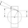
| 1025 forum posts 204 photos | Not sure if this has been covered before. But to get a very precise diameter, I set my compound slide on a 1/2 deg aprox angle. Then when I am close to the diameter I need, I use the compound slide to make the X movement. With this set up it then becomes possible to get to micron sizes. You have to either take some test cuts or use a dti to figure how much each graduation on your cross slide takes off the diameter. Also make sure the cross slide gib is not too loose as well. I use this method for sizing pistons to F3D (6.5cc race engines) where a difference of 0.003 mm in diameter is either too tight or too loose and worn out.
Neil |
| WALLACE | 12/05/2014 20:53:14 |
| 304 forum posts 17 photos | Hi Neil. I was but others might not be so it's worth a post ! If you use a magnifying loop and try to set the angle to 5.7 degrees, the ratio of cross slide feed to actual movement is pretty much exactly 10:1. I remember the angle by thinking of Heinz bakedbeans -57 Varieties !! W. ? |
| Tim Stevens | 12/05/2014 21:22:32 |
 1779 forum posts 1 photos | So, if there is any justice in the world, half a degree (approx = 0.57) gives you 100:1 But if next door comes home and slams his car door, you may be surprised how much difference that will make ... BSA had trouble with 175 Bantam big-ends, ground steel for roller bearings - there was a ripple which promoted failure. The cause - a press at the other end of the works. So, they did press work and bearings on alternate days - it worked. Cheers, Tim Edited By Tim Stevens on 12/05/2014 21:23:34 |
| Neil Lickfold | 13/05/2014 01:30:37 |
| 1025 forum posts 204 photos | With my set up, 2 thou on the compound is 0.001mm diameter. The hardest part of it all was getting the head stock bearing lapped and scraped to run true enough, and then having the end play correct. I can not run my lathe in the high rpm range otherwise it will start to heat up. If it is backed off to run at the higher rpm, it will not be running true enough.
|
| john kennedy 1 | 13/05/2014 06:43:54 |
 214 forum posts 24 photos | Good tip Neil,thanks. Been using a lathe for nearly 50 years (professionally and messing in the shed) and I've never come across that that one. |
| Old School | 13/05/2014 08:44:13 |
| 426 forum posts 40 photos | Neil Like you I am making pistons but for tether car engines of 2.5cc I have just bought some bar to do my 10cc enngines.To get the final fit right it is by feel rather than measurement. I have been considering lapping to remove the last little bit of material almost a polishing operation. I have had my top slide set over but at a much greater angle I will try your method it may get rid of the need to lap. |
| Andrew Johnston | 13/05/2014 11:46:13 |
 7061 forum posts 719 photos | Using the compound slide at an angle is a fairly well known technique, although I rarely use it as model traction engines don't need that sort of accuracy. I'm impressed with the accuracy that is being achieved, but a couple of things puzzle me. One, presumably if the difference between 'good to go' and 'worn out' is only 0.003mm then the lathe needs to be turning parallel to rather better than 0.003mm? Two, presumably you control the workshop environment to avoid temperature related errors? If I need 'tenths' precision I'm afraid I cheat and use the cylindrical grinder. Andrew |
| Neil Lickfold | 13/05/2014 12:24:17 |
| 1025 forum posts 204 photos | You need a lot of things to fall into place to get the accuracy that is for sure. You need the temp to be some what controlled, I have a small room built in my garage just for the lathe, with a dehumidifier and a heater for winter. I have my own mix of oil I use on the slideways, it is just 30/40 motor oil with lucas oil stabiliser and some stp oil treatment in it.The lathe bed has been levelled with a precision machine level to get the warp/twist out of it .The standard Starrett ones are not really accurate enough.I brought my own and am very happy with the results. Saddle has been re shimmed to get the better tolerances. Cross slide is adjusted to be quite neat but can me slide by hand, then the screw and nut assembled and correctly aligned. I made a M8x0.5mm pitch screw and nut so that the inches dial now matches the micrometer dial in metric.The down side is the slowness of the cross slide in travelling any distance.Compound slide is adjusted to be just sliding but not binding.I refitted the compound slide as it was, there was a slight taper in it,either wear or like that from new.I only use my Myford lathe for my precision work and thread cutting. All roughing out/blanking out is done on another lathe I have. I hope others can learn from this , and help them to achieve accuracies that otherwise are not easy to achieve.Even making the M8 fine Pitch thread instead of the course 10 tpi that was in there has been a huge step up in accuracy. As you can tell, I spent a lot of time setting up the lathe to get it do do what I want.
|
| Bob Brown 1 | 13/05/2014 13:38:39 |
 1022 forum posts 127 photos | So how do you manage to measure to these limits 0.003mm? Most "good" micrometers like Mitutoyo are limited to ±2µm or ±0.002mm, and when you get to these sort limits the operator has a lot to do with getting the correct measurement. Are you using optical measurement? I would have thought it was more about fit. |
| Neil Lickfold | 13/05/2014 21:04:21 |
| 1025 forum posts 204 photos | It is a combination of fit for the final position and measure ment. Most model engine liners have a taper of Ø 25um per 10 mm or .0025mm per mm length. So to get the piston to the fitted length if it is 2mm away will require removing .005mm off the diameter. It does take a bit of experience to get it right. If the part has a temperature increase from the turning, you will not make it work, as the size while turning will change. I have a very good mic with a non rotating barrel and use it like a comparator mic. I am in the process of getting a comparator mic with the dial gauage built in. The other way of measuring but is very cumbersome , is to use a Vee block and a low pressure finger clock graduated in .001mm increments. But the total range on such instruments is usually about 0.1mm meaning you have to be within 0.06mm of size to even use it. I cannot measure better than about 0.001mm or so. I can certainly get to better than 0.002mm . An error of 0.001 is going to be about 0.4mm on the piston fit position. Everything has to be degreased and be oil free when measuring. To cut at these small tolerances , I use a mixture of canola oil and about 20-25% crc , for the piston trim I use a positive rake ccmt11 PCD insert. Honing oil is also a very good cutting compound, but is more expensive . I can fit on my Myford a piston easier and get it right compared to using a standard cnc lathe that has 0.001 resolution. To really be able to make these right requires, sub micron lathes which I do not have access to out here in NZ. These pistons could be lapped to size, but those do not perform as well as ones that have been turned to size. In a mass production set up, these pistons are turned in batches with 0.0005mm or so difference in size and the correct graded piston is then selected to fit that liner. But this process , will help those who need to achieve 0.002mm size on parts if it needs it. |
| Andrew Johnston | 14/05/2014 11:28:30 |
7061 forum posts 719 photos | Neil: Thanks for the elucidation. I'm surprised that a turned finish works better than a lapped one. I would have thought that lapping would give a finer finish, which would be better? Any explanation as to why this isn't the case? What sort of Ra values are you achieving on the turned pistons? Regards, Andrew |
| Neil Lickfold | 14/05/2014 12:42:48 |
| 1025 forum posts 204 photos | I do not know the Ra values sorry. But I think the reason it works better is that the interference fit, effectively burnishes the piston to the final running fit size. When lapping , you are taking away these peaks and so the piston can not burnish to get the liner specific fit. I think this is why when you run a piston in another liner, it does not run as good as a new piston that was fitted to that liner. I have not found a way to make the lapped ali pistons work. Hope that helps. Neil |
| Andrew Johnston | 15/05/2014 11:10:49 |
7061 forum posts 719 photos | Neil: It should be possible to calculate a theoretical Ra value knowing the tool profile, DOC and feedrate. I would imagine that to be commensurate with the dimensional accuracies quoted you must be achieving values around 0.1µm. Anyway, thanks for the replies, they have given an insight into precision machining. Regards, Andrew |
| Bazyle | 15/05/2014 14:09:46 |
 6956 forum posts 229 photos | Apart from being able to remove small amounts because of the different cutting action what makes surface/cylindrical grinders so accurate? Do they have finer feed screws? I notice they tend to have big handles so is that giving more control and a bigger dial on what is still a 'coarse' 10tpi screw, or do they have a finer one? I'm really asking about control along the lines of this topic rather than quality of build, weight, etc. |
| Neil Wyatt | 15/05/2014 18:30:16 |
 19226 forum posts 749 photos 86 articles | Hi Bazyle, I've always assumed that the much lower forces and cuts involved mean much less deflection and less heating of the workpiece. I think finer feeds just take advantage of this. Neil |
| Muzzer | 15/05/2014 19:15:29 |
 2904 forum posts 448 photos | I must be missing something. Surely these engines run stink hot and the pistons will run a fair bit hotter than the barrels, so if you have effectively zero clearance when cold you will have issues when the piston heats up. Certainly, the conditions will differ considerably from those described during machining. The other difficulty concerns the lubrication. You need a layer of lubricant (the fuel mix presumably) which requires a gap - is 2 microns enough? Whether or not this claimed level of accuracy is actually achieved, what is believed to be driving the requirement? You aren't going to be losing much mixture (compression) between the barrel and the piston and the heat transfer isn't going to be affected either. Are there dyno results that show some form of benefit? To be honest I'm not convinced these values are required, achievable or even measurable in this environment. Merry |
| Andrew Johnston | 15/05/2014 19:48:59 |
7061 forum posts 719 photos | Posted by Neil Wyatt on 15/05/2014 18:30:16:
I've always assumed that the much lower forces and cuts involved mean much less deflection and less heating of the workpiece. Lower forces yes, less heat no! Think about how hot a HSS toolbit gets when you grind it. The actual cutting process is fairly inefficient, as the grains of the grinding wheel are operating with a large negative rake, so heat is generated. On my small cylindrical grinder the wheelhead feedscrew is geared to be effectively 40tpi at the hand wheel, ie, 25 thou per rev. Here are the basic controls:
The main handwheel drives the wheelhead screw via a reduction gear. The small lever above the green electrical switch operates a stop for the handle. On top of the handwheel is a fine feed worm drive. The knob top right is for fine adjsutment of the table swivel. Here are the graduations on the main hand wheel:
Each major division is 1 thou, each small division a tenth of a thou. These are direct reading, ie, the diameter reduces by twice the value. The worm drive allows a fine feed against the stop:
Each division is 25 micro inches, ie, half of one tenth on the diameter. Everything is designed with known, and repeatable, allowances for backlash. For instance the wheelhead feedscrew has a large (100lb+) counterweight on the back:
The machine itself is pretty heavy 1300lbs. There is also an art to grinding, sparkout is important for obtaining consistent sizing. Regards, Andrew |
| jason udall | 15/05/2014 20:05:49 |
| 2032 forum posts 41 photos | We used to run centerless grinders on plunge feed..I used to do the spc for them...doesn't matter what spc is..but we logged each part...working typically. .0.5 micron.for hundreds of parts...infact once warmed up I believe the error was shared with the instrumentation. .three hole carbide bushed air gauge. .resolving to 0.1 micron...finish ..well parts needed "roughing" up if too good ( never got that but there you go)..finish can be too good..mirror doesn't hold oil...... But again sparkout is critical. .too long and you glase the wheel and part stops spinning.. |
| JasonB | 15/05/2014 20:11:16 |
 25215 forum posts 3105 photos 1 articles | Could one of you gentlemen enlighten me as to what "sparkout" is, I assume it is something like trueing the wheel or getting a fresh cutting surface. J |
| Andrew Johnston | 15/05/2014 20:20:14 |
7061 forum posts 719 photos | Sorry, using jargon; it means traversing the grinding wheel across the work without touching the feed controls. At the first pass there are a few sparks, at the next pass fewer sparks and so on. When there are no, or very few, sparks it is time to measure. It's the equivalent of a pass or two with a boring bar without touching the crossslide. Andrew |


Please login to post a reply.
Magazine Locator
Want the latest issue of Model Engineer or Model Engineers' Workshop? Use our magazine locator links to find your nearest stockist!
Sign up to our Newsletter
Sign up to our newsletter and get a free digital issue.
You can unsubscribe at anytime. View our privacy policy at www.mortons.co.uk/privacy
Latest Forum Posts
- *Oct 2023: FORUM MIGRATION TIMELINE*
05/10/2023 07:57:11 - Making ER11 collet chuck
05/10/2023 07:56:24 - What did you do today? 2023
05/10/2023 07:25:01 - Orrery
05/10/2023 06:00:41 - Wera hand-tools
05/10/2023 05:47:07 - New member
05/10/2023 04:40:11 - Problems with external pot on at1 vfd
05/10/2023 00:06:32 - Drain plug
04/10/2023 23:36:17 - digi phase converter for 10 machines.....
04/10/2023 23:13:48 - Winter Storage Of Locomotives
04/10/2023 21:02:11 - More Latest Posts...
- View All Topics
Support Our Partners


Shopping Partners
Subscription Offer

Latest "For Sale" Ads
- Reeves** - Rebuilt Royal Scot by Martin Evans
by John Broughton
£300.00 - BRITANNIA 5" GAUGE James Perrier
by Jon Seabright 1
£2,500.00 - Drill Grinder - for restoration
by Nigel Graham 2
£0.00 - WARCO WM18 MILLING MACHINE
by Alex Chudley
£1,200.00 - MYFORD SUPER 7 LATHE
by Alex Chudley
£2,000.00 - More "For Sale" Ads...
Latest "Wanted" Ads
- D1-3 backplate
by Michael Horley
Price Not Specified - fixed steady for a Colchester bantam mark1 800
by George Jervis
Price Not Specified - lbsc pansy
by JACK SIDEBOTHAM
Price Not Specified - Pratt Burnerd multifit chuck key.
by Tim Riome
Price Not Specified - BANDSAW BLADE WELDER
by HUGH
Price Not Specified - More "Wanted" Ads...
Get In Touch!
Do you want to contact the Model Engineer and Model Engineers' Workshop team?
You can contact us by phone, mail or email about the magazines including becoming a contributor, submitting reader's letters or making queries about articles. You can also get in touch about this website, advertising or other general issues.
Click THIS LINK for full contact details.
For subscription issues please see THIS LINK.
Digital Back Issues


Donate

 Register
 Log-in
Model Engineer Magazine
- Percival Marshall
- M.E. History
- LittleLEC
- M.E. Clock

ME Workshop
- An Adcock
- & Shipley
- Horizontal
- Mill

Subscribe Now
- Great savings
- Delivered to your door

Pre-order your copy!
- Delivered to your doorstep!
- Free UK delivery!
All Forum Topics > Hints And Tips for model engineers > Precision diameters