Forum sponsored by:

Suggestions please.
| Ramon Wilson | 28/03/2011 22:06:36 |
 1655 forum posts 617 photos | Hi Graham,
Given that you mean with the means at your disposal ie short of a decent shadograph ......
Could you not try 'copying' said tool by laying it cutting side down on your scanner and taking an image - then enlarge image and check against Cad drawn lines at 29 inclusive
Would that be an acceptable 'simple solution' ? - I don't know - just a thought.
Regards - Ramon Edited By Ramon Wilson on 28/03/2011 22:08:57 |
| blowlamp | 28/03/2011 22:13:58 |
 1885 forum posts 111 photos | If you have a rotary table and milling machine, you could make a simple jig from MDF or plastic etc with a couple of 29 deg slots to hold the cutter and present it to the grinding wheel in a predictable manner. It would be easy to regrind the tool if you need to as well.
Martin. |
| John C | 28/03/2011 22:26:43 |
| 273 forum posts 95 photos |
Hi Grey,
Would a sine bar and slip gauges inside (say) the parallel jaws of a milling vice work? You'd still need to sight the tool edges inside the included angle but you could maybe feel the rock in the tool.You could nip the jaws up onto parallels even if this left the tool nose unsupported.
All th ebest,
John |
| Terryd | 28/03/2011 22:33:43 |
 1946 forum posts 179 photos | Hi Graham, Ramon, Ramon's idea is similar to a suggestion I made about measuring the angle of screw threads a while ago. It actually works very well but in your case you need to place the tool 'face down' on the scanner platen. Also, the settings of your scanner need to be set to a high resolution so that you can enlarge the image without degradation. I have used this method very successfully for all sorts of applications over the years. Terry |
| John Haine | 28/03/2011 23:05:22 |
| 5563 forum posts 322 photos | I doubt that there is any simple way of checking it that will be any more accurate than the Quorn was in making it! I must say though that Ramon's & Terry's idea with the scanner is inspired....having spent quite a long time adapting the bits of an Aldi microscope with CCD camera and a cheap Proxxon XY table into a travelling video microscope last year, I wish that I'd thought of this first! |
| Sam Stones | 29/03/2011 05:28:29 |
 922 forum posts 332 photos | Hi Graham,
Although the optics may not be perfect, do you have access to an old slide projector? You could examine its potential as the starting point for a shadowgraph.
In my case, I'm able to turn to a couple of toolmaker friends who might possess a professional shadowgraph. Then of course, there are the technical colleges who may perhaps provide some help.
Regards,
Sam
|
| Stewart Hart | 29/03/2011 08:02:06 |
 674 forum posts 357 photos | A projector can be easily rigged up using a mag light and a magnifying glass like this
[IMG]http://i431.photobucket.com/albums/qq32/sbwhart/Modmodder/IMG_2156.jpg[/IMG]
You just have to calibrate it using something of known size a set of radius gauges works fine, to get its magnification
When you know its magnification just draw up a screen for comparison.
This is the result
[IMG]http://i431.photobucket.com/albums/qq32/sbwhart/Modmodder/IMG_2155.jpg[/IMG]
Stew
PS
I can never get the insert pic thing to work |
| Steve Garnett | 29/03/2011 10:16:42 |
| 837 forum posts 27 photos | Posted by Stewart Hart on 29/03/2011 08:02:06: I can never get the insert pic thing to work I had trouble with that once too. But actually it's quite easy; use the icon with the little mountains in it, and post the URL in that. So your two pictures:   |
| Les Jones 1 | 29/03/2011 11:57:42 |
| 2292 forum posts 159 photos | Hi All, Just a word of caution about the scanner idea. Last week when someone mentioned the idea for checking thread angles I thought I would try it. I tried at first using a flatbed scanner (Using 5mm threaded rod for the test.) This worked quite well. I then thought I would try a "Veho" USB microscope. This did not give the correct result for the angle. I think it must stretch the image in one direction. So I think to use the method the result should be checked by scanning a second time with the object at 90 degrees to the first scan / photograph. I used "Paintshop pro" to measure the angle. When drawing lines on top if the image the angle of the lines is displayed. I also have a very low tech suggestion but I suspect that it will not be accurate enough. Clamp the tool down on top of a sheet of paper. Hold a straight edge against the side of the tool making sure it is fully in contact with the edge then draw a line along the straight edge. Repeat for the other edge then use a large protractor to measure the angle between the lines. Les. |
| John C | 29/03/2011 12:29:23 |
| 273 forum posts 95 photos |
Hi Gray,
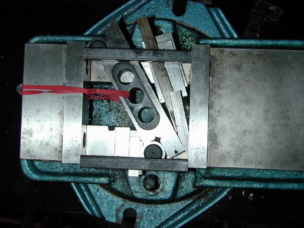
Further to my post above, I rigged up a mock up of the vice and sine bar. The two bars between the vice jaws are machined together to the same length to ensure the jaws are parallel and the rubber band is to keep the sine bar and the slips together. I put a key ring LED under the tool to show any gap. The 'tool' is a bit of steel I ground to 29 deg internal angle on my Worden, set using an ordinary protractor, so as you can see it would need a skim to be spot on.
The first photo shows is without flash and with the matching bars removed to show the keyring LED shining in the gap, the second shows the general idea.
Hope this helps,
( And I also hope I have got the right end of the stick!!)
John
|
| Steve Garnett | 29/03/2011 13:04:34 |
| 837 forum posts 27 photos | Posted by Les Jones 1 on 29/03/2011 11:57:42: I then thought I would try a "Veho" USB microscope. This did not give the correct result for the angle. I think it must stretch the image in one direction. So I think to use the method the result should be checked by scanning a second time with the object at 90 degrees to the first scan / photograph. I used "Paintshop pro" to measure the angle. When drawing lines on top if the image the angle of the lines is displayed. I also have a very low tech suggestion but I suspect that it will not be accurate enough. Clamp the tool down on top of a sheet of paper. Hold a straight edge against the side of the tool making sure it is fully in contact with the edge then draw a line along the straight edge. Repeat for the other edge then use a large protractor to measure the angle between the lines. Les, I'm sure you are right about the aspect ratio changing when it shouldn't. One thing you can easily do as a sanity check with the microscope is to place two steel rules at right-angles to each other and the piece you are measuring at the junction of them. If you print the result on paper, you should be able very easily to come up with a compensation value, just by measuring the same indicated distance on each and establishing the difference between them. In principle you could do this with a scanner as well, although to do it easily you'd need scales printed on acetate. |
| Terryd | 29/03/2011 13:30:38 |
1946 forum posts 179 photos | Hi Steve, Do remember that printers aren't very accurate with aspect ratios, you need to calibrate them first or use a calibration print. A relatively easy way to check is to print a regular shape (circle, square) in both landscape and portrait and check the aspect ration. Instead of two rulers on a scanner try scanning graph paper or good quality squared paper. Regards Terry Edited By Terryd on 29/03/2011 13:41:07 |
| Steve Garnett | 29/03/2011 13:42:20 |
| 837 forum posts 27 photos | Posted by Terryd on 29/03/2011 13:30:38: Do remember that printers aren't very accurate with aspect ratios, you need to calibrate them first or use a calibration print. Terry, the whole point of this method is that the calibration is included with the scan! When you print the image you want, you are also printing the image of the rulers, or transparent calibration sheet - this way you can measure the scales and compensate directly from your final image print. With the acetate sheet method, you have a slightly worse problem, because you don't want to print it initially on a device with inherent linearity errors, so you may be better off scribing a sheet rather than printing it. OTOH, you may find that you get an acceptable image from the rules laid on the platten. I'll give it a go later and see if I can illustrate this. |
| Les Jones 1 | 29/03/2011 15:18:01 |
| 2292 forum posts 159 photos | Hi Steve, I don't actually need to do any angle measurements at the moment. The idea just seemed worth trying. I also found that the image produced by the USB microscope was more difficult to line up the measuring lines on so I have discounted using it. Back to Graham's original question. Using the acme thread gauge with a suitable parallel (eg some feeler gauges.) on one side of the tool may work. A variation on the rotary table idea might also work if the tool is not too small. With the rotary table mounted on a mill and the tool clamped to it use a dial gauge to align one edge of the tool with the X or Y axis. Note the reading on the rotary table then repeat for the other edge and calculate the difference. Les. |
| blowlamp | 29/03/2011 15:20:41 |
1885 forum posts 111 photos | Has anyone contacted The National Physical Laboratory yet, to see if they can help?
 Martin. |
| Terryd | 29/03/2011 15:37:45 |
1946 forum posts 179 photos | Hi Steve, My point was that by using only one check, which is inaccurate, The scan or the print. Surely it is better to know the inaccuracy in each component so that
simple calculations will give correct answer whether just printing,
scanning or both? If you know the accuracy of your scanner any inaccuracy can be corrected in your graphics program and angular measurements etc can be made on screen in a cad program without printing. By using graph paper to calibrate you can check the accuracy at different places on the platen. Why use acetate? You only have to place the rulers face down on the platen and they will be scanned. Personally, I still think that I would prefer to know the accuracy of my scanner and printer rather than having to add rulers every time. Best regards Terry Edited By Terryd on 29/03/2011 15:43:51 |
| Steve Garnett | 29/03/2011 16:32:43 |
| 837 forum posts 27 photos | Sorry - had to go out for an hour, but I did what follows in less than five minutes (including fetching the scanner) before I went: Posted by Terryd on 29/03/2011 15:37:45: My point was that by using only one check, which is inaccurate, The scan or the print. Surely it is better to know the inaccuracy in each component so that simple calculations will give correct answer whether just printing, scanning or both? If you know the accuracy of your scanner any inaccuracy can be corrected in your graphics program and angular measurements etc can be made on screen in a cad program without printing. By using graph paper to calibrate you can check the accuracy at different places on the platen. This method covers both in one go, and generally the linearity errors in scanners are pretty small - it's the scaling inaccuracy that can be much greater. Posted by Terryd on 29/03/2011 15:37:45: Why use acetate? You only have to place the rulers face down on the platen and they will be scanned. Personally, I still think that I would prefer to know the accuracy of my scanner and printer rather than having to add rulers every time. You are quite correct about the acetate - it's not needed. But fixing the rules at right-angles, and in a sensible alignment only took a moment with two bits of magic tape; it really wasn't a problem. What you get from this is either a large scan (which I haven't included) that would enable you to establish the aspect ratio error pretty accurately, and another one which would enable you to make a pretty accurate (well in terms of grinding) measurement directly, without any need to apply calibration corrections at all. 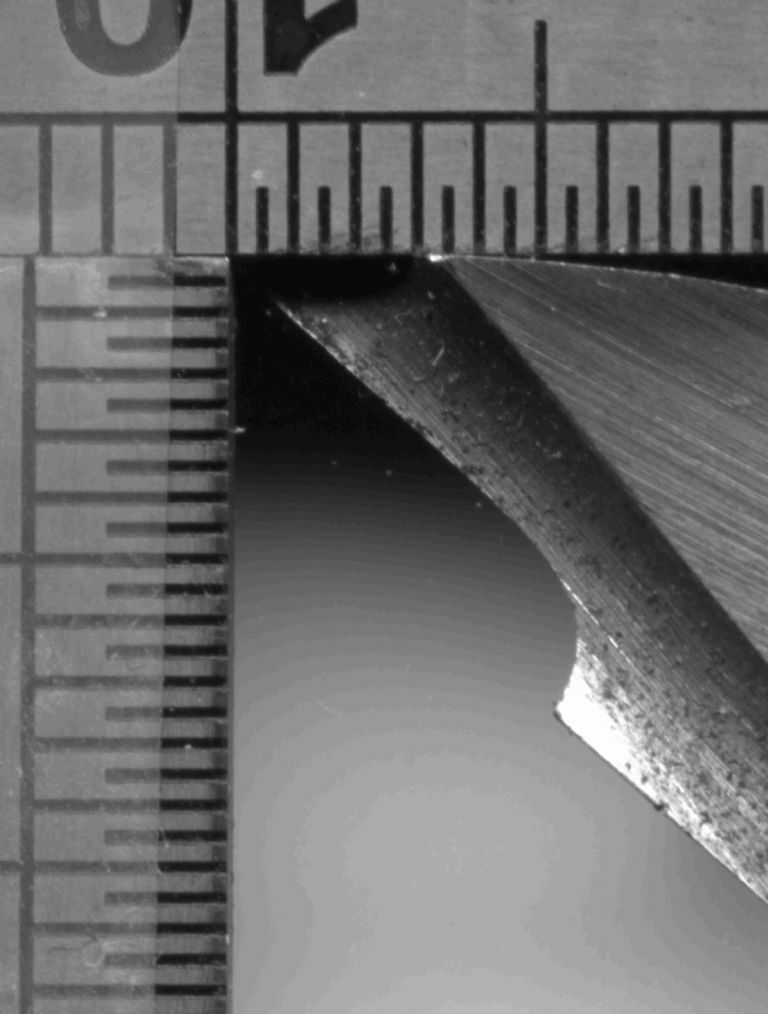 The small divisions are 0.5mm. And it would not be difficult to establish the relative angles here, I think. Please excuse the lump of tool steel - I inherited it, and it's untouched. No I don't know why it's like that at all - it's only there for illustrative purposes. |
| Geoff Theasby | 29/03/2011 17:21:28 |
| 615 forum posts 21 photos | As much for my own edification as to help, but could you measure the angle of each side of the tool with an angle gauge, perhaps an electronic one, against the horizontal, then you could check that each side was in agreement? You might have to turn to tool on its side to do this. Regards Geoff |
| Steve Garnett | 29/03/2011 17:28:50 |
| 837 forum posts 27 photos | Incidentally I checked the scaling inaccuracy on the scanned result above, and it's about 0.33%, FWIW. And you can calculate directly the angle that the first bit of grinding makes to the vertical by plotting intersecting lines (I used Serif Draw plus) very carefully on a blown-up image, measuring the difference between them and using Arctan (H difference/V difference), arrive at an answer. What you discover when you look at the above one very carefully though is that the ground line is only straight over about half of its length, so the accuracy is somewhat compromised anyway, unless you are very careful. Edited By Steve Garnett on 29/03/2011 17:29:27 |
| Steve Garnett | 29/03/2011 17:38:10 |
| 837 forum posts 27 photos | Posted by Geoff Theasby on 29/03/2011 17:21:28: As much for my own edification as to help, but could you measure the angle of each side of the tool with an angle gauge, perhaps an electronic one, against the horizontal, then you could check that each side was in agreement? You might have to turn to tool on its side to do this. Geoff, I think that there are perhaps as many ways of doing this as you could think of! The only thing you have to be aware of with each one is where the potential errors might creep in, and how much confidence you could reasonably have in the result as a consequence. So in my example above, I've measured the angle of the ground edge to the horizontal, and if I've got the sums and error direction correct, it's 47.26 degrees minus 0.33%. Electronic angle gauges have an inherent accuracy of about 0.1 degrees, I believe. You'd have to be very careful about physical alignment of the gauge though, because you wouldn't have much surface to work with, would you? |
Please login to post a reply.
Magazine Locator
Want the latest issue of Model Engineer or Model Engineers' Workshop? Use our magazine locator links to find your nearest stockist!
Sign up to our Newsletter
Sign up to our newsletter and get a free digital issue.
You can unsubscribe at anytime. View our privacy policy at www.mortons.co.uk/privacy
Latest Forum Posts
- *Oct 2023: FORUM MIGRATION TIMELINE*
05/10/2023 07:57:11 - Making ER11 collet chuck
05/10/2023 07:56:24 - What did you do today? 2023
05/10/2023 07:25:01 - Orrery
05/10/2023 06:00:41 - Wera hand-tools
05/10/2023 05:47:07 - New member
05/10/2023 04:40:11 - Problems with external pot on at1 vfd
05/10/2023 00:06:32 - Drain plug
04/10/2023 23:36:17 - digi phase converter for 10 machines.....
04/10/2023 23:13:48 - Winter Storage Of Locomotives
04/10/2023 21:02:11 - More Latest Posts...
- View All Topics
Support Our Partners


Shopping Partners
Subscription Offer

Latest "For Sale" Ads
- Reeves** - Rebuilt Royal Scot by Martin Evans
by John Broughton
£300.00 - BRITANNIA 5" GAUGE James Perrier
by Jon Seabright 1
£2,500.00 - Drill Grinder - for restoration
by Nigel Graham 2
£0.00 - WARCO WM18 MILLING MACHINE
by Alex Chudley
£1,200.00 - MYFORD SUPER 7 LATHE
by Alex Chudley
£2,000.00 - More "For Sale" Ads...
Latest "Wanted" Ads
- D1-3 backplate
by Michael Horley
Price Not Specified - fixed steady for a Colchester bantam mark1 800
by George Jervis
Price Not Specified - lbsc pansy
by JACK SIDEBOTHAM
Price Not Specified - Pratt Burnerd multifit chuck key.
by Tim Riome
Price Not Specified - BANDSAW BLADE WELDER
by HUGH
Price Not Specified - More "Wanted" Ads...
Get In Touch!
Do you want to contact the Model Engineer and Model Engineers' Workshop team?
You can contact us by phone, mail or email about the magazines including becoming a contributor, submitting reader's letters or making queries about articles. You can also get in touch about this website, advertising or other general issues.
Click THIS LINK for full contact details.
For subscription issues please see THIS LINK.
Digital Back Issues


Donate

 Register
 Log-in
Model Engineer Magazine
- Percival Marshall
- M.E. History
- LittleLEC
- M.E. Clock

ME Workshop
- An Adcock
- & Shipley
- Horizontal
- Mill

Subscribe Now
- Great savings
- Delivered to your door

Pre-order your copy!
- Delivered to your doorstep!
- Free UK delivery!
All Forum Topics > Hints And Tips for model engineers > Suggestions please.