Forum sponsored by:

radius dresser
| Nobby | 06/01/2011 16:47:28 |
 587 forum posts 113 photos | Hi
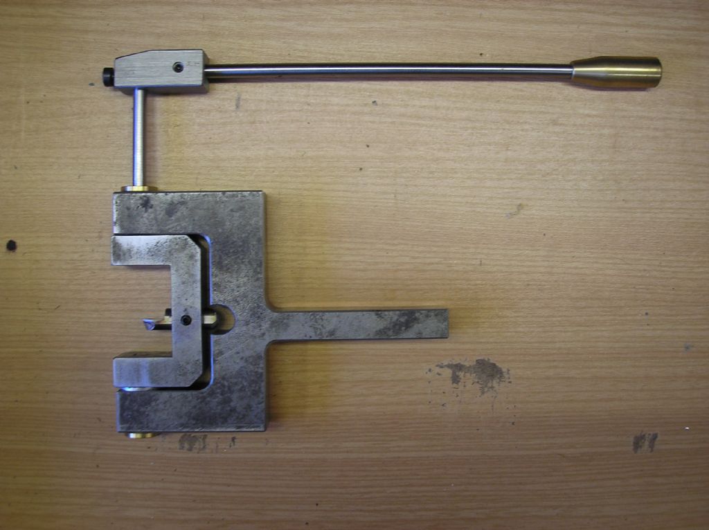
With this set up is it posible to turn a complete ball and part it off
Nobby |
| JasonB | 06/01/2011 17:53:03 |
 25215 forum posts 3105 photos 1 articles | No, the part holding the tool will hit the bar the ball is being turned from before a full shere can be cut.
J |
| Sam Stones | 07/01/2011 04:04:26 |
 922 forum posts 332 photos | Hi Nobby,
JasonB is correct.
However, by making a cutter cranked towards the lathe chuck, you can generate a complete sphere. It certainly won't be as rigid as the straight cutter in your device.
In ME years ago, there was a spherical turning attachment described. I've no reference to it but you can see a photograph of the one I made in my album entitled `Stop Gaps'.
Regards,
Sam |
| Nobby | 07/01/2011 15:39:06 |
587 forum posts 113 photos | Hi Sam & Jason B
Thank you for input on this issue .I made a radius attatchment using my boring head I made .as you may have seen on my uploaded photos . I will try your cranked method.
Regards Nobby
|
| TomK | 07/01/2011 17:23:11 |
| 83 forum posts 23 photos | Nobby
If you look at the tools in this radii cutter you will see the one at the top is cranked. this allows you turn spheres.
tomk

|
| Nobby | 07/01/2011 22:39:49 |
587 forum posts 113 photos | Hi Tom K
Thank you for info The boring head one i made was used mainly for turning radius electrodes for the sparking m/c with a micrometer adjustmet i could turn to the size required by adjusting the dail .
Regards Nobby
|
| Sam Stones | 08/01/2011 01:31:23 |
922 forum posts 332 photos | 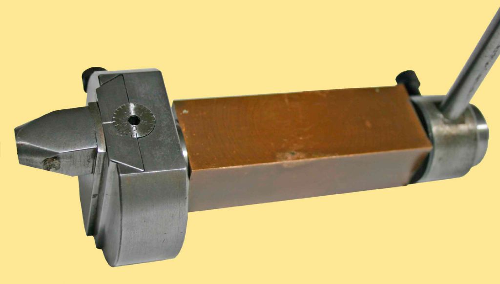 Hi Nobby, Perhaps a few words about the spherical turning attachment which I hinted at earlier. This version works in a totally different sense, with the cutter (a short length of round HSS), inserted into the end of the nose piece on the left of the image. The cutter is inclined downwards at about 5 degrees to provide `front’ clearance, while the protruding squared-off tip of the cutter is the `top’ cutting face. In other words, the main cutting force would tend to push the cutter further into the nose piece. Setting up requires that the axis of the device (holding the bronze bit in the tool post), is horizontal and exactly in the same plane as the horizontal axis of the lathe. The device axis should also be parallel with the cross slide movement. Using the cross slide, the tip of the cutter is then brought into line with the vertical axis of the workpiece so that when the device is rotated with the lever, the swept arc will generate a sphere. Bingo! As you can see, the dovetailed slide has a calibrated dial to adjust the depth of cut. I used a 40TPI thread for the tiny lead-screw, ie. 0.025" per revolution. The slide could be locked in place (finger tight) with the Allan screw just visible behind.
Although I didn't use the device other than to generate spheres, by raising it to a higher level in the tool post, a radius could be generated similar to that found on the outside of hand-wheels.
I trust this will be of interest.
Best regards,
Sam |
| JasonB | 08/01/2011 08:11:16 |
25215 forum posts 3105 photos 1 articles | For those that say their tools can form a complete parted off shere can I ask if they have to take two goes at the cut as the amount of metal that needs removing from the parent bar and the distance it needs to be from the chuck would make it virtually impossible to take a finishing cut over the whole sphere due to it not being supported by much. I can see Sam's type of cutter being better at this than the "C" type.
I have a Bedair type ball turner and the best I could manage was the balls on this governor which are integral to 3/32" the arms, even then I had to have a lot of work protruding from the chuck and finish the end half before reducing the shank and rounding the back half.
Jason |
| Nobby | 08/01/2011 11:28:12 |
587 forum posts 113 photos | 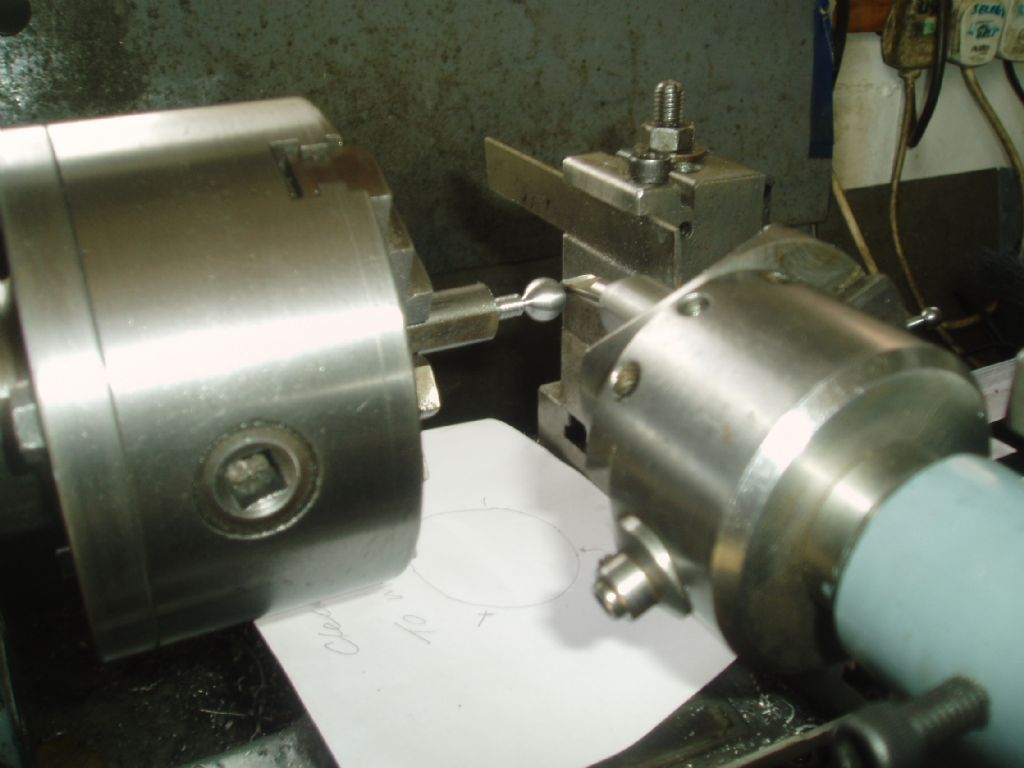 Hi Sam Thank you for information . Its was of great interest. The boring head in the photo can also be screwed on my Kerrys mill drill arbour
Regards Nobby
|
| Nobby | 08/01/2011 11:50:49 |
587 forum posts 113 photos | Hi Jason B ref radius dresser
I encounted the problem trying to cut a complete ball as the fixture swinging round would hit the chuck . thats why I wondered how to cut a complete ball .thats why i looked at the up and over way. C.N C users would not have this problem IE start position circle center end postition. etc ( in English)
Regards Nobby |
| JasonB | 08/01/2011 12:56:49 |
25215 forum posts 3105 photos 1 articles | Thanks Nobby, thats what I was thinking, your type would seem to have better clearance.
As you can see with my style of cutter the side of the insert and the post it fixes to gets in teh way when trying to do a full circle. I will make another post to take the longer diamond shape inserts or just a HSS bit that can be ground to suit.
 Jason |
| Nobby | 08/01/2011 13:19:02 |
587 forum posts 113 photos | Hi Jason B
I will post a picture of my other rad, cutter and see what you think
Regards Nobby |
| John Olsen | 08/01/2011 23:31:32 |
| 1294 forum posts 108 photos 1 articles | I have one of the type that Sam showed in his picture earlier, made from the George Thomas book if I recall correctly. With any type of spherical turning attachment, you do have to watch out for clearance around the chuck. This type is better than some, but you do need to make sure that the top of the dovetail slide and the adjustment knob are going to clear the chuck jaws as you swing it over that way. I've never tried to part the ball right off as I have never needed to, but I beleive you could with a suitable shaped tip. It is certainly easy to neck the handle down more than you meant to very easily. Incidently I have fitted mine into a Dickson style quick change holder. This is worth doing when you are making a lot as you don't have to set up the centre height every time. You can put the blank into the chuck, turn down the end to the diameter needed, change to a parting tool, make the groove for the neck, then change to the spherical atttachment and turn the sphere shape almost as fast as I can type this. regards John |
| ady | 09/01/2011 10:30:54 |
| 612 forum posts 50 photos | A form tool at the back was used in the past for mass production. Remove most material manually and then finish with the tool, or a couple of tools if the cutting area is too large. You automatically get a good finish as well. |
| Terryd | 09/01/2011 11:04:29 |
 1946 forum posts 179 photos | Hi Jason, I fancy a Bedair type ball turner having seen his video on YouTube, after seeing yours, and when my workshop is rebuilt it will be one of my first projects. However I recently saw a modification using triangular inserts and one side was in line with the left hand side of the sliding toolpost rather than the point in line with the centre. I hope that makes sense. This would allow the cutting tool to advance to the centre of the ball being made (theoretically) when cutting the LH radius nearest to the chuck. I forget now where I saw it but it may have been on the Madmodder forum, I'll have a look around and see if I can find it. Regards Terry |
| JasonB | 09/01/2011 11:11:40 |
25215 forum posts 3105 photos 1 articles | Sounds like a god Idea.
If you do make one similar to mine I would suggest that the rotating parts are mounted to the left of the base plate as it gets a bit tight under the 5" chuck and won't fit with the 6" that I also have. A couple of large CSK socket screws would not go amis either rather than nuts.
J Edited By JasonB on 09/01/2011 11:13:59 |
| Ramon Wilson | 09/01/2011 13:00:57 |
 1655 forum posts 617 photos | I've been following this thread with some interest as have often felt that such a tool would be useful to have. Having never cut any spheres with anything other than a form tool though I felt it much better to 'listen' and learn.
The last few posts however rang a bell as quite a few years back, whilst at work, somehow this subject came up. At that time I could recall having seen or read somewhere that this could be done on a milling machine using a boring head for cutting and a dividing head for rotation.
A short piece of ally bar about an 1" diameter had a centre put in one end and that end had a relief put in with a parting tool leaving the end the same width as it's diameter. (hope that makes sense). The dividing head with three jaw chuck mounted was set up in a conventional (horizontal) fashion with the piece held in the three jaw and supported by a tailstock centre.
The boring head had a cranked tool set in reverse ie pointing inwards and set to the approximate radius of the ball desired. With the axis of mill and dividing head in line and centred about the turned end portion of the blank the head was rotated as the boring tool was brought into contact. As the table was raised the ball was generated seemingly quite magically as I recall. Because of the centre a full ball could not be formed which does not answer the original question - 'How does one form a complete ball and part off'
but a large enough ball to see that it works well enough was produced
Apart from this one time however, done purely to see if this method would work, I have never heard of it described nor had need to use it.
Looking at the George Thomas type tool however I felt the similarity of operation could be seen.
Ha ha - Just been out to the workshop and a quick rummage in the old tool chest found this
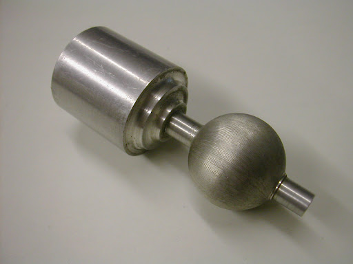 This is the actual part described - I thought it was lurking somewhere. You can see the generated tool marks quite easily - this was just a test piece after all but a round nose tool would no doubt improve matters considerably.
As said - doesn't answer Nobby's question directly but may be of interest to some one
Regards - Ramon
Edited By Ramon Wilson on 09/01/2011 13:02:59 |
| Terryd | 09/01/2011 13:18:06 |
1946 forum posts 179 photos | Hi Jason, I see what you mean from your photograph above. Looking at the picture would it not be possible to mount the baseplate so that it is in the axis of the cross slide rather than across it, i.e. the mounting bolts/screws are in one tee slot? Hi Ramon, That looks like an interesting technique, thanks for the posting, regards Terry Edited By Terryd on 09/01/2011 13:20:37 |
| John Stevenson | 09/01/2011 13:36:14 |
 5068 forum posts 3 photos | This is the milling technique, it's a very old method and appears in books around the turn of the 20 th century. 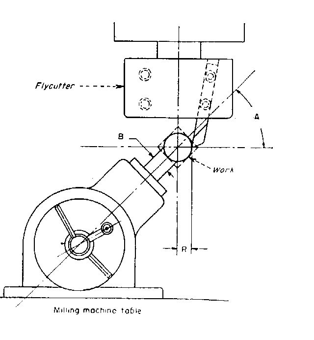 John S. |
| Ramon Wilson | 09/01/2011 13:53:58 |
1655 forum posts 617 photos | You know as we get older I'm sure many would agree that you can't remember what you did five minutes ago. Things way back though are sometimes a bit better
 Johns pic triggered something and yes here it is - an identical pic in a book '150 Practical Ideas on Metalwork Production' page 49.
It was given to me in 1980 by a Len Evans - someone reverred in our area as a truly great engineer, sadly no longer with us. This is obviously what I had remembered at work - the fact that it was set at an angle to complete as much of the ball as possible obviously overlooked.
The book still sits in my book case but what I hadn't realised until an hour ago was that Lenny had actually annotated it for me. Definitely now a treasured possession as opposed to a valued one!
John, you are obviously a very busy person - how on earth do you find time to dwell in the ME world (that's a genuine observation not flippancy).
Regards - Ramon
Why don't you see the spelling mistakes until after you've posted
Edited By Ramon Wilson on 09/01/2011 13:54:29 Edited By Ramon Wilson on 09/01/2011 13:56:29 Edited By Ramon Wilson on 09/01/2011 14:01:26 |
Please login to post a reply.
Magazine Locator
Want the latest issue of Model Engineer or Model Engineers' Workshop? Use our magazine locator links to find your nearest stockist!
Sign up to our Newsletter
Sign up to our newsletter and get a free digital issue.
You can unsubscribe at anytime. View our privacy policy at www.mortons.co.uk/privacy
Latest Forum Posts
- *Oct 2023: FORUM MIGRATION TIMELINE*
05/10/2023 07:57:11 - Making ER11 collet chuck
05/10/2023 07:56:24 - What did you do today? 2023
05/10/2023 07:25:01 - Orrery
05/10/2023 06:00:41 - Wera hand-tools
05/10/2023 05:47:07 - New member
05/10/2023 04:40:11 - Problems with external pot on at1 vfd
05/10/2023 00:06:32 - Drain plug
04/10/2023 23:36:17 - digi phase converter for 10 machines.....
04/10/2023 23:13:48 - Winter Storage Of Locomotives
04/10/2023 21:02:11 - More Latest Posts...
- View All Topics
Support Our Partners


Shopping Partners
Subscription Offer

Latest "For Sale" Ads
- Reeves** - Rebuilt Royal Scot by Martin Evans
by John Broughton
£300.00 - BRITANNIA 5" GAUGE James Perrier
by Jon Seabright 1
£2,500.00 - Drill Grinder - for restoration
by Nigel Graham 2
£0.00 - WARCO WM18 MILLING MACHINE
by Alex Chudley
£1,200.00 - MYFORD SUPER 7 LATHE
by Alex Chudley
£2,000.00 - More "For Sale" Ads...
Latest "Wanted" Ads
- D1-3 backplate
by Michael Horley
Price Not Specified - fixed steady for a Colchester bantam mark1 800
by George Jervis
Price Not Specified - lbsc pansy
by JACK SIDEBOTHAM
Price Not Specified - Pratt Burnerd multifit chuck key.
by Tim Riome
Price Not Specified - BANDSAW BLADE WELDER
by HUGH
Price Not Specified - More "Wanted" Ads...
Get In Touch!
Do you want to contact the Model Engineer and Model Engineers' Workshop team?
You can contact us by phone, mail or email about the magazines including becoming a contributor, submitting reader's letters or making queries about articles. You can also get in touch about this website, advertising or other general issues.
Click THIS LINK for full contact details.
For subscription issues please see THIS LINK.
Digital Back Issues


Donate

 Register
 Log-in
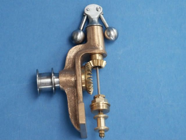
Model Engineer Magazine
- Percival Marshall
- M.E. History
- LittleLEC
- M.E. Clock

ME Workshop
- An Adcock
- & Shipley
- Horizontal
- Mill

Subscribe Now
- Great savings
- Delivered to your door

Pre-order your copy!
- Delivered to your doorstep!
- Free UK delivery!
All Forum Topics > General Questions > radius dresser