Forum sponsored by:

How to determine the pressure angle of gears
| Clive Pearson | 18/11/2010 18:47:52 |
| 2 forum posts | I need to remake two of the gears in the lead screw gearbox of my Harrison L5 Lathe ( 3 speed ) .Since the new gears will have to mesh with some of the existing gears I understand it is important that they are both cut with the same pressure angle commonly 14.5 or 20 degrees.Having read Ivan Laws book Gears and Gear Cutting I still am unable to see how you determine the pressure angle from the physical dimensions of the existing gears .Any suggestions please .The gears are aprox. 2.5ins. dia. |
| Michael Cox 1 | 18/11/2010 19:11:23 |
| 555 forum posts 27 photos | Hi Clive,
I recently had the same problem of determining the pressure angle of a gear. The most successful way is described here:
I hope this helps
Mike |
| Peter G. Shaw | 18/11/2010 21:18:39 |
 1531 forum posts 44 photos | Hey Mike, That's excellent. Although I haven't yet tried any gear wheel cutting, I have used CAD to draw circles and teeth using Ivan Law's ideas in his book, indeed his approximation was the only way I could draw some teeth - I forget which way round it is, but depending on the number of teeth, the pitch circle is either inside or outside one of the other circles, and this means that either the involute curve can be drawn, or it cannot. The reason why it cannot is because it cannot be extended backwards. Using Law's approximation gives success. But your idea to determine the pressure angle, assuming you are the same Mike, is excellent. Regards, Peter G. Shaw |
| Michael Cox 1 | 18/11/2010 22:57:02 |
| 555 forum posts 27 photos | Hi Peter,
Thanks for your kind words.
The website is mine.
Mike |
| Clive Foster | 18/11/2010 23:08:42 |
| 3630 forum posts 128 photos | Fortunately for those lacking high CAD skills, or even CAD at all, there is an adequate direct measurement method for determining the PA of normal involute gears. I lifted this from a reliable source and its worked out fine for me
Firstly you need to know the diametrical pitch, DP, of the gear, basically number of teeth per inch of pitch circle diameter. For practical purposes pitch circle diameter runs round half way up the tooth. As its always a whole number and only a few numbers are used best guess estimation is usually good enough unless you are watch making.
Given the DP take a measurement over any reasonable small number of teeth with whatever equipment you have. 3 to 5 teeth for a chord length of around 1/8 of a circle usually does just fine. Multiply the cosine of the 'PA' by 3.1416 and divide by the 'DP' add this to your measurement, this should be the measurement over one more tooth if its not the same, change the the 'PA' and try again.
Example:-
10dp 14.5 pa, 30 teeth,
Measurement over 3 teeth .776",
Cos 14.5° = 0.986147
(0.986147 x 3.1416) = 3.04
3.04/10 = 0.304
0.304" + 0.776" = 1.080" which will be the measurement over 4 teeth if the gear is
14.5° PA."
Obviously 10 DP is easy on the maths.
In practice you only have 14.5° and 20° pressure angles to choose from for general purpose gears so the difference is usually pretty conclusive. Its not an exact to umptyfour decimal places calculation, just a nearest to result for separating sheep and goats. I'd be very careful with gears having heavily modified addendum, dedendum and teeth shape tho'. It works, after a fashion, with stub teeth but some judgement is needed.
There is probably a direct version for module gears but substituting nearest DP is good enuf.
Heavily engineered devices such as car and motorcycle gearboxes often include gear pairs which are way outside standard formulae. Especially Japanese motorcycle gearboxes where its not uncommon to find teeth numbers up to one tooth different from what the standard formulas give for gears of that DP or Module and diameter.
Clive
Edited By Clive Foster on 18/11/2010 23:09:49 |
| John Olsen | 19/11/2010 09:31:29 |
| 1294 forum posts 108 photos 1 articles | Speaking of Japanese gearboxes....back a few years (like in the seventies) I was rebuilding a Honda 100 that I had thrashed to death. Checking the gears, I found signs of wear on one of them. Checked the part number, ordered a new one, and put the bottom end together. It bound up...so I thought that can't be right, took it down again. After a bit of two and fro, I found that the new gear had one more teeth than the old one. So I took it out, and took both of them to the dealer. We tried again, sending the old and new pair to the importer...still came back with one that wouldn't fit. Third try we managed to get the importer to check more carefully and they sent one that was correct. I still wonder how it came about that they had the wrong ones...it can't have been a modification because the mating gear would also have to change, and it is unlikely that increasing one gear by one tooth and reducing the mating one is going to work, there was no sign of any different mating gears anyway. (I was changing both, as one does.) My only theory is that someone made a mistake setting up the machine for a batch of spares...I wonder how many got put in without the problem being spotted? The gearbox would go together, but did not rotate as freely as it should have. I bet they didn't last too long like that. Before anyone makes any critical remarks, my other bike at the time was a Triumph 250 single of exactly the same year, and that had problems that were far more serious built in. regards John |
| Howard Jones | 19/11/2010 11:56:38 |
| 70 forum posts 112 photos | too many opportunities for error in that method. an american guy gave me the simplest method. get a piece of glass. roll out a sausage of plasticene on the glass. roll the gear along the plasticene to make a plasticene rack. measure the angle of the slope of the rack tooth face. this corresponds to the pressure angle. |
| Michael Cox 1 | 19/11/2010 12:38:23 |
| 555 forum posts 27 photos | Hi Howard,
I tried the plasticene sausage method and could not get repeatable results. I also had problems on my mod 1 gears with the plasticene detaching cleanly from the gear.
Mike |
| Stub Mandrel | 19/11/2010 19:15:51 |
 4318 forum posts 291 photos 1 articles | my mod 1 gears with the plasticene detaching cleanly from the gear. Try WD40 on the plasticene Neil |
| Billy Mills | 21/11/2010 01:27:48 |
| 377 forum posts | Why not try rebuilding the missing/damaged teeth instead of making the whole gear. There are a few articles on the web from dovetailing in a new block of metal to inserting pins and then weld metal. A form tool to fit whatever the gap profile is- which you would need anyway- then cut the gaps you need. Regards, Alan. |
| Anthony Ashgrove | 04/12/2010 18:09:40 |
| 9 forum posts | Hi Clive,
I have an exel spreadsheet for gear cutting data, by measuring your existing gears dia and no of teeth etc you should be able establish the PA of your gears, if you want a copy please email me aashgrove@yahoo.com, also get a catalogue from HPC Gears very useful!!
regards
Tony Ashgrove |
| Andrew Johnston | 04/12/2010 22:42:04 |
 7061 forum posts 719 photos | Errr I don't think so, the OD of the gear and the number of teeth will enable you to determine the DP of the gear, but they'll tell you absolutely nothing about the PA. Regards, Andrew |
| John Stevenson | 04/12/2010 23:13:37 |
 5068 forum posts 3 photos | It is possible to define the PA by measuring over 3 or 5 teeth and a set of tables. However the tolerances in commercial gears is that wide they exceed the differences between 14.5 and 20 degrees PA. Another problem is many commercial gears are modified to give stronger tooth forms, quieter running that it puts all normal calculations out the window. 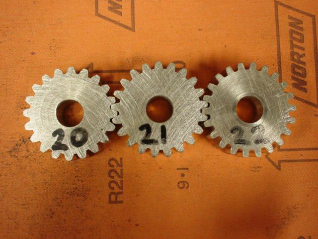 Take these three gears, all cut on the same OD but only the 22 tooth is correct as regards normal calculations. Trying to measure anything on the 21 and 20 teeth will get you nowhere but they are all 20 PA gears. John S. |
| Anthony Ashgrove | 05/12/2010 11:56:25 |
| 9 forum posts | Andrew,
In my defence, you have not seen the spreadsheet so cannot seeall the data it provides. The PA affects the tooth length, so you can identify the different PA's the spreadsheet gives all the critical measurements of the tooth not just OD so I believe you can establish the PA, by the way you can calculate gear data for any PA not just the 14.5 or 20 degree PA commonly used, if you would like a copy please ask.
Regards
Tony Ashgrove |
| Andrew Johnston | 05/12/2010 22:25:56 |
7061 forum posts 719 photos | Hi Tony, Indeed I haven't seen the spreadsheet, and if it contains extra information, then I am sure it is possible to determine the PA. My point was that it is isn't possible to determine the PA given only the OD and number of teeth. I'm not sure what the 'tooth length' refers to, but I would be interested in seeing a copy of the spreadsheet. I've sent you an email request for same. Regards, Andrew |
Please login to post a reply.
Magazine Locator
Want the latest issue of Model Engineer or Model Engineers' Workshop? Use our magazine locator links to find your nearest stockist!
Sign up to our Newsletter
Sign up to our newsletter and get a free digital issue.
You can unsubscribe at anytime. View our privacy policy at www.mortons.co.uk/privacy
Latest Forum Posts
- *Oct 2023: FORUM MIGRATION TIMELINE*
05/10/2023 07:57:11 - Making ER11 collet chuck
05/10/2023 07:56:24 - What did you do today? 2023
05/10/2023 07:25:01 - Orrery
05/10/2023 06:00:41 - Wera hand-tools
05/10/2023 05:47:07 - New member
05/10/2023 04:40:11 - Problems with external pot on at1 vfd
05/10/2023 00:06:32 - Drain plug
04/10/2023 23:36:17 - digi phase converter for 10 machines.....
04/10/2023 23:13:48 - Winter Storage Of Locomotives
04/10/2023 21:02:11 - More Latest Posts...
- View All Topics
Support Our Partners


Shopping Partners
Subscription Offer

Latest "For Sale" Ads
- Reeves** - Rebuilt Royal Scot by Martin Evans
by John Broughton
£300.00 - BRITANNIA 5" GAUGE James Perrier
by Jon Seabright 1
£2,500.00 - Drill Grinder - for restoration
by Nigel Graham 2
£0.00 - WARCO WM18 MILLING MACHINE
by Alex Chudley
£1,200.00 - MYFORD SUPER 7 LATHE
by Alex Chudley
£2,000.00 - More "For Sale" Ads...
Latest "Wanted" Ads
- D1-3 backplate
by Michael Horley
Price Not Specified - fixed steady for a Colchester bantam mark1 800
by George Jervis
Price Not Specified - lbsc pansy
by JACK SIDEBOTHAM
Price Not Specified - Pratt Burnerd multifit chuck key.
by Tim Riome
Price Not Specified - BANDSAW BLADE WELDER
by HUGH
Price Not Specified - More "Wanted" Ads...
Get In Touch!
Do you want to contact the Model Engineer and Model Engineers' Workshop team?
You can contact us by phone, mail or email about the magazines including becoming a contributor, submitting reader's letters or making queries about articles. You can also get in touch about this website, advertising or other general issues.
Click THIS LINK for full contact details.
For subscription issues please see THIS LINK.
Digital Back Issues


Donate

 Register
 Log-in
Model Engineer Magazine
- Percival Marshall
- M.E. History
- LittleLEC
- M.E. Clock

ME Workshop
- An Adcock
- & Shipley
- Horizontal
- Mill

Subscribe Now
- Great savings
- Delivered to your door

Pre-order your copy!
- Delivered to your doorstep!
- Free UK delivery!
All Forum Topics > Beginners questions > How to determine the pressure angle of gears