Forum sponsored by:

Gear milling
| Bill Dawes | 10/12/2009 12:59:03 |
| 605 forum posts | Anyone done any gear cutting with a milling cutter. I did some proper gear hobbing in my apprenticeship days many moons ago but my workshop won't run to that. Not found any supplier so far that does such a cutter.
I have Tubal Caines hand little book and it states that the type of cutter determines the size of gear you can cut (or visa versa I suppose)
Bill D. |
| mgj | 10/12/2009 14:02:02 |
| 1017 forum posts 14 photos | Yes- its quite easy. if you need good info, Ivan Laws book from the Workshop Practise series covers all we would ever need about cutting gears on a vertical mill. Tracy tools do cutters in DP sizes. They are about £16 each. You will possibly need more than one cutter because each cutter only does a limited range of teeth numbers. Buy the right cutter, set up on centre height against the dividing head, apply the infeed for that DP. Cut. 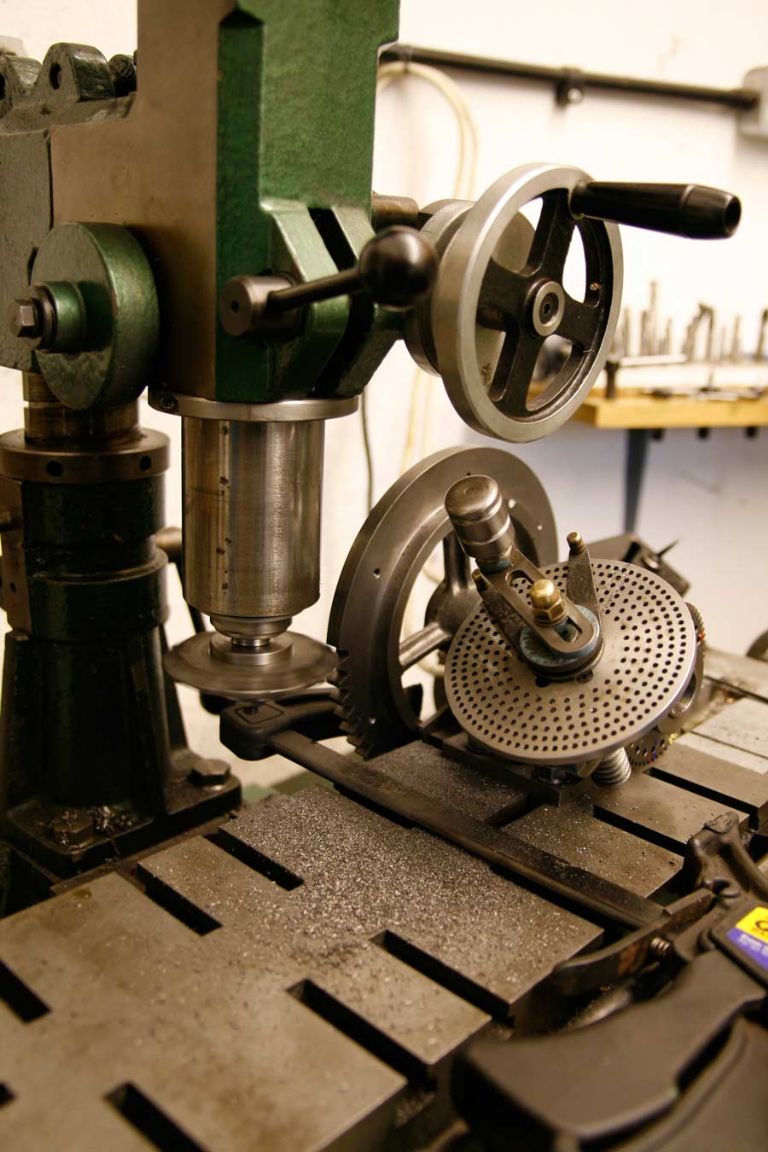 This shows the Dore Westbury being stretched (nearly) to the limit on my Little Samson Second motion gear. I had to hang the gear (and final drive gear which is bigger) over the edge, and then used a clamp to hold the gear against the edge of the table. So the dividing head did the dividing and the table took the cutting thrust. I forget how many cutters I bought to do the full range of gears. 3 I think. There is a driving dog in the arbour by the way. Edited By meyrick griffith-jones on 10/12/2009 14:08:48 |
| Bill Dawes | 10/12/2009 21:47:05 |
| 605 forum posts | That's great, thank you very much. Had a look at Tracy Tools website and have sent off for catalogue.
Best regards
Bill Dawes |
| Nigel McBurney 1 | 26/12/2009 22:47:41 |
 1101 forum posts 3 photos | Hi words of warning,The majority of gear cutters that you will come across either have a pressure angle of fourteen and a half degrees or twenty degrees,common practice for at least the last fifty years is to use twenty degrees and usually this is engraved or etched on the gear,a lot of cutters available are unmarked and others have fourteen and a half degrees etched on them and there are still a lot of them around at dealers and auto jumbles,it is of course good practice to mesh gears which have been cut with cutters having the same pressure angle.So specify when purchasing that cutters must have twenty degrees p/a etched on them,I also understand that a lot of lathe change gears continued to use fourteen and a half p/a long after it went out of common use.when cutting on small lathe/mill set ups it is best to take two cuts on steel or cast on dp gears up to 12 dp.first cut two thirds of gear tooth depth ,second cut one third of depth. |
| JasonB | 27/12/2009 08:01:42 |
 25215 forum posts 3105 photos 1 articles | In answer to your first question about hobbing cutters then ARC Euro do them.
Another source for involute cutters is RDG
Jason |
| Ian S C | 29/12/2009 05:21:19 |
 7468 forum posts 230 photos | I,v only cut two or three non critical(for accuracy)gears,I used a fly cutter gound by hand,if that worked OK then the correct cutter would be a peice of cake.Ian S C |
| Stub Mandrel | 11/02/2010 22:16:28 |
 4318 forum posts 291 photos 1 articles | I've made single-point cutters using Ivan Law's method. They worked 100%: 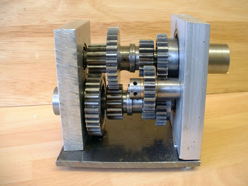 Tom Walshaw (Tubal Cain) was a sceptic and took the approach of hand-filling a cutter to match another gear of the same pitch and similar number of teeth. When I needed a 63-tooth changewheel for metric screwcutting on my lathe, I tried this using a 60-tooth changewheel as a pattern. the result was excellent IMHO: 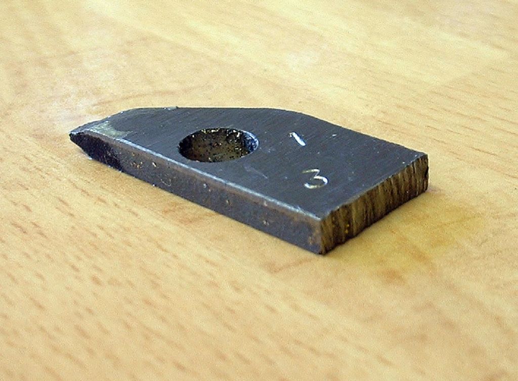 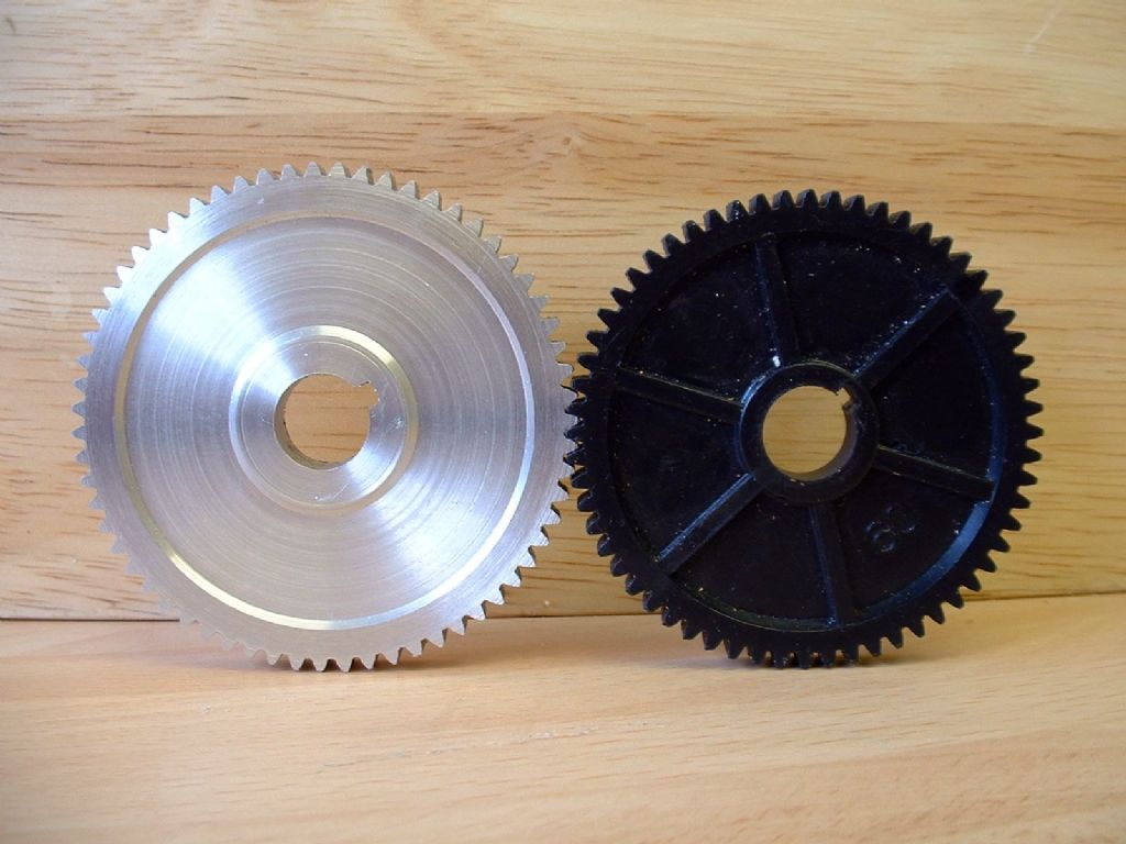 Neil |
| TomK | 11/02/2010 23:07:37 |
| 83 forum posts 23 photos | Bill
If you look at the pictures in my album you will see a myford gear box I am working on
All of the gears were cut on a vertical mill using 20 DP cutters I made on my lathe.
The cutters were made from gauge plate using the button method which is decribed in Ivan Laws book.
|
| Stub Mandrel | 14/02/2010 18:04:29 |
4318 forum posts 291 photos 1 articles | Hi Tom, Those cutters look enviably good. I keep thinking of making a 'Eureka' but your buttons don't look like they were designed for one. What method did you use to relieve them? Neil |
| mgj | 14/02/2010 18:28:17 |
| 1017 forum posts 14 photos | They haven't been form relieved have they ? |
| TomK | 14/02/2010 20:51:26 |
| 83 forum posts 23 photos | Bill
The cutters in the picture are relieved at the bottom is the mandrel that was used to relieve the cutters. The cutters are first turned as blanks using the buttons to ruff out the forrm.
The slots are then cut. The slots are used to time the the cutter on the mandrel. 1 tooth at a time is releived. You must watch the depth you feed each cut to ensure all the teeth are the same from the center.
The method I use for the first tooth is to put marking blue on circumference and relelieve this first when all the blue us removed note the reading and then rotatate each tooth and releive to that depth.
The second part is to set up the buttons and releive to the calculated depth of the form.
one tooth at a time.
I have put up 2 more pictures of the releiving mandrel that may help you.
One more point the diameter of the cutter is important, when relieving you must make sure that the tool does not foul the next tooth. |
| Stub Mandrel | 14/02/2010 21:51:47 |
4318 forum posts 291 photos 1 articles | Thanks Tom, I'll have to try that. What diameter cutters do you use? Neil |
| TomK | 14/02/2010 21:59:22 |
| 83 forum posts 23 photos | Neil Sorry I put Bills name on that reply.
The relieving mandrel I used was designed for 2 inch (50 mm) cutters.
This link takes you to the information to produce gear cutters using the method I used
Tom Edited By TomK on 14/02/2010 22:17:34 |
| mgj | 14/02/2010 22:16:27 |
| 1017 forum posts 14 photos | Tom my apologies- thats very neat - by how many thou has each tooth been relieved. |
| TomK | 14/02/2010 22:38:01 |
| 83 forum posts 23 photos | Meyrick
I checked the dimesion on the cad drawings I did for this and it shows that on the cutters I made from the cutting edge to the trailing edge of the tooth is 0.021 inch clear.
I used the cad rotating fuction to check my dimesions and it shows that the tooth clearance is ok. When using the cutters there is no sign of rubbing on the cutters.
I have added a link to my previous post which shows a method of how this type of cutter is made. I just modified it from a 4 to a 5 tooth and used cad to work out the dimensioning
One other point I have only used this mandrel to make 20 dp 2 inch dia cutters I have not checked it out for other DP size cutters
Tom |
| mgj | 15/02/2010 18:09:31 |
| 1017 forum posts 14 photos | no wonder they looked perfectly round - neat job. I was having brain fade, because I thought (without checking the job) you were using the slots to get away without form relieving - on thinnish work. Then I saw the gearbox which looks very nice. |
| calder percival 1 | 20/02/2010 23:14:51 |
| 19 forum posts 1 photos | Be very carefull when buying cutters from people who advertise in the model engineer and other press as a single tooth cutter costs around £180 in the trade and 8 in a set makes for a lot of money, i have bought three cutters in the last couple of years to cut gears and found that one supplied was actually a stubby tooth version sold for the same dp and pressure angle (it went back) the other two left marks up one side of the tooth and upon inspection with a glass were found to be marked on a couple of teeth. I returned both of these aswell but that did not help with the time i lost. |
| James Veitch | 05/03/2010 03:00:39 |
| 16 forum posts | Hello TomK, Thanks for your contributions to this thread, I've found them interesting and helpful, however I have a question you might be able to help me with. You make reference to two sources: "Gears and Gear Cutting", by Ivan Law and the web article at metalwebnews.com, "Cutting Involute Gears with Form Tools" by John Stevenson. On page 114 of Law's book and in the Stevenson article there is a table to calculate dimensions for the cutting tool. Both authors claim their tables are for DP 1 and a Pressure angle of 20 degrees. Trouble is the two tables do not match. Not even close. So? Can you or anyone else sort this out for me? Thanks in advance, Jim V. |
| John Stevenson | 05/03/2010 12:29:43 |
 5068 forum posts 3 photos | Both sets of tables are correct if used in their entirety and not mixed up. Where the differences are concerned is where the infeed position is calculated from. In Ivan's book [ brilliant book BTW a must read if you are into gear cutting ] he calculates the infeed by touching the outer edge of the button on the blank, moving over to centralise then infeeds the distance in the table. In the web article which was taken from calculations done by Grant in 18 ought plonk, the infeed is taken from a point where both buttons radially touch a blank of known width, [ W ], and then infeeds from this point. It's not easy to spot the differences between the two methods and this causes the tables to be different. However if you drawn these out in CAD and overlay them, the differences are minute and both follow very closely a precise CAD drawn involute. John S. Edited By John Stevenson on 05/03/2010 12:30:35 |
| TomK | 05/03/2010 21:48:02 |
| 83 forum posts 23 photos | James
There is nothing I could add to John Stevenson answer. Just do as John says and only use 1 table and don't mix them.
TomK |
Please login to post a reply.
Magazine Locator
Want the latest issue of Model Engineer or Model Engineers' Workshop? Use our magazine locator links to find your nearest stockist!
Sign up to our Newsletter
Sign up to our newsletter and get a free digital issue.
You can unsubscribe at anytime. View our privacy policy at www.mortons.co.uk/privacy
Latest Forum Posts
- *Oct 2023: FORUM MIGRATION TIMELINE*
05/10/2023 07:57:11 - Making ER11 collet chuck
05/10/2023 07:56:24 - What did you do today? 2023
05/10/2023 07:25:01 - Orrery
05/10/2023 06:00:41 - Wera hand-tools
05/10/2023 05:47:07 - New member
05/10/2023 04:40:11 - Problems with external pot on at1 vfd
05/10/2023 00:06:32 - Drain plug
04/10/2023 23:36:17 - digi phase converter for 10 machines.....
04/10/2023 23:13:48 - Winter Storage Of Locomotives
04/10/2023 21:02:11 - More Latest Posts...
- View All Topics
Support Our Partners


Shopping Partners
Subscription Offer

Latest "For Sale" Ads
- Reeves** - Rebuilt Royal Scot by Martin Evans
by John Broughton
£300.00 - BRITANNIA 5" GAUGE James Perrier
by Jon Seabright 1
£2,500.00 - Drill Grinder - for restoration
by Nigel Graham 2
£0.00 - WARCO WM18 MILLING MACHINE
by Alex Chudley
£1,200.00 - MYFORD SUPER 7 LATHE
by Alex Chudley
£2,000.00 - More "For Sale" Ads...
Latest "Wanted" Ads
- D1-3 backplate
by Michael Horley
Price Not Specified - fixed steady for a Colchester bantam mark1 800
by George Jervis
Price Not Specified - lbsc pansy
by JACK SIDEBOTHAM
Price Not Specified - Pratt Burnerd multifit chuck key.
by Tim Riome
Price Not Specified - BANDSAW BLADE WELDER
by HUGH
Price Not Specified - More "Wanted" Ads...
Get In Touch!
Do you want to contact the Model Engineer and Model Engineers' Workshop team?
You can contact us by phone, mail or email about the magazines including becoming a contributor, submitting reader's letters or making queries about articles. You can also get in touch about this website, advertising or other general issues.
Click THIS LINK for full contact details.
For subscription issues please see THIS LINK.
Digital Back Issues


Donate

 Register
 Log-in
Model Engineer Magazine
- Percival Marshall
- M.E. History
- LittleLEC
- M.E. Clock

ME Workshop
- An Adcock
- & Shipley
- Horizontal
- Mill

Subscribe Now
- Great savings
- Delivered to your door

Pre-order your copy!
- Delivered to your doorstep!
- Free UK delivery!
All Forum Topics > Workshop Techniques > Gear milling