Forum sponsored by:

Glass Drip-oiler Design / Manufacture Advice
| Dr_GMJN | 23/08/2022 21:32:57 |
 1602 forum posts | All, I'm building a Princess Royal mill engine: |
| Nigel Graham 2 | 23/08/2022 22:29:54 |
| 3293 forum posts 112 photos | 'Araldite' is no less prototypical for a Victorian or Edwardian style engine then acrylic! So its use is fine, as long as it's invisible inside the joint. No reason why you can't use a needle-valve. In original practice the oilers were either of that pattern or used worsted trimmings acting as wicks with a syphonic action, but the lubricator body was often of steel or brass. The operating-manuals of the time warned to lift the trimmings when the engine was to be closed for a while, so as not to waste oil. Nor indeed, why the innards can't be dummy fittings or non-existent, with the body of the oiler being basically a good-looking funnel to feed the bearing a few drops of oil directly from a can at the start of the running session. A model engine like this is rarely run for long periods, and exerts very low forces on its bearing surfaces, so oiling like that with a good quality lubricating oil will keep it happy for some hours. I'd use the sort of oils used for lubricating lathe slides etc., rather than motor-car oil. ' What I would say though, is make the "glass" shorter to look right. It is normally of a height about equal to its diameter, and the whole unit not much higher and quite compact. The example in your photo of it on the journal, is out of proportion with itself and the bearing. |
| bernard towers | 23/08/2022 23:08:43 |
| 1221 forum posts 161 photos | you could possibly use glass from an automotive fuse. |
| Ramon Wilson | 23/08/2022 23:24:20 |
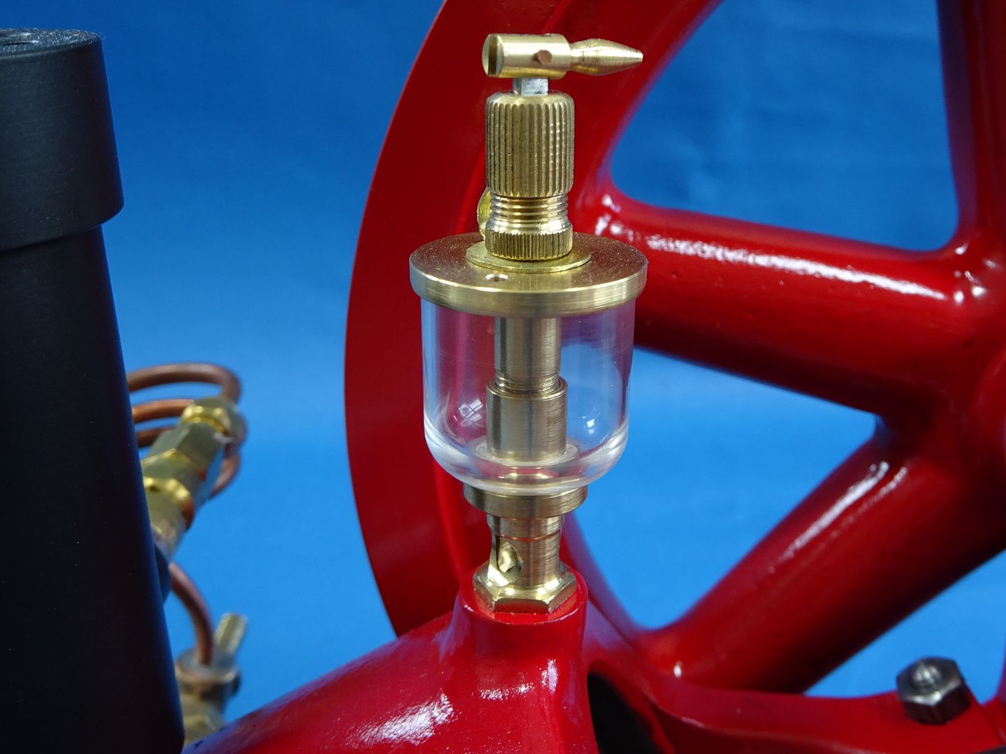
 1655 forum posts 617 photos | Hi Doc, No I wouldn't say you are overthinking this but would agree with Nigel that as you have them they appear rather tall. However, when you look at images of engines or those in museums there is an absolute myriad of design of oilers to choose from so you can pretty much pick and choose. Here are some pics from mine made for the Waller engine. I don't 'turn' the 'glass' merely slide it on a piece of ali turned to suit as a mandrel and just part it off using a sharp pointed tool. This gives a tapered edge where the glue can form a seal. I use the thick super glue, the thin can create fogging in the glass (same as on a canopy)
The bottoms can be threaded but I turned a fine taper on these so no pressure is put on the glass in a turning movement when removing
Some of the other oilers made for secondary shafting etc
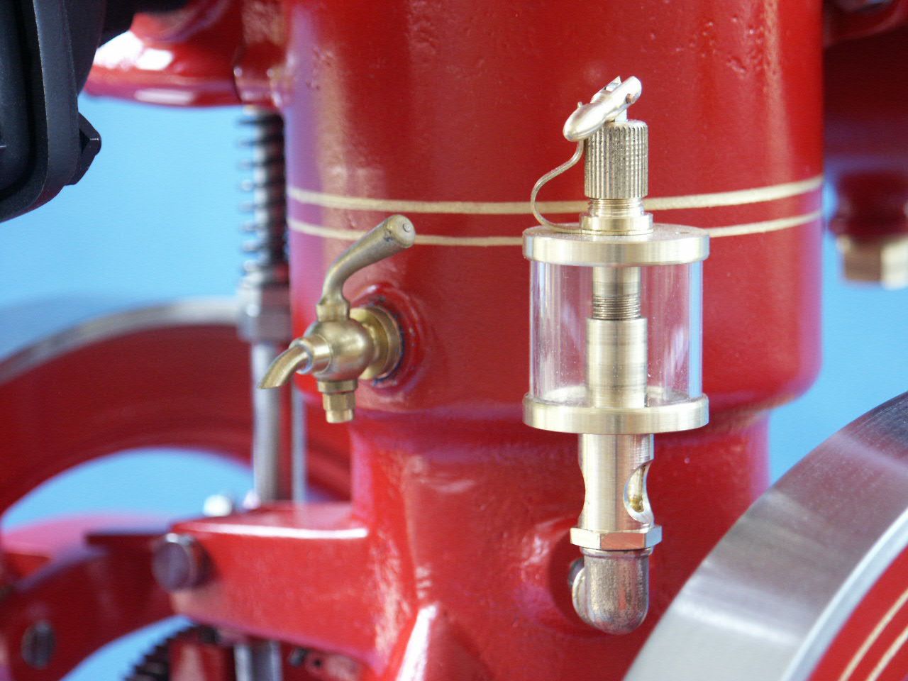
This is the main on the Waller pedestal bearing
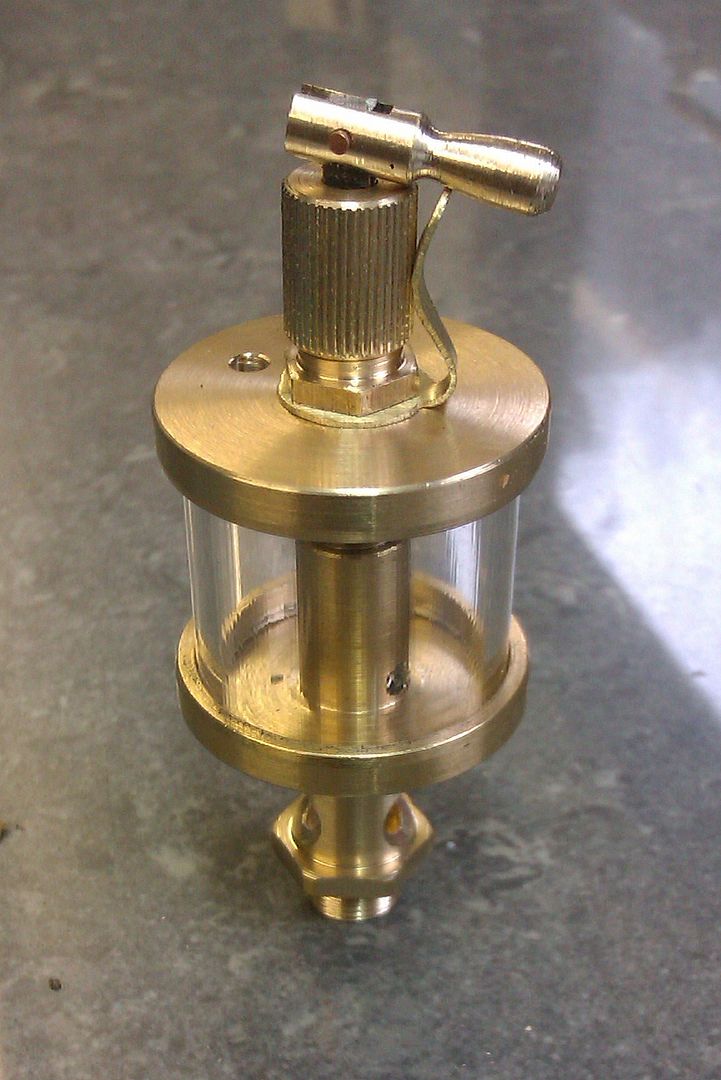
And these are the very first made on my Twin Vic
That should give you some more ideas but as said you are on the right track, just cut the length down a bit. Best - R |
| Paul Kemp | 24/08/2022 01:05:45 |
| 798 forum posts 27 photos | Wouldn’t a drip feed oiler normally have a small sight glass below the reservoir so you can set the feed rate? Ie drips per minute? I haven’t come across many drip feed lubricators outside my myford ones and full size hydrostatic ones on loco’s and they all have sight glasses to set the rate. Paul. |
| JasonB | 24/08/2022 07:17:59 |
 25215 forum posts 3105 photos 1 articles | Full size use glass tube with no spigots which Ramon's tube replicates, the top and bottom have a lip that just overhangs the glass. If you do make from acrylic rather than thin wall tube then you can also shape the glass, there were some nice designs about. They were sealed with cork washers but that is because they had a vertical centre section and the top could be screwed on to apply pressure to the cork. At your scale that can't be done but I do them that way on the hit & miss engines. Also if just sticking them together don't get carried away screwing down a needle as it's likely to pop them apart. Full size and large models use a cam type action much like a bicycle axle quick release that lifts the adjustable needle to open and close the flow with just a light spring pressure to hold the needle into the hole when closed. Full size also have a vent and or filler hole so you don't upset the needle setting trying to fill through that. As Paul says many had an open or glass enclosed neck with cutouts so you could actually see the drips, probably too small to get the glass in but a shaped neck and cross hole could just about be squeezed in if wanted. At 1/3rd scale you can get a bit more detail into them
Edited By JasonB on 24/08/2022 07:21:09 |
| Ramon Wilson | 24/08/2022 08:20:27 |
1655 forum posts 617 photos | Nice work as usual Jason but hard if not nigh on impossible to replicate in Docs much smaller scale especially the lower sight area if you want it to actually work. The flip over lifter would be too - good looking oiler though I've tried to do this Paul but its not worth it at this scale as the dimensions are so small the oil does not move so it's a simple replication at best from a metering point of view. Bernard, though real glass can be used it's fraught with difficulties in cutting accurately and cleanly piece to piece. Besides the constant breakage the pieces of broken glass become an issue too and the wall thickness makes for small volume. The clear plastic tube is so much better from all aspects on these oilers. Jason, I doubt very much if the joint is properly glued the needle screw would have that much jacking force - it's only screwed down with the slightest of force between finger and thumb - never had it happen so far though a clumsy movement of my hand once knocked the glass and the top off one. If that happens clean the traces of super glue off as CA does not like sticking to itself that well. |
| JasonB | 24/08/2022 09:07:11 |
25215 forum posts 3105 photos 1 articles | Yes hard to do in the smaller sizes ( though expect someone has) but I was trying to show Doc what the full size looked like and then upto him how to scale it down both for looks and practicality. I've done similar to you where needed as well as open cups, cups with lids (screwed or pushfit) cups with cocks for cylinders, fat pots and also several where the cap has a cast box or trough to put the oil in agan with and without covers. remote boxes plumbed in with copper pipe, etc So many ways to skin the cat but you just need to find the right one for the job. |
| noel shelley | 24/08/2022 09:37:58 |
| 2308 forum posts 33 photos | CT 1 is a sealer and adhesive, and the clear is just that, crystal clear ! It's a bit like silicon but is much thicker when hard and sticks to almost anything - even wet surfaces ! If the cartridge is kept sealead when not in use it has a good shelf life. It is not cheap at about £15 a cartridge but has so many uses. Noel. |
| Dr_GMJN | 24/08/2022 09:44:31 |
1602 forum posts | Thanks all, very helpful. I'll stick with the parallel tube, and the spigot location method because it gives a good shear area for the Araldite to grip. I tried Araldite last night, and this morning the assembly is rock solid. I'll turn down the centre portion of the 'glass' slightly and polish it back clear, to give the impression of lipped caps (the O/D is currently a bit oval anyway, plus the wall thickness is a bit thick, so all good). I'll reduce the glass length to 6mm, flatten the upper cap a bit, and add fill and vent holes. I'll also re-design the necked part at the bottom slightly, cross-drill it, push a tight fitting drill smeared with vaseline down the oil hole, and fill the cross-holes with optically clear Araldite to form the sight glasses. What is the best way to form the knurled adjuster tops? Do I need a special knurling tool? I've got a crosshatch tool, but it's a bit dodgy. Thanks all.
|
| Andy_G | 24/08/2022 09:51:23 |
 260 forum posts | I made this one (for my hit & miss engine) using a test-tube for the 'glass'
It all "works" but the nozzle doesn't drip nicely - the whole thing is just too small to allow an oil drop to develop without touching the sides, so once the initial drop has formed, it wets to the side of the sight hole and the oil just wicks down the inside (it serves its purpose though). The bottom part screws on to hold the glass in place inside lips on the top and bottom covers, and the joint is sealed with Araldite. There's a small hole in the top cover that acts as a vent and is big enough to fill / empty the lubricator using a hypodermic needle.
Gratuitous picture:
|
| Nigel McBurney 1 | 24/08/2022 09:56:24 |
 1101 forum posts 3 photos | The best oiler which would look neat and realistic on a steam engine would be improve the plain brass oiler shown in the initial set of photos of this thread, a brass turned oiler with a central tube and a single strand of pure natural knitting wool with no synthetics, then machine up a brass cap which has lip to fit over the oiler body,plain fit ie not threaded ensure the central tube does not come up to the top of the oiler or the wool will get squashed and not feed the oil. a small hole in the cap will let air in to allow the oil to flow. If such an oiler is used on a big end or eccentric the the cap is threaded to prevent it flying off.if the oiler is made in a really small scale then the wick feed may not work in this case do not use a central tube just fill the oiler half full of wool to slow the flow of oiler. the disadvantage of wick feed oilers the only way to see if it works is to remove the cap to see if the oil level is going down. The sight feed oiler with the large glass to hold the oil,a needle valve to control the oil,and the lower small glass to view the rate of oil flow is far more common on internal combustion engines. full size I/c engines generally run faster than steam engines and regulation of the oil supply is more critical to prevent seizure,and somewhat affected by the weather,on a hot day the oil flow is far faster and needs slowing down. Looking at the 4 volumes of DK Clarks the steam engine written about 125 years ago,with extremely fine detailed dwgs of steam engines of all types ,the general crank lubrication for engines of the type the Stuarts were modelled on was for an oil pocket to be cast in the top bearing shell with a oil feed tube and syphon wick.Very efficient in use and low cost,all the cap casting required was was a drilled hole to feed oil and hold the syphon tube plus a cap possibly just cast with no machining, My 4 hp National and Gardners have this arrangement,Hornsbys used pressed out caps from blued steel, some engines had cast caps with hinges to prevent loss. this avoided the manufacturing cost of a separate brass oiler with the easily broken glass parts,plus possible theft by the brass thieves. And of course the the syphon has the additional advantage that the wick acts as a filter to ensure clean oil gets to the bearing ,the best glass sight feed oiler have brass gauze to filter larger dirt particles out of the oil but not as good as a wick plus for full size engines such as portables the cast in pocket with cap is far more waterproof when on a winters day of thrashing out in the rain, I have a dozen full size stationary 1/c engines and on some rain water easily get into the oil. For lubrication from the smallest a Stuart 600 to a Hornsby I use Halfords 10/40 multigrade semi synthetic and find it provides far better lubrication than straight mineral oil specified for industrial use,and veteran cars. Castrol is bast but nowadays its harder to find and purchase,cannot even get Castrol grease in Halfords. |
| Dr_GMJN | 24/08/2022 11:17:38 |
1602 forum posts | Thanks both. Andy - the sight glass on mine would purely be a visual feature - it would immediately get full of oil, but I’m not too concerned about that so long as oil gets to the bearings. The wick idea might be good for the big ends, but I guess the plain Stuart type with a cap would suffice (without an actual wick)? |
| JasonB | 24/08/2022 11:26:59 |
25215 forum posts 3105 photos 1 articles | Posted by Dr_GMJN on 24/08/2022 09:44:31:
What is the best way to form the knurled adjuster tops? Do I need a special knurling tool? I've got a crosshatch tool, but it's a bit dodgy. The first straight knurls that I did before buying a set of straight wheels were done by grinding a point onto the end of an old ctr drill or HSS cutter and holding that stationary in the mill while the work was indexed round in the rotary table and then traversed back and forth for each cut, took a while but came out OK. But do bear in mind the scale, at 1/18th you want a very fine knurl
|
| Ramon Wilson | 24/08/2022 12:21:00 |
1655 forum posts 617 photos | Doc, Though Nigel has it right with using wicks none of the small oilers on my engines have had any fitted so far. That said the oil boxes on the Marine Compound main bearings have been set up so with an inner tubing for the oil to wick into. You can also get some practice in on shaping on the lathe as well as the mill as Jason suggests but you do have to have a means of division. I use a very fine knurl mounted in a simple push type holder. This is fine for brass and works well if the knurl is presented at a fine angle, cutting/forming on the rear edge, and moved along and back over the workpiece.
That second Knurl is surplus to requirements so if you would like to make a similar tool you are welcome to it. Send me a PM if so
Here are a few more oilers made using plastic tubing on the Double Diagonal engine which may give food for thought
These are quite old and have developed an oily patina but that disappears once full Like Andy my very early attempts to make an oiler were using 'proper glass' in the form of sight tube glass, cutting it isn't so much the issue but doing it in very small lengths was and the breakage rate was high so that's when I looked for an alternative and began using the protectors off artists paint brushes. At first these were from my own but when I asked at the local art shop if they sold them they presented me with a box full of redundant ones and just said help yourself. Machining them from solid in acrylic is just as good but with tubes you don't have to polish the insides. Hope that's of use - R Edited By Ramon Wilson on 24/08/2022 12:23:14 |
| bernard towers | 24/08/2022 12:24:58 |
| 1221 forum posts 161 photos | For small straight knurls just put a pointed lathe tool on its side and cut the divisions, it’s easy in brass |
| Andy_G | 24/08/2022 12:45:20 |
260 forum posts | Posted by Dr_GMJN on 24/08/2022 11:17:38:
Thanks both. Andy - the sight glass on mine would purely be a visual feature - it would immediately get full of oil, but I’m not too concerned about that so long as oil gets to the bearings. The wick idea might be good for the big ends, but I guess the plain Stuart type with a cap would suffice (without an actual wick)? Thanks. My crank bearing oilers are plain blass cups with push-fit lids (held in place by a small o-ring). I put a wad of wool inside to hold onto the oil a bit longer (not in the photos). Maybe not 'prototypical enough' for the job in hand though:
Lid removed from the RH oiler and resting upside down on top of the big end.
Edited By Andy_G on 24/08/2022 12:46:48 |


Please login to post a reply.
Magazine Locator
Want the latest issue of Model Engineer or Model Engineers' Workshop? Use our magazine locator links to find your nearest stockist!
Sign up to our Newsletter
Sign up to our newsletter and get a free digital issue.
You can unsubscribe at anytime. View our privacy policy at www.mortons.co.uk/privacy
Latest Forum Posts
- *Oct 2023: FORUM MIGRATION TIMELINE*
05/10/2023 07:57:11 - Making ER11 collet chuck
05/10/2023 07:56:24 - What did you do today? 2023
05/10/2023 07:25:01 - Orrery
05/10/2023 06:00:41 - Wera hand-tools
05/10/2023 05:47:07 - New member
05/10/2023 04:40:11 - Problems with external pot on at1 vfd
05/10/2023 00:06:32 - Drain plug
04/10/2023 23:36:17 - digi phase converter for 10 machines.....
04/10/2023 23:13:48 - Winter Storage Of Locomotives
04/10/2023 21:02:11 - More Latest Posts...
- View All Topics
Support Our Partners


Shopping Partners
Subscription Offer

Latest "For Sale" Ads
- Reeves** - Rebuilt Royal Scot by Martin Evans
by John Broughton
£300.00 - BRITANNIA 5" GAUGE James Perrier
by Jon Seabright 1
£2,500.00 - Drill Grinder - for restoration
by Nigel Graham 2
£0.00 - WARCO WM18 MILLING MACHINE
by Alex Chudley
£1,200.00 - MYFORD SUPER 7 LATHE
by Alex Chudley
£2,000.00 - More "For Sale" Ads...
Latest "Wanted" Ads
- D1-3 backplate
by Michael Horley
Price Not Specified - fixed steady for a Colchester bantam mark1 800
by George Jervis
Price Not Specified - lbsc pansy
by JACK SIDEBOTHAM
Price Not Specified - Pratt Burnerd multifit chuck key.
by Tim Riome
Price Not Specified - BANDSAW BLADE WELDER
by HUGH
Price Not Specified - More "Wanted" Ads...
Get In Touch!
Do you want to contact the Model Engineer and Model Engineers' Workshop team?
You can contact us by phone, mail or email about the magazines including becoming a contributor, submitting reader's letters or making queries about articles. You can also get in touch about this website, advertising or other general issues.
Click THIS LINK for full contact details.
For subscription issues please see THIS LINK.
Digital Back Issues


Donate

 Register
 Log-in
Model Engineer Magazine
- Percival Marshall
- M.E. History
- LittleLEC
- M.E. Clock

ME Workshop
- An Adcock
- & Shipley
- Horizontal
- Mill

Subscribe Now
- Great savings
- Delivered to your door

Pre-order your copy!
- Delivered to your doorstep!
- Free UK delivery!
All Forum Topics > General Questions > Glass Drip-oiler Design / Manufacture Advice