Forum sponsored by:

Turning (approximating) a Domed Surface
| Dr_GMJN | 27/09/2021 16:30:39 |
 1602 forum posts | All, I need to turn a dome shape for a pair of cylinder caps. Similar to a typical smokebox door kind of thing. I've heard of using co-ordinates on the cross and top slide, presumably in conjunction with turning the top-slide to different tangent angles. Can anyone tell me the procedure, and also what's the best way of smoothing the facets generated? I want them to be identical. Material is cast iron. Radius of the dome is about 50mm, and the diameter of the domed disc is about 25mm Thanks. |
| John Hinkley | 27/09/2021 17:37:50 |
 1545 forum posts 484 photos | That size of dome lends itself ideally to a radius turning attachment. John |
| John Haine | 27/09/2021 17:43:28 |
| 5563 forum posts 322 photos | ...or CNC turning... |
| Clive Brown 1 | 27/09/2021 17:50:43 |
| 1050 forum posts 56 photos | I would do that type of turning with a hand-held graver. Mine is a length of 1/4" sq. hss mounted in a file handle. A hand-turning rest is required. Mine is usually a piece of square or rectangular BMS suitably positioned in the tool-post. The graver is sharpened by grinding its end-face flat at about 45 deg. Works very well on most materials. |
| John Haine | 27/09/2021 17:51:37 |
| 5563 forum posts 322 photos | Or a Turnado - type attachment for the lathe? Approximate in facets them smooth by hand turning? |
| JasonB | 27/09/2021 18:34:10 |
 25215 forum posts 3105 photos 1 articles | I tend to rough them out with combined hand twiddling of the cross and top slide handwheels to get a shape that looks pleasing to the eye and then finish with a small handheld scraper. If you want them both identical then work out some co-ordinates in CAD and use those with a small round nosed tool then blend by hand |
| Dr_GMJN | 27/09/2021 18:41:31 |
1602 forum posts | Thanks all. Jason - I’m not sure what the co-ordinated would do.Do you mean drive, say, a 0.8 radius tool to a series of locations, and blend the remaining peaks? I’d imagine I’d need dozens of positions to do that? Or do you move the tool to subsequent locations by moving first in x, then in y to give steps, and blend the steps? It should probably be obvious but I can’t visualise the process. |
| John P | 27/09/2021 18:44:59 |
| 451 forum posts 268 photos | Posted by Dr_GMJN 27/09/2021 16:30:39 All, I need to turn a dome shape for a pair of cylinder caps. Similar to a typical I've heard of using co-ordinates on the cross and top slide, Material is cast iron. Radius of the dome is about 50mm, and Thanks.
John |
| Clive Brown 1 | 27/09/2021 18:48:11 |
| 1050 forum posts 56 photos | I made this cover recently with the hand-graver I described. Pretty much free-hand and took only a few minutes. A bit more care perhaps if 2 identical domes were wanted. Brass in this case, but CI would be much the same. |
| DC31k | 27/09/2021 18:51:26 |
| 1186 forum posts 11 photos | It might be worth drawing or visualising what he wants to do before making too many more suggestions. Using the 50mm radius and 25mm diameter mentioned in the first post, the curve pokes out about 1.6mm at its centre. |
| John P | 27/09/2021 18:52:30 |
| 451 forum posts 268 photos | Just found this photo re my last post showing set up for turning small radius. John |
| bernard towers | 27/09/2021 19:05:39 |
| 1221 forum posts 161 photos | John p , just beat me to I have videos but the site won’t let me upload them. Easy to make and set up and fascinating to watch especially if you have pcf. Dr_GMJN if you want videos message or mail me. |
| JasonB | 27/09/2021 19:18:26 |
25215 forum posts 3105 photos 1 articles | Posted by Dr_GMJN on 27/09/2021 18:41:31:
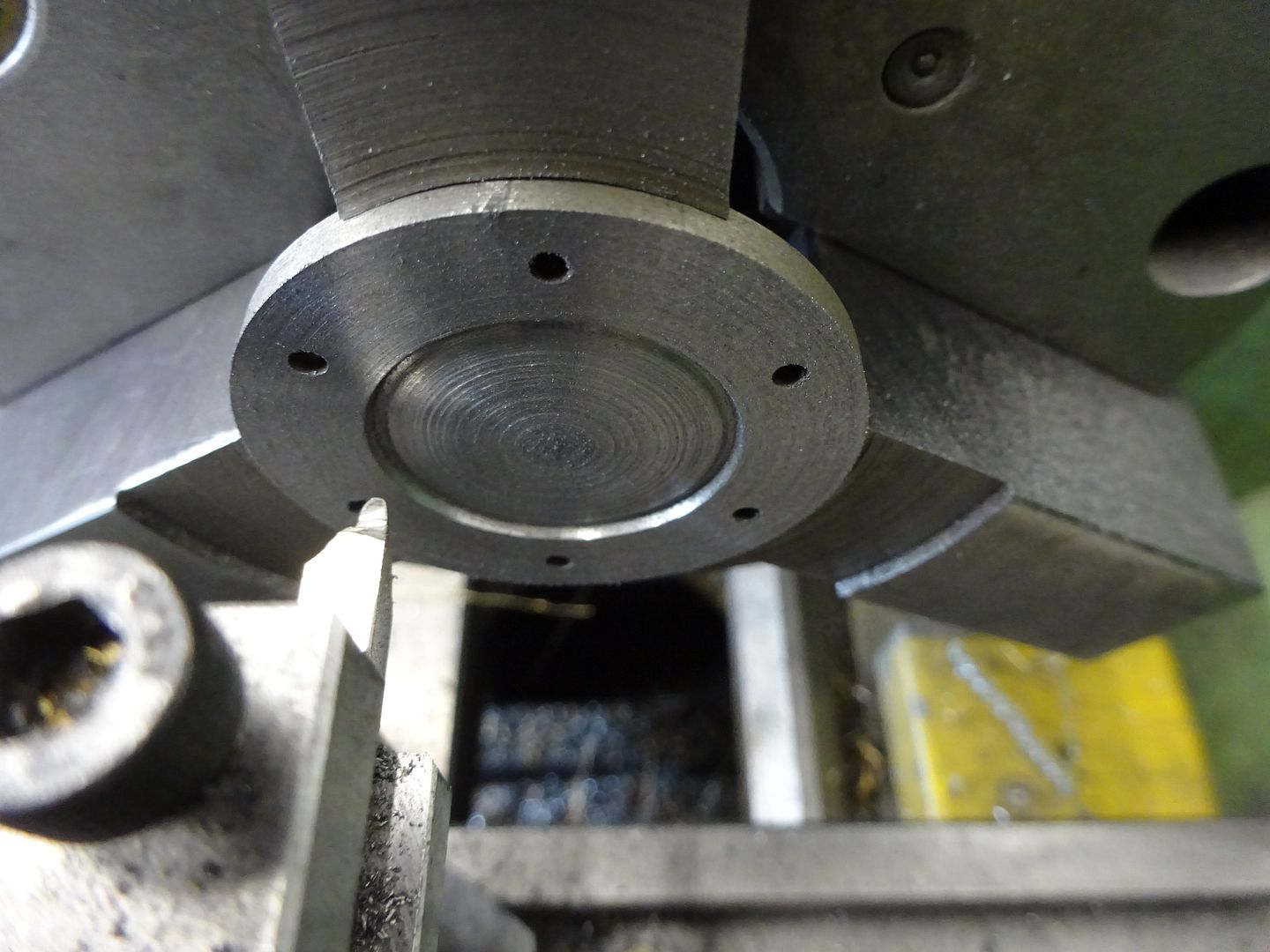
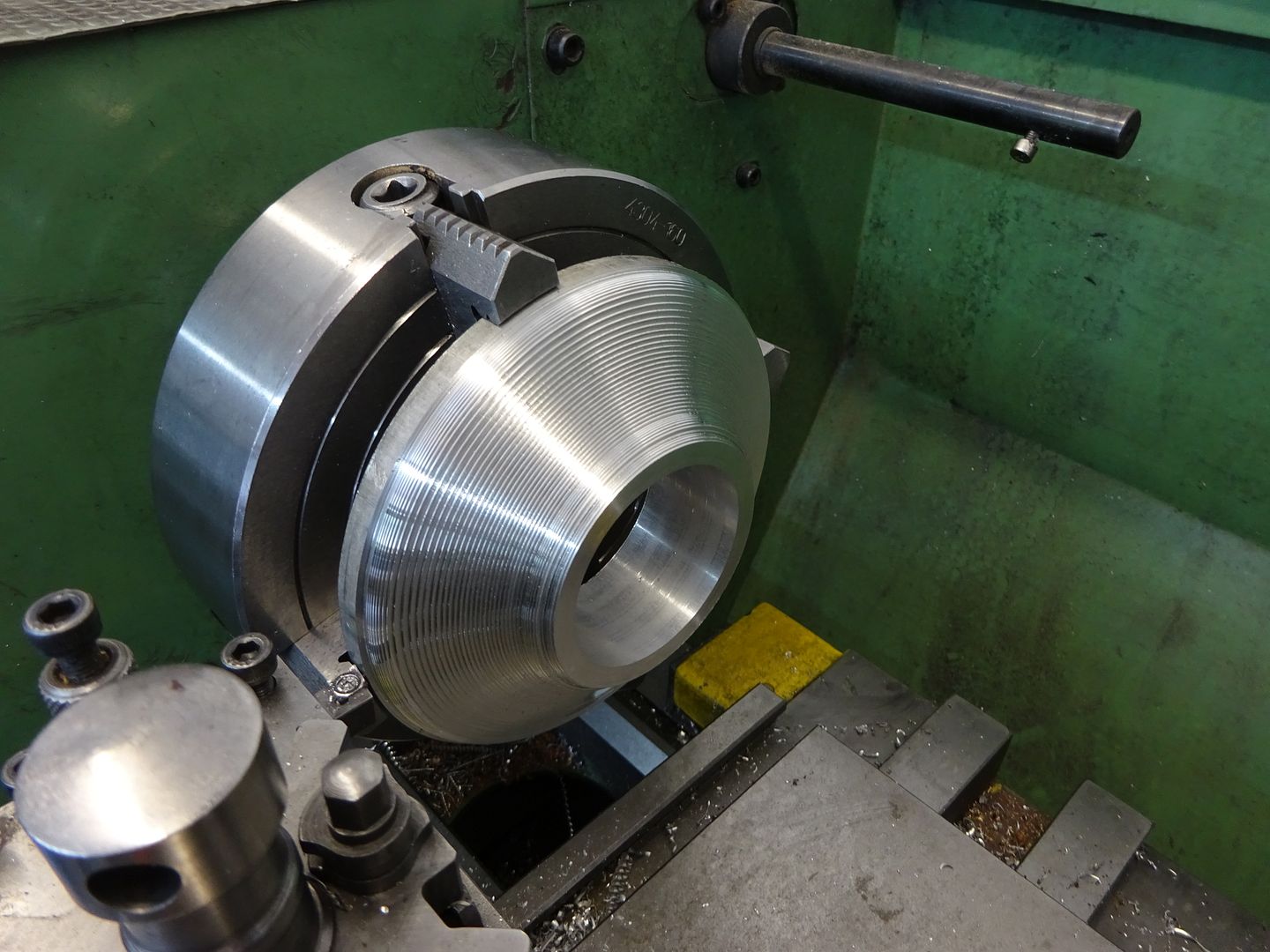
Jason - I’m not sure what the co-ordinated would do.Do you mean drive, say, a 0.8 radius tool to a series of locations, and blend the remaining peaks? I’d imagine I’d need dozens of positions to do that? If you draw a section through the cylinder end cover and then draw a line to follow the profile set away by the radius of the tool's tip you can then pick co-ordinates along that line. For a relatively flat dome like you need the cross slide can be moved a convinient amount each time say 0.020" or 0.030" so draw a series of lines at your chosen spacing and then measure offsets for each one. I have taken the point of contact in the ctr to be 0,0 and you can see the further I bring the tool away from ctr with the cross slide the deeper each plunge cut is. eg at 6.5mm from the middle I'm plunging in 0.491mm.
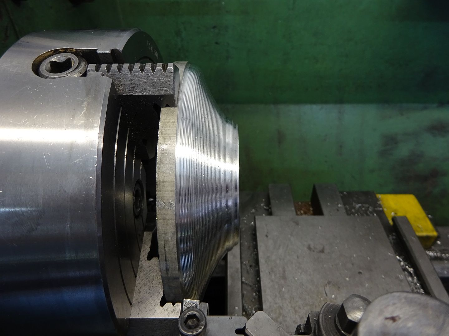
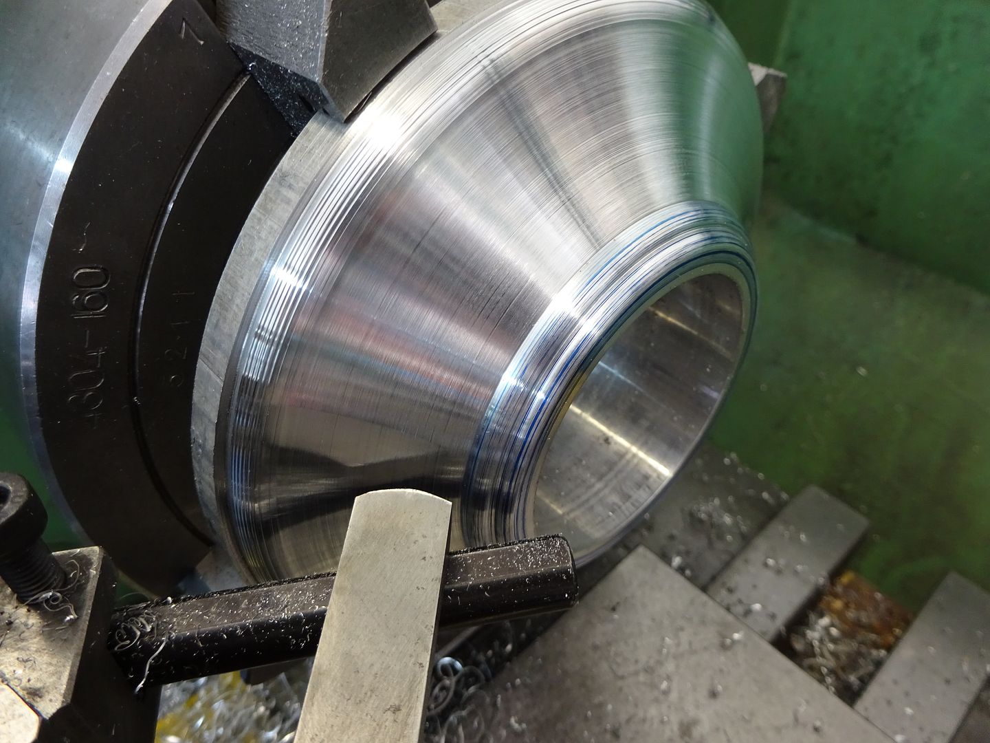
You then just blend in the high spots to give you this
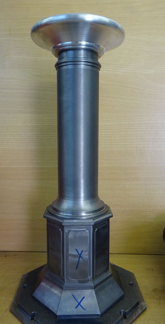
It works with any shape such as this decorative column capital
Edited By JasonB on 27/09/2021 19:18:58 |
| JasonB | 27/09/2021 19:48:15 |
25215 forum posts 3105 photos 1 articles | For the benefit of DC31K and anyone else who can't work out what is needed here is a section through the cylinder cover, it's the domed cream coloured surface that needs to be machined
|
| Andrew Johnston | 27/09/2021 20:21:10 |
 7061 forum posts 719 photos | An alternative to the rather neat rod method is to follow a template. Here's a smokebox door being machined using an automated (hydraulic) follower:
The template could just as easily be followed by hand manipulation of the slides. The method has the advantage of repeatability. Andrew |
| Ron Laden | 27/09/2021 20:35:46 |
 2320 forum posts 452 photos | I have used the guide rod method a few times, its simple, quick to do and works a treat. A picture below of the convex face I turned on the class 22 buffers. Ron
|
| Dr_GMJN | 27/09/2021 21:18:31 |
1602 forum posts | Thanks everyone - there’s a lot of interesting info here. I like the guide rod idea, but having looked at Jason’s sketch I wonder if an elliptical arc would look better. Ill sketch some geometry out and the decide between co-ordinates or guide rod. In fact the guide rod looks too cool an idea to ignore - I’m going to try it anyway on some scrap. Thanks again all. |
| John Reese | 27/09/2021 21:45:49 |
 1071 forum posts | A comment on the radius rod (guide rod) method. The rod needs to be parallel with the bed when the cutter is on the spindle axis (centered on the work.. |
| Ron Laden | 28/09/2021 05:17:27 |
2320 forum posts 452 photos | Thanks John, that is true if you are working to a given radius (I wasn't on the buffers) then the rod needs to be the length of that radius dimension and set parallel to the bed. Also with a 50mm radius you can see that the rod would be too short to run between the head and the cross slide so a fixed extension is needed as seen in the John P picture. Thinking about it the extension doesn't have to come off the head if it's easier then something clamped across the bed would also work. Ron Edited By Ron Laden on 28/09/2021 05:20:39 |
| Andy_G | 28/09/2021 08:53:30 |
 260 forum posts | Posted by Dr_GMJN on 27/09/2021 18:41:31: Do you mean drive, say, a 0.8 radius tool to a series of locations, and blend the remaining peaks? I’d imagine I’d need dozens of positions to do that? Or do you move the tool to subsequent locations by moving first in x, then in y to give steps, and blend the steps? I stepped in Z by 0.2mm and turned to calculated X positions to generate the radiussed section at the right hand end of this part. Because my cross slide has a 1.25mm pitch, I converted my X coordinates to full turns & vernier readings to save mental arithmetic & inevitable mistakes during turning! You can see the crib sheet in the background. Very little blending needed with a large radius tool.
I keep meaning to rig up a (manual) template follower, but haven’t got around to it yet. |


Please login to post a reply.
Magazine Locator
Want the latest issue of Model Engineer or Model Engineers' Workshop? Use our magazine locator links to find your nearest stockist!
Sign up to our Newsletter
Sign up to our newsletter and get a free digital issue.
You can unsubscribe at anytime. View our privacy policy at www.mortons.co.uk/privacy
Latest Forum Posts
- hemingway ball turner
04/07/2025 14:40:26 - *Oct 2023: FORUM MIGRATION TIMELINE*
05/10/2023 07:57:11 - Making ER11 collet chuck
05/10/2023 07:56:24 - What did you do today? 2023
05/10/2023 07:25:01 - Orrery
05/10/2023 06:00:41 - Wera hand-tools
05/10/2023 05:47:07 - New member
05/10/2023 04:40:11 - Problems with external pot on at1 vfd
05/10/2023 00:06:32 - Drain plug
04/10/2023 23:36:17 - digi phase converter for 10 machines.....
04/10/2023 23:13:48 - More Latest Posts...
- View All Topics
Support Our Partners


Shopping Partners
Subscription Offer

Latest "For Sale" Ads
- Reeves** - Rebuilt Royal Scot by Martin Evans
by John Broughton
£300.00 - BRITANNIA 5" GAUGE James Perrier
by Jon Seabright 1
£2,500.00 - Drill Grinder - for restoration
by Nigel Graham 2
£0.00 - WARCO WM18 MILLING MACHINE
by Alex Chudley
£1,200.00 - MYFORD SUPER 7 LATHE
by Alex Chudley
£2,000.00 - More "For Sale" Ads...
Latest "Wanted" Ads
- D1-3 backplate
by Michael Horley
Price Not Specified - fixed steady for a Colchester bantam mark1 800
by George Jervis
Price Not Specified - lbsc pansy
by JACK SIDEBOTHAM
Price Not Specified - Pratt Burnerd multifit chuck key.
by Tim Riome
Price Not Specified - BANDSAW BLADE WELDER
by HUGH
Price Not Specified - More "Wanted" Ads...
Get In Touch!
Do you want to contact the Model Engineer and Model Engineers' Workshop team?
You can contact us by phone, mail or email about the magazines including becoming a contributor, submitting reader's letters or making queries about articles. You can also get in touch about this website, advertising or other general issues.
Click THIS LINK for full contact details.
For subscription issues please see THIS LINK.
Digital Back Issues


Donate

 Register
 Log-in
Model Engineer Magazine
- Percival Marshall
- M.E. History
- LittleLEC
- M.E. Clock

ME Workshop
- An Adcock
- & Shipley
- Horizontal
- Mill

Subscribe Now
- Great savings
- Delivered to your door

Pre-order your copy!
- Delivered to your doorstep!
- Free UK delivery!
All Forum Topics > Workshop Techniques > Turning (approximating) a Domed Surface