Forum sponsored by:

Milling Vice clamps
How many do I need?
| Chris V | 23/03/2021 10:54:09 |
 313 forum posts 42 photos | I have a 3" milling vice to use with my Amolco Mill. The vice is the type with holes along each side so I'm going to make some hold down buttons to locate in one hole each side that are then screwed down into tee nuts. Should I be making just two, one for either side? Maybe one spare, or did I read somewhere you should have 3 points of contact which would suggest I need 3? Cheers Chris. |
| Dave Halford | 23/03/2021 11:03:54 |
| 2536 forum posts 24 photos | Be very careful using bolts to clamp anything to the table, it's all to easy to use one too long which is how you break out the table slot. Studs are much safer and any tee nuts should have the thread dinked on the under side to prevent screwing through. Two studs are fine. |
| Emgee | 23/03/2021 11:16:06 |
| 2610 forum posts 312 photos | As Dave says Tee studs are safer in use and can be dedicated to each job, 2 holding points should be sufficient unless you intend to take some heavy cuts in which case best to fit the vice with a fence fitted to to the table to take the extra load. Emgee |
| Journeyman | 23/03/2021 11:37:41 |
 1257 forum posts 264 photos | Two I think will be adequate. Have a look at my ** Milling Vice Clamps ** on Journeyman's Workshop, may or may not help a bit. John |
| Chris V | 23/03/2021 12:40:35 |
313 forum posts 42 photos | Thank you all so much for the prompt replies Dave & Emgee! Yes I am aware about the risks of breaking out the table, but it dosen't hurt to be told again! (-: Journeyman yes those are what I shall be making, I found a drawing online elsewhere but you give a much more detailed guide to making so I shall fine that useful. Looks to be a very interesting website too, don't think I had found that before so thanks again! Chris. |
| not done it yet | 23/03/2021 13:32:53 |
| 7517 forum posts 20 photos | Comments for others reading this thread and considering these types of vise. One may well only have a two hold-down option if the table is imperial - unless one makes off-set clamps.🙂 I bought the type ll vises as sold by ARC. These have slots along the length of the vise and can accommode more clamps if felt necessary (my tables are imperial). I always use two on one side and one on the other (at least) on my three T-Slotted table and two on each side on the Centec as it only has two T-slots. Belt and braces, probably - but better more than too few.🙂 It costs naff-all to make extras, in both materials and time, when making them as a batch. I think I have about ten clamps - mostly made from scrap. The others (if I can find them) are always available if/when I drop one behind a machine. The ones not in use with a vise have come in handy once, so far, for holding down a ~10mm part. Journeyman's type may not be so useful elsewhere. Journeyman's option for fixings is, IMO, the better option - as long as the countersunk set screws are the correct length for the job. With mine, I can use hex or Allen head, as the height will not interfere with parts held in the vise. I would have gone countersunk cap heads if clamp height was an issue. I leave the T-nut and bolt with the clamp, so they don’t get separated, if possible. Journeyman’s fixings are closer to the vise than mine (with hex heads), so marginally better clamping force. |
| John Baron | 23/03/2021 14:35:50 |
 520 forum posts 194 photos | Hi Guys, I also bought one of the type ll vises as sold by ARC. These have slots along the length of the vise and can accommodate more clamps if felt necessary. I mounted mine on a ground flat 12 mm thick plate with four hold downs for the vise and four "T" nuts and studs to hold the plate. I put a register on the bottom so that the vise can be removed and put back in the mill table knowing that it will be dead square. My only criticism of the vise is that I've discovered that the rear jaw is not true vertically. I've only found out recently. The top and front edge is OK as is the slides, however one side is a few thou smaller than the top on one side. I initially I thought that this was a vertical tram error but checking with a square it seems not to be.
|
| HOWARDT | 23/03/2021 15:44:21 |
| 1081 forum posts 39 photos | Place a fixed stop either side of the vice, fitted into the tee slot and pushed up to the side of the vice. This will stop the vice from rotating under a cut, relying purely on friction between the vice and table under clamps is not perfect. Make sure the clamp heels spread the load and don't indent into the table. |
| Journeyman | 23/03/2021 16:18:17 |
1257 forum posts 264 photos | A bit of an aside regarding this type of Precision Tool Vice: I don't believe they are intended for heavy duty milling where a 'proper' milling vice would be the order of the day. They are of course useful on small machines and for small jobs on the larger mills. They are indeed useful for holding work at an angle when used in a larger milling vice. By their very design as you tighten the screw a good portion of the force involved is in fact diverted to pulling the jaw down so if you have really tightened it up, perhaps the work-holding force is only half that which you believe it to be! Just a thought but still a very useful bit of kit. John |
| Chris V | 24/03/2021 09:19:53 |
313 forum posts 42 photos | Well as expected some great advice thank you all. Not done it yet, good point, I am indeed mixing metric & imperial so one button on either side will do me for now. John Baron, what sort of register did you use for your sub base, a couple of pins screwed into the base? Howard, thanks yes a couple of fixed stops will be made also for belt & braces. I hadn't considered the heels of the clamp down buttons marking the table, apart from removing the sharpness Chris. |
| Nick Wheeler | 24/03/2021 11:25:24 |
| 1227 forum posts 101 photos | Posted by Chris V on 24/03/2021 09:19:53:
I hadn't considered the heels of the clamp down buttons marking the table, apart from removing the sharpness
The heels on mine are about 2mm wide and 1 deep. I never considered they might mark the table and after about 16 years, they haven't. I don't want studs and nuts for this sort of clamp as theyget in the way; mine use allen bolts in counterbores. It takes a few seconds to check their length the first time they're used, and shorten them if necessary |
| Mike Poole | 24/03/2021 11:43:31 |
 3676 forum posts 82 photos | Just using 2 clamps seem to leave the chance of a heavy cut moving the vice. Although vices are usually fixed with 2 bolts they are often a very wide flange where the bolt slots are located. With the fixings being so close together I feel the vice could pivot with a heavy cut. Of course I may be over cautious and a lot will depend on the use of the vice. Mike |
| John Baron | 24/03/2021 13:44:25 |
520 forum posts 194 photos | Posted by Chris V on 24/03/2021 09:19:53:
Well as expected some great advice thank you all. John Baron, what sort of register did you use for your sub base, a couple of pins screwed into the base? Hi Chris, No my mill is a Chinese copy of the Optimum, similar to the WM16 and others. I used a shallow slot milled across the bottom of the plate and a length of bar screwed in, it is milled to be just wide enough to drop into the table slots anywhere I choose. The base thickness was simply because I had a piece of precision ground plate of suitable size, and it is a lot harder to distort than thinner plate. It also has the advantage that I can slide the vise to one side and place the rotary table on the mill as well, so I have use of both if I need to. The vise hold downs are machined from square bar and use M6 cap screws in counterbores to secure them. The plate is held down in the usual way with "T" nuts, studs and plates, the plates supported on alloy pillars sitting in the table slots. I can take a picture if you want !
Edited By John Baron on 24/03/2021 13:47:25 |
| Chris V | 24/03/2021 14:03:26 |
313 forum posts 42 photos | Thanks very much John, that's great info, yes a photo would be really good to see too! Chris. |
| Ian Johnson 1 | 24/03/2021 14:21:52 |
| 381 forum posts 102 photos | I had the same problem with clamps denting the table, so I made these in the pic, they are little aluminium blocks machined to the same height as the vice slots, the steel top clamp can be bolted down spreading the load evenly. It'll do until I make better looking one piece clamps.
Weirdly this is a new cast iron longer table which dents easily, softer than aluminium! the old smaller cast iron table didn't dent at all, must be made of tougher stuff! IanJ |
| John Baron | 24/03/2021 16:45:18 |
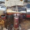
520 forum posts 194 photos | Hi Chris, Guys, There are five pictures, I've put them in an album, so they don't get lost on my computer.
I've very recently spent some time fitting a DRO and doing some maintenance on the mill. The wooden way covers and the aluminium ones at the back are just a couple of new items.
The long hold down studs are M8 with 8 mm thick clamp plates. The other new item is the stop on the vise at the left. The one on the right is just a piece of 4 mm plate that I had kicking about.
These are just close up pictures of the clamps. You can see the 12 mm precision ground plate. Hope these pictures help. Best Regards: BaronJ:
|
| Chris V | 24/03/2021 18:51:41 |
313 forum posts 42 photos | Thanks very much John, yes that clarifies a lot. Plenty for me to think on now! (-: Cheers Chris. |
| Dave Halford | 25/03/2021 17:49:25 |
| 2536 forum posts 24 photos | Posted by Nicholas Wheeler 1 on 24/03/2021 11:25:24:
Posted by Chris V on 24/03/2021 09:19:53:
I hadn't considered the heels of the clamp down buttons marking the table, apart from removing the sharpness
The heels on mine are about 2mm wide and 1 deep. I never considered they might mark the table and after about 16 years, they haven't. I don't understand the need for all the extra complexity involved with this set up and even if the table is made of cheese Johns vise and clamp combo should not need the plate. I would be worrying more about the table humping under the pressure of the tee nuts. |
| Nick Wheeler | 25/03/2021 18:39:03 |
| 1227 forum posts 101 photos | Posted by Dave Halford on 25/03/2021 17:49:25:
Posted by Nicholas Wheeler 1 on 24/03/2021 11:25:24:
Posted by Chris V on 24/03/2021 09:19:53:
I hadn't considered the heels of the clamp down buttons marking the table, apart from removing the sharpness
The heels on mine are about 2mm wide and 1 deep. I never considered they might mark the table and after about 16 years, they haven't. I don't understand the need for all the extra complexity involved with this set up and even if the table is made of cheese Johns vise and clamp combo should not need the plate. I would be worrying more about the table humping under the pressure of the tee nuts. I agree, which is why my vice clamps fit into the holes in the vice pin holes, and clamps directly to the table. |
| John Baron | 25/03/2021 19:47:04 |
520 forum posts 194 photos | Hi Guys, Just for the nay sayers, I can remove and replace my vise without all the hassle of setting it up square again ! Which of course also means that I can move the vise anywhere on the mill table and not have to get the gauges out to set it up square. These vises do not have any grooves or slots for alignment keys. It also prevents the screw from digging into the table when the vise moving jaw isn't quite far enough back ! So thanks for your comments, this system works for me, and that is all that matters.
|


Please login to post a reply.
Magazine Locator
Want the latest issue of Model Engineer or Model Engineers' Workshop? Use our magazine locator links to find your nearest stockist!
Sign up to our Newsletter
Sign up to our newsletter and get a free digital issue.
You can unsubscribe at anytime. View our privacy policy at www.mortons.co.uk/privacy
Latest Forum Posts
- hemingway ball turner
04/07/2025 14:40:26 - *Oct 2023: FORUM MIGRATION TIMELINE*
05/10/2023 07:57:11 - Making ER11 collet chuck
05/10/2023 07:56:24 - What did you do today? 2023
05/10/2023 07:25:01 - Orrery
05/10/2023 06:00:41 - Wera hand-tools
05/10/2023 05:47:07 - New member
05/10/2023 04:40:11 - Problems with external pot on at1 vfd
05/10/2023 00:06:32 - Drain plug
04/10/2023 23:36:17 - digi phase converter for 10 machines.....
04/10/2023 23:13:48 - More Latest Posts...
- View All Topics
Support Our Partners


Shopping Partners
Subscription Offer

Latest "For Sale" Ads
- Reeves** - Rebuilt Royal Scot by Martin Evans
by John Broughton
£300.00 - BRITANNIA 5" GAUGE James Perrier
by Jon Seabright 1
£2,500.00 - Drill Grinder - for restoration
by Nigel Graham 2
£0.00 - WARCO WM18 MILLING MACHINE
by Alex Chudley
£1,200.00 - MYFORD SUPER 7 LATHE
by Alex Chudley
£2,000.00 - More "For Sale" Ads...
Latest "Wanted" Ads
- D1-3 backplate
by Michael Horley
Price Not Specified - fixed steady for a Colchester bantam mark1 800
by George Jervis
Price Not Specified - lbsc pansy
by JACK SIDEBOTHAM
Price Not Specified - Pratt Burnerd multifit chuck key.
by Tim Riome
Price Not Specified - BANDSAW BLADE WELDER
by HUGH
Price Not Specified - More "Wanted" Ads...
Get In Touch!
Do you want to contact the Model Engineer and Model Engineers' Workshop team?
You can contact us by phone, mail or email about the magazines including becoming a contributor, submitting reader's letters or making queries about articles. You can also get in touch about this website, advertising or other general issues.
Click THIS LINK for full contact details.
For subscription issues please see THIS LINK.
Digital Back Issues


Donate

 Register
 Log-in
Model Engineer Magazine
- Percival Marshall
- M.E. History
- LittleLEC
- M.E. Clock

ME Workshop
- An Adcock
- & Shipley
- Horizontal
- Mill

Subscribe Now
- Great savings
- Delivered to your door

Pre-order your copy!
- Delivered to your doorstep!
- Free UK delivery!
All Forum Topics > Beginners questions > Milling Vice clamps