Forum sponsored by:

How do I get the bearings out of this?
| pgrbff | 08/03/2021 14:18:52 |
| 261 forum posts 31 photos |
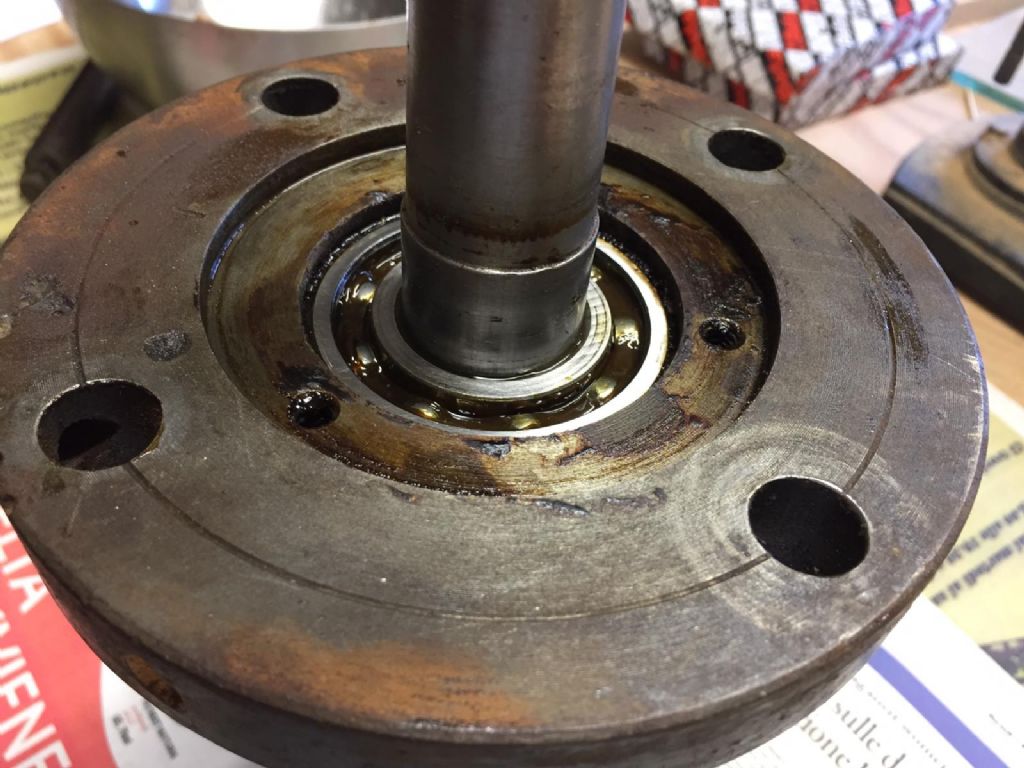
I need to get the bearings out and I guess I need to remove the shaft first. I assume I need a press for that, but is there any way of knowing which end to press out? To keep the pulley aligned with the motor pulley, and the bottom wheel aligned with the top bandsaw wheel the shaft will need to be put back in the same position. Is it possible that it is somehow seated on something inside the casting? Not sure where to start.
|
| Steviegtr | 08/03/2021 14:29:20 |
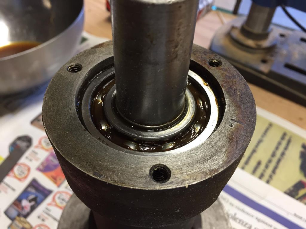
 2668 forum posts 352 photos | 1st off i would try to remove the silver cover in pic 1. This may reveal something. Otherwise it will need to be be pressed from one side. Also look for a circlip in the route of the bearing in pic 3. Steve. |
| Howard Lewis | 08/03/2021 14:45:27 |
| 7227 forum posts 21 photos | The three grubscrews are either dutch keys, or clamp screws for a taperlock type fitting. They should be completely removed. It may then be possible to remove the shaft from that end. The bearing at the other end could then be removed using a suitably sized dolly, working from the flange end. Then turn end for end and drive out the other bearing, if it did come out with the shaft. Howard |
| Nicholas Farr | 08/03/2021 15:12:39 |
 3988 forum posts 1799 photos | Hi pgrbff, I would think the bearing under the cover plate will be the one that sets the position of the shaft and it will probably have to be pressed out from the end that you can see the other bearing. That bearing is likely to stay in the housing and can be removed once the shaft is out, I doubt that is a very tight fit inside the housing, as I imagine it will have a little end float for expansion and contraction during use and temperature changes. Regards Nick. Edited By Nicholas Farr on 08/03/2021 15:16:16 |
| pgrbff | 08/03/2021 17:16:58 |
| 261 forum posts 31 photos | I'm hoping there will be a circlip under the aluminium plate but all efforts to pry it off have failed so far. The holes are through holes and not threaded so I can't pull it off. There were 3 slotted machine screws holding it on. I'm trying to avoid drilling it to get better purchase. |
| Brian Wood | 08/03/2021 17:23:23 |
| 2742 forum posts 39 photos | Is it a screwed in cover and the three holes are there to fit a pin spanner? Regards Brian |
| Swarf Maker | 08/03/2021 17:30:01 |
| 132 forum posts 7 photos | It has to be simple. The disc with three holes is likely there to retain the bearing in the housing. Tap the far end of the shaft with a copper mallet and the shaft will likely exit, bringing the bearing and that ring with it. once out and clear of the housing the other bearing can be removed from the opposite end by judicious use of a drift through the housing. Do the first exploratory taps and see what starts to move to confirm. |
| Tom Sheppard | 08/03/2021 18:31:19 |
| 47 forum posts | The narrow end of the assembly has a circlip which is to prevent the shaft being pushed through the wide end. Remove it and the shaft goes thataway. Detach the cover at the wide end to ensure there is no increased diameter behind it. |
| Nicholas Farr | 08/03/2021 18:42:01 |
3988 forum posts 1799 photos | Hi pgrbff, you could try putting a couple of snug fitting pins into two of those holes in that plate, but make sure they are no deeper in than the thickness of the plate and then get a pry bar or just a suitable length piece of bar and use it as a lever between the two pins and see if it will turn, squirt a bit of penetrating oil round the joint to help free it up and you may be able to wiggle it out. Regards Nick. |
| not done it yet | 08/03/2021 19:33:08 |
| 7517 forum posts 20 photos | First question might be why does it need to come apart? One end of that shaft looks to be of larger diameter than the other (close to the bearing) in the pic. Is that so? If it is, it will be clear that it is retaning that bearing against a shoulder on the shaft and will not pass through the bearing from that end. |
| David Caunt | 08/03/2021 20:42:42 |
 110 forum posts 40 photos |
If the arrow is pointing at a circlip then that would be the way forward. |
| Nigel Graham 2 | 08/03/2021 22:21:48 |
| 3293 forum posts 112 photos | It does look like a circlip, and one nicely accessible to circlip pliers, at that! If you have to remove the pulley too, the shiny bit looks like a Taper-loc hub to me - but if so it will have a tell-tale slot that allows it to close onto the shaft, may have a key-way, and normally has two grub-screws for grip. The third hole is for removing it, using a screw. I forget off-hand the methods for removing and refitting those hubs, but it is very simple, using only the appropriate Allen key. I would guess that the shaft has at least one shoulder on it so the components can be fitted in their proper places.
|
| pgrbff | 10/03/2021 08:59:45 |
| 261 forum posts 31 photos | Posted by Brian Wood on 08/03/2021 17:23:23:
Is it a screwed in cover and the three holes are there to fit a pin spanner? Regards Brian No pin spanner. Just three holes that had machine screws in them to hold the plate on.
Edited By pgrbff on 10/03/2021 09:00:05 |
| pgrbff | 10/03/2021 09:03:50 |
| 261 forum posts 31 photos | Posted by David Caunt on 08/03/2021 20:42:42:
If the arrow is pointing at a circlip then that would be the way forward. No circlips either end. |
| pgrbff | 10/03/2021 09:08:02 |
| 261 forum posts 31 photos | Posted by Nigel Graham 2 on 08/03/2021 22:21:48:
It does look like a circlip, and one nicely accessible to circlip pliers, at that! If you have to remove the pulley too, the shiny bit looks like a Taper-loc hub to me - but if so it will have a tell-tale slot that allows it to close onto the shaft, may have a key-way, and normally has two grub-screws for grip. The third hole is for removing it, using a screw. I forget off-hand the methods for removing and refitting those hubs, but it is very simple, using only the appropriate Allen key. I would guess that the shaft has at least one shoulder on it so the components can be fitted in their proper places.
The shaft under the pulley is very slightly tapered 1mm over 42mm, but no key-way or slot. Pulley is a simple press fit, with no grub screws or other means to stop it turning other than the taper. |
| pgrbff | 10/03/2021 09:13:28 |
| 261 forum posts 31 photos |
I guess I'm going to have to find someone with a hydraulic press. There are no circlips. I'm not sure how I'm supposed to know which end to push it out from but maybe it doesn't matter. I have measured as best I can how far the shafts protrude from each end. |
| Hopper | 10/03/2021 09:43:32 |
 7881 forum posts 397 photos | If you push it the wrong way with 20 tons of hydraulic pressure you could burst the whole thing asunder. Instead, support the housing on two block of wood and firmly hit the end of the shaft with a heavy hammer and brass drift - or piece of wood. Use suitable restraint of course and check frequently if the large lower bearing is moving out of the housing, or if the shaft is moving in the upper bearing. Hit it on the small end where the smaller bearing is. Usually that type of set up will go in from the large end and come back out the large end. The small bearing will probably stay where it is, up against a shoulder, and the larger bearing should come out with the spindle. Then you can knock the smaller bearing out. Heating the body with a torch will reduce the force needed to move the bearings.
Edited By Hopper on 10/03/2021 10:00:13 |
| Nicholas Farr | 10/03/2021 10:26:51 |
3988 forum posts 1799 photos | Hi pgrbff, more or less as Hopper says, it is likely that the inner race of both bearings will be against a shoulder on the shaft and one bearing will be locked in the housing by the cover plate and the other end will have room the float each way, so when pressing you may see the bearing on the end you are pressing, move slightly further into the housing until the outer race reaches a shoulder inside the housing. It shouldn't take an awful lot of pressure to press it out though, so if you decide to press it one way and does not seem to move, then stop and try it the other way. Personally, I would try pressing the short end of the shaft. Regards Nick. |
| Redsetter | 10/03/2021 10:34:51 |
| 239 forum posts 1 photos | Pgrbff - Why the overwhelming urge to take the bearings out anyway? Are they obviously worn or noisy? If not, they are probably best left alone. Remember you will have to put them back in correctly and without without damaging them. Assuming you want the machine to work again, of course. |
| pgrbff | 10/03/2021 10:57:01 |
| 261 forum posts 31 photos | No overwhelming urge. I haven't run the saw so to be honest I don't know how they are. The bearings in the top wheel were quite rough when I took them out. As I have the saw apart I think it prudent to swap out the bearings rather than put it back together and then discover they need changing. I have very poor/difficult access to my workshop over grass. The saw weighed around 250 kg so I dismantled it to get it home. I was going to replace the bearings with open ones like original but several people on here suggested I replace them with sealed. |


Please login to post a reply.
Magazine Locator
Want the latest issue of Model Engineer or Model Engineers' Workshop? Use our magazine locator links to find your nearest stockist!
Sign up to our Newsletter
Sign up to our newsletter and get a free digital issue.
You can unsubscribe at anytime. View our privacy policy at www.mortons.co.uk/privacy
Latest Forum Posts
- *Oct 2023: FORUM MIGRATION TIMELINE*
05/10/2023 07:57:11 - Making ER11 collet chuck
05/10/2023 07:56:24 - What did you do today? 2023
05/10/2023 07:25:01 - Orrery
05/10/2023 06:00:41 - Wera hand-tools
05/10/2023 05:47:07 - New member
05/10/2023 04:40:11 - Problems with external pot on at1 vfd
05/10/2023 00:06:32 - Drain plug
04/10/2023 23:36:17 - digi phase converter for 10 machines.....
04/10/2023 23:13:48 - Winter Storage Of Locomotives
04/10/2023 21:02:11 - More Latest Posts...
- View All Topics
Support Our Partners


Shopping Partners
Subscription Offer

Latest "For Sale" Ads
- Reeves** - Rebuilt Royal Scot by Martin Evans
by John Broughton
£300.00 - BRITANNIA 5" GAUGE James Perrier
by Jon Seabright 1
£2,500.00 - Drill Grinder - for restoration
by Nigel Graham 2
£0.00 - WARCO WM18 MILLING MACHINE
by Alex Chudley
£1,200.00 - MYFORD SUPER 7 LATHE
by Alex Chudley
£2,000.00 - More "For Sale" Ads...
Latest "Wanted" Ads
- D1-3 backplate
by Michael Horley
Price Not Specified - fixed steady for a Colchester bantam mark1 800
by George Jervis
Price Not Specified - lbsc pansy
by JACK SIDEBOTHAM
Price Not Specified - Pratt Burnerd multifit chuck key.
by Tim Riome
Price Not Specified - BANDSAW BLADE WELDER
by HUGH
Price Not Specified - More "Wanted" Ads...
Get In Touch!
Do you want to contact the Model Engineer and Model Engineers' Workshop team?
You can contact us by phone, mail or email about the magazines including becoming a contributor, submitting reader's letters or making queries about articles. You can also get in touch about this website, advertising or other general issues.
Click THIS LINK for full contact details.
For subscription issues please see THIS LINK.
Digital Back Issues


Donate

 Register
 Log-in
Model Engineer Magazine
- Percival Marshall
- M.E. History
- LittleLEC
- M.E. Clock

ME Workshop
- An Adcock
- & Shipley
- Horizontal
- Mill

Subscribe Now
- Great savings
- Delivered to your door

Pre-order your copy!
- Delivered to your doorstep!
- Free UK delivery!
All Forum Topics > Beginners questions > How do I get the bearings out of this?