Forum sponsored by:

cross slide dept stop
| larry phelan 1 | 16/05/2020 18:36:00 |
| 1346 forum posts 15 photos | Good evening all,, I,m wondering if anyone can enlighten me as to where I am going wrong. I have made a simple stop to limit the travel of the cross slide on my lathe in order to get consistent diameters each time. It consists of a screw, fixed to the cross slide which meets a stop fixed to the back of the carriage, nothing fancy. In order to make it more useful, I fitted it with a rotating disc in order to fit three such stops. It works fine, as a stop, but the results are far from consistent, anything from 2thou to 6 thou on all three diam,s. I have tried locking the cross slide but it made little difference. Any idea,s ? I have taken pictures which I will try to post All help welcome. |
| AdrianR | 16/05/2020 18:47:04 |
| 613 forum posts 39 photos | Is that variation when you are cutting or with a DTI? If you put a DTI on the tool post and set it against your work, does it show the same variation each time you hit the stop? Could it be you are varying the force you are using against the stop? The stop could be flexing. The slide could be twisting.
Adrian |
| Andrew Johnston | 16/05/2020 18:47:52 |
 7061 forum posts 719 photos | The obvious assumption is that the stop is not rigid enough, but pictures will help. For comparison I'd expect to hit a diameter to a thou or less just using the same dial reading on my cross slide. Andrew |
| larry phelan 1 | 16/05/2020 19:05:16 |
| 1346 forum posts 15 photos | First off, I did not try a DTI ,the variation is when I,m cutting, even with a very fine feed. I tried to be gentle when bringing the unit to the stop, which is made from a piece of 40x10 which happened to be to hand. Not much chance of it flexing. I will try the DTI in the toolpost Andrew, I was hoping to avoid having to check the dial each time since I hope to use this thing when making a batch of small units. I did take pictures, but I,m still trying to work out how to get them from A to B, if you know what I mean For now, it,s back to the drawing board. |
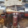
| larry phelan 1 | 16/05/2020 19:34:56 |
| 1346 forum posts 15 photos | Back again, I did manage to get those pictures into my album [don't even ask how ]. I hope you may be able to make it out, it is simply a piece of 10mm bar which carries a disc fitted with three screws which can be brought to bear against a piece of 10mm flat.. As I said, even with the cross slide locked, when two pieces are machined at the same setting, there is a variation and a lot more than 1 thou. |
| Tony Pratt 1 | 16/05/2020 20:10:11 |
| 2319 forum posts 13 photos | Something is flexing possible the angle bracket, it's suprising how much force you can apply with a screw. Tony |
| bricky | 16/05/2020 20:16:48 |
| 627 forum posts 72 photos | Larry, I think the bracket may be flexing and that a block would give a more consistant result. Frank |
| old mart | 16/05/2020 20:39:54 |
| 4655 forum posts 304 photos | I have never heard of a cross slide stop being used on a lathe. It would have to be extremely rigid to have much of a chance. I recon that the reason a stop is not used in that application normally is because it is so easy to zero the dial when taking the last cut on the first workpiece. |
| old mart | 16/05/2020 20:39:55 |
| 4655 forum posts 304 photos | I have never heard of a cross slide stop being used on a lathe. It would have to be extremely rigid to have much of a chance. I recon that the reason a stop is not used in that application normally is because it is so easy to zero the dial when taking the last cut on the first workpiece. |
| Andrew Johnston | 16/05/2020 20:42:00 |
7061 forum posts 719 photos | I'd agree that the angle bracket is flexing; you only need it to deflect half of the diameter error. As to the error with the cross slide locked, that'll probably be down to something else. May tool or work deflection? Or the lock isn't that effective for the loads being applied? Andrew |
| Clive Brown 1 | 16/05/2020 21:39:33 |
| 1050 forum posts 56 photos | GHT published a cross-slide stop for the Myford. Here's my take on his design for a Boxford. It is really intended for screw-cutting when the cut is put on with the top-slide. It can be useful, saving mistakes, and repeats position quite well. As I recall, the tapped BSW hole was already in the cross-slide from new.
|
| Chris V | 16/05/2020 21:57:40 |
 313 forum posts 42 photos | Hi Clive, what book is the GHT design in please? Chris. |
| Bazyle | 16/05/2020 21:58:37 |
 6956 forum posts 229 photos | Several of the bigger industrial lathes have cross slide stops as standard, sometimes a T-slot along the edge of the slide. There was a nice design for the Myford in ME about 30 years ago that incorporated a click detent on the adjusting knob so you could get close then make final increments on cut by feel more than peering at the dial. I have always remembered that feature and wanted to do something for a Boxford but the slide moves in a different way. I wonder if Larry's problem is partly that the screw that allows the holder to turn to select 3 options implies some looseness that allows the whole ring to tilt. |
| Pete Rimmer | 16/05/2020 23:44:35 |
| 1486 forum posts 105 photos | Larry if you want to test if the stop or bracket is flexing simply put a dial gauge on the opposite side and run the cross slide up to it. The gauge will show any movement, which will be doubled on diameter as pointed out by Andrew Johnston |
| Hopper | 16/05/2020 23:48:10 |
 7881 forum posts 397 photos | Hard to tell from the pics with nothing to give scale but the whole thing looks a bit small and flexible. Needs to be something of similar heft as the cross slide itself, more like the one in the pic Clive posted above. Your 3 bolts that form the actual stops would need to be at least 5/16" diameter I should think. I would make it 3/8 for good measure. And the body a good half inch thick or more. Basically, needs to be immovable as your cross slide screw exerts more force than you might realise. |
| Nigel Graham 2 | 17/05/2020 00:55:07 |
| 3293 forum posts 112 photos | Chris V - With respect the photo is almost the design. You'd have to measure the lathe to ascertain dimensions. The Allen screw goes through a clearance-hole in the clamp-block, to a tapped hole that happened already to be in the cross-slide. (I wonder what that hole was intended for?). The stop action is thus by the underside of the cap-screw contacting the block. Note the flexing-point for the clamp is the small hole near the top right edge; the cap-screw that actuates the clamp should be sufficiently far down for proper clamping action without an unduly weak wall between the thread and the block's underside. The clearance hole is just a tad generous, but not overly so if the Vees meet as they should. ' Larry - I would agree that stop as made is a bit too slender. The principle is very good and I am only surprised such stops are not more common. It does though, need to be very rigid and positive. The bracket could be made far more rigid by welding or brazing a triangular gusset across both ends to make a Vee-box form, rather as many angle-plates are cast. Or replaced by similar machined from a cube. It's a bit hard to see details but the central shaft and whatever it fits in, look a little thin. ' I have the essence of a 6-station saddle (rather than cross-slide) stop from an old industrial lathe, and the rotary part is a cylindrical sleeve a close sliding fit on a rigid stator. As far as I can tell, its central Allen screw pulled the back of the stator onto a spot-facing on the apron. The trick is that the stop-screw carrier has as much bearing surface as possible for the rotary part of a unit probably little larger than yours, and it revolves on a part held in the most rigid way it can be. The stop-screws thus thread down inside the wall of the sleeve. What you might consider is modifying / making new the bracket to be much more rigid. Then, if that does not entirely solve the problem, make the stop-carrier as above: a closely-fitting sleeve pulled back by a hefty screw to a facing on the bracket.. My industrial version had the extra luxury of a detent arrangement and operating-handle, as on a rotary tool-post, but that's for another day! The length-stops themselves on my example - which I have not used - are square-head screws, 5/16-in BSF I think, with lock-nuts, that met a domed fine-adjustment screw in the end of a bar dimpled for coarse adjustment within its mounting-block. My Myford 7 certainly does not, and the Harrison L5 appears not, to provide for mounting this device. |
| Clive Brown 1 | 17/05/2020 09:06:19 |
| 1050 forum posts 56 photos | Posted by Chris V on 16/05/2020 21:57:40:
Hi Clive, what book is the GHT design in please? Chris. Hi Chris, just a quick reply, Nigel Graham 2 has explained the device very clearly. The design was in ME back in the 'eighties.Don't know if it ever made it's way into a book. GHT later designed a retracting tool-holder which might be seen as a Rolls-Royce method of doing a similar job. I didn't make one of those. |
| Chris V | 17/05/2020 09:42:11 |
313 forum posts 42 photos | Thank you Nigel Graham 2 & Clive, yes that's clearer now in my mind! Chris. |
| ega | 17/05/2020 10:10:56 |
| 2805 forum posts 219 photos | There have been various designs for lath cross slide stops eg Sparey's arrangement which occupies the space often taken by a DRO and Tubal Cain's rather different device to aid screwcutting. Incidentally, to be useful a cut-off slide will normally incorporate stops. Here is my shop-made version of the Boxford stop as fitted to my Willson slant bed:
And my own design for the Myford:
Both were intended as aids to screwcutting and have been effective; so far, however, neither has proved totally repeatable in use. |
| larry phelan 1 | 17/05/2020 10:28:41 |
| 1346 forum posts 15 photos | I don't know where to start when it comes to thanking you all for your input ! I am simply amazed that so many took the trouble over something so small. Thinking the whole thing over last night,I came to the same conclusion ,that the whole thing was too light and flimsy. I think that the angle piece is far too light, a solid block would be a better idea there and the screws need beefing up. How was I stupid enough to believe it would work ? [Don't dare answer that !! ] It is now a case of "Back to the drawing board ", but much wiser this time around. I will build another one because it can be useful when making large numbers of items and if it works out better this time around, I will post some pictures of the Mark Two model. Again, my thanks to everyone who replied. As they say, "Every little helps " Take care everyone |


Please login to post a reply.
Magazine Locator
Want the latest issue of Model Engineer or Model Engineers' Workshop? Use our magazine locator links to find your nearest stockist!
Sign up to our Newsletter
Sign up to our newsletter and get a free digital issue.
You can unsubscribe at anytime. View our privacy policy at www.mortons.co.uk/privacy
Latest Forum Posts
- *Oct 2023: FORUM MIGRATION TIMELINE*
05/10/2023 07:57:11 - Making ER11 collet chuck
05/10/2023 07:56:24 - What did you do today? 2023
05/10/2023 07:25:01 - Orrery
05/10/2023 06:00:41 - Wera hand-tools
05/10/2023 05:47:07 - New member
05/10/2023 04:40:11 - Problems with external pot on at1 vfd
05/10/2023 00:06:32 - Drain plug
04/10/2023 23:36:17 - digi phase converter for 10 machines.....
04/10/2023 23:13:48 - Winter Storage Of Locomotives
04/10/2023 21:02:11 - More Latest Posts...
- View All Topics
Support Our Partners


Shopping Partners
Subscription Offer

Latest "For Sale" Ads
- Reeves** - Rebuilt Royal Scot by Martin Evans
by John Broughton
£300.00 - BRITANNIA 5" GAUGE James Perrier
by Jon Seabright 1
£2,500.00 - Drill Grinder - for restoration
by Nigel Graham 2
£0.00 - WARCO WM18 MILLING MACHINE
by Alex Chudley
£1,200.00 - MYFORD SUPER 7 LATHE
by Alex Chudley
£2,000.00 - More "For Sale" Ads...
Latest "Wanted" Ads
- D1-3 backplate
by Michael Horley
Price Not Specified - fixed steady for a Colchester bantam mark1 800
by George Jervis
Price Not Specified - lbsc pansy
by JACK SIDEBOTHAM
Price Not Specified - Pratt Burnerd multifit chuck key.
by Tim Riome
Price Not Specified - BANDSAW BLADE WELDER
by HUGH
Price Not Specified - More "Wanted" Ads...
Get In Touch!
Do you want to contact the Model Engineer and Model Engineers' Workshop team?
You can contact us by phone, mail or email about the magazines including becoming a contributor, submitting reader's letters or making queries about articles. You can also get in touch about this website, advertising or other general issues.
Click THIS LINK for full contact details.
For subscription issues please see THIS LINK.
Digital Back Issues


Donate

 Register
 Log-in
Model Engineer Magazine
- Percival Marshall
- M.E. History
- LittleLEC
- M.E. Clock

ME Workshop
- An Adcock
- & Shipley
- Horizontal
- Mill

Subscribe Now
- Great savings
- Delivered to your door

Pre-order your copy!
- Delivered to your doorstep!
- Free UK delivery!
All Forum Topics > Help and Assistance! (Offered or Wanted) > cross slide dept stop