Forum sponsored by:

Measuring wear on a surface grinder
| Dave S | 23/04/2020 22:00:47 |
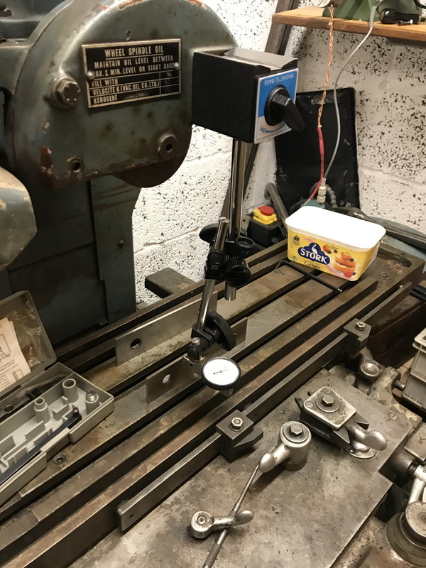
| 433 forum posts 95 photos | I’ve just got my J&S 540 full of oil and moving. Its been run hard and put up wet in a previous life - it came from a mould makers IIRC. I don’t have the spindle running yet, but though I might be able to take some indicative measurements to see if it’s worn out or likely to be ok. I took the most parallel thing I have ( an import parallel from the mill) and stood it on a section of the table which is shiny and appears to be the original surface- it was I think under the mag chuck. then I mounted my best indicator- mitutoyo tenths one that only comes out on special occasions - on the wheel guard with a mag stand.
Is this a valid method to get a measurement for wear on the ways? Dave
|
| Hopper | 24/04/2020 03:00:35 |
 7881 forum posts 397 photos | Some, but a bit limited I would say. You should try to get hold of a copy of Connelly's book "Machine Tool Reconditioning" for a thorough run through on measuring machine tool run out etc. I'd question the use of a tenths dial indicator away out on the end of an extended adjustable mag base stand like that, with the flexible fine adjustment in the middle of one arm too. And then it's mounted on the flimsy wheel guard (by machine tool standards) which could introduce unwanted movement of a thou or three. Mag base might be better mounted on the column with dial gauge as close to tthe base as possible to minimise springy overhang. Parallel stood on edge unsecured like that could be likely to move enough to influence reading too. Then there is the question of what you are measuring. The ways the table runs on could be well low at one end and that dial could still read zero as it passes by the gauge finger. It will measure if the surface of the table is not parallel to the sliding way surface on the bottom of the table at that particular point, maybe, if it is not riding on other points further along the ways. The best way to really accurately measure way wear is to strip the machine and measure the ways with micrometers, dial gauges mounted on suitable "sleds" or sliding bases and/or maybe straight edges and feeler gauges. Probably a more practical way would be to set the gib strips by feel. Set them so they are shake free in the middle of the table's run then see if they get tight when the table is slide by hand to one end or the other. Or go the other way and set gibs shake free at one end and then see if there is slack in the more worn middle section. Then you are probably better off to set a job up in the machine and take some trial cuts and measure the resulting thicknesses. A couple of test strips about the size of those parallels you have laid down flat would probably suffice. Looks like a right handy piece of machinery for the workshop. Keep us posted on how it goes. Edited By Hopper on 24/04/2020 03:01:30 |
| David George 1 | 24/04/2020 07:27:38 |
 2110 forum posts 565 photos | Hi Dave these are fairly bomb proof as far as to the bed ways are concerned you will grind the top of the bed and then the top of the magnetic chuck so that it can't but help to be parallel. The things that cause wear and trouble are the hydraulic pump which can lose pressure if it is worn, the chainwheel and chain between the motor and pump, and the return ways for the hydraulic oil which become blocked by dirt and debris. There are a few other things like the piston seals on the hydraulic cylinder but they are readily available. There is a company called Andmar which is useful https://www.andmar.co.uk/ worth a look . I would look in the hydraulic tank as the oil can be quite grotty after a long time in a toolroom and clean it out before refilling with oil also checking for holes in the tank as they are prone to rusting as any coolant sinks to the bottom of the tank and after a while may cause leaks. Good look give it a good clean and it will last forever. David Edited By David George 1 on 24/04/2020 07:28:12 |
| not done it yet | 24/04/2020 07:58:53 |
| 7517 forum posts 20 photos | And then there are the spindle bearings.... Measuring for tenths over 8 inches with a cheap parallel stood on a scruffy table adds to Hopper’s points of getting any serious measurements of any worth. As he says a job of good length is likely to tell you more - after at least giving the table a good cleaning and stoning. It may not even be flat and level, so it may need grinding before any sensible conclusions can be drawn. How accurate do you want your finished jobs to be? Even beyond industrial use it may be good enough for the home hobbyist - ie better than a milled finish. Spindle bearings are likely the biggest headache if the machine has not been run ‘dry’. |
| Dusty | 24/04/2020 09:03:36 |
| 498 forum posts 9 photos | Dave I would caution against attempting to grind the bed of the machine. The grinder was not designed to grind over this length, you will almost certainly get rocking of the bed at the ends if you try it. I would just make sure the bed is as flat as you can get it by using a large stone, make sure the bottom of the Mag chuck is clean and free from burrs. Put the mag chuck on the machine, making sure it is parallel to the machine. This is so you can use the setting strip at the back. Grind the surface of the Mag chuck, make sure you start from the highest point of the chuck, you don't want to start grinding with a thou and half way across you have a 5 thou cut. Best of luck. Dusty |
| Chris Evans 6 | 24/04/2020 09:14:07 |
 2156 forum posts | I have used a lot of 540 machines, even with minimum care they are a good 30 year machine. The only one I can remember with a wear problem was on the cross slide which showed up on full width. I would put a systems cleaner in the hydraulic oil and run daily for a few hours after manually cleaning any blocked oilways. Change the oil then fit the mag chuck, grind the chuck when the machine is warm (leave it running with table moving for three hours) I doubt you will detect much if any wear in use for normal work. |
| Peter Bell | 24/04/2020 09:23:51 |
| 399 forum posts 167 photos | I got a wartime Norton grinder (18" x 6" I found the spindle had excessing play using a DTI which I corrected. After that it was a case of measuring a ground piece and seeing the surface finish--whole new world of leaning for me! Certainly looks decent, sure you will find it a very useful tool Peter |
| Baz | 24/04/2020 09:24:21 |
| 1033 forum posts 2 photos | Totally agree with Dusty, take a skim over the mag chuck and that will be as good as you will ever get regarding accuracy, you don’t say what accuracy you expect or what you intend grinding, are you looking for just a good finish, within a couple of tenths or are you looking to split the atom on it👍. When you grind the top of the mag chuck I was always told to do it with the magnets on, others say off, I wonder which way other members on this forum were taught, and reasons why. |
| not done it yet | 24/04/2020 09:30:58 |
| 7517 forum posts 20 photos | Posted by Dusty on 24/04/2020 09:03:36:
Dave I would caution against attempting to grind the bed of the machine. The grinder was not designed to grind over this length, you will almost certainly get rocking of the bed at the ends if you try it. I would just make sure the bed is as flat as you can get it by using a large stone, make sure the bottom of the Mag chuck is clean and free from burrs. Put the mag chuck on the machine, making sure it is parallel to the machine. This is so you can use the setting strip at the back. Grind the surface of the Mag chuck, make sure you start from the highest point of the chuck, you don't want to start grinding with a thou and half way across you have a 5 thou cut. Best of luck. Dusty Probably better to grind the magnet base first, so that the skim from the top surface is the minimum possible. |
| SillyOldDuffer | 24/04/2020 10:02:04 |
| 10668 forum posts 2415 photos | Posted by Dave S on 23/04/2020 22:00:47: ... I don’t have the spindle running yet, but though I might be able to take some indicative measurements to see if it’s worn out or likely to be ok. ...
Is this a valid method to get a measurement for wear on the ways? Dave
Sort of, but may I take the opportunity to suggest measuring isn't a good way to start diagnosing unknown machine problems? Trouble is precision measuring is easy to get wrong and liable to lead one deep into a contradictory maze. The pitfalls have been known to mislead experts. For example, using a tenths indicator on the end of a long boom is asking for trouble. It mixes measurement errors up randomly with any problem the machine might, or might not have. Unsafe to draw any conclusions from the results. As first step I think it's much safer to test the machine by using it to cut metal. If it it performs properly, looking for trouble with a DTI is a waste of time! Conversely, If a machine doesn't cut properly, what's wrong with the cut should provide useful clues. Now is the time to get out the specification, DTI, and straight-edges etc. Precision measurements are invaluable for pinning down exactly what a known problem is and what needs to be done to fix it, precision is less effective, even dangerous, as an early indicator. By analogy, most would test a prospective second-hand car purchase by taking it for a run round the block. At this stage failure to start, warning lights, weak brakes, slipping clutch, notchy gearbox, shrieking water-pump, noisy exhaust and oil in the road are all much more revealing than whipping the head off and carefully measuring the cylinder diameters for signs of wear! Dave
|
| Andrew Johnston | 24/04/2020 10:19:40 |
 7061 forum posts 719 photos | Posted by Dave S on 23/04/2020 22:00:47:
Is this a valid method to get a measurement for wear on the ways? The short answer is that it isn't going to tell you anything particularly useful. At best It might give an indication of the quality of the parallel, although given the narrowness of the parallel and overhang of the indicator I doubt even that. I'd agree that the condition of the ways is likely to be the least of your problems. The ways don't wear like those on a lathe for instance for several reasons: The cutting forces are very low - on both my surface and cylindrical grinders the tables just rest on the ways, there's nothing holding them down The ways have a large bearing area compared to the forces They should be continuously lubricated The ways are well protected from grinding dust The ways are in contact over the full area most of the time, unlike the saddle on a lathe bed Ways can be fixed but it's an involved process. IIRC there was a thread a while back on 'practicalmachinist' about scraping the ways on a cylindrical grinder. Pretty darn involved. I'd agree with some of the points above. It's normal to grind the top of mag chuck in situ, so that removes many of the issues. On the older grinders problems are much more likely to be due to spindle bearings, especially if they're plain bearings. While the finish I get on my 1940s surface grinder isn't the best (pretty sure the spindle bearings are shot) it still grinds flat and parallel to better than I can measure with micrometers. Same is true of my 1960s cylindrical grinder; with some tweaking I can get a tenth or better on diameter over 10". Andrew
|
| Dave S | 24/04/2020 13:13:47 |
| 433 forum posts 95 photos | Thanks all. The oil for the spindle is on order, so I cant actually grind anything yet. I thought last night as I was running the movement system anyway to get the oil flowing properly I would try some 'look see' sort of measurement. After all the machine is from 1960, so its knocking on a bit. I'm not looking to diagnose anything yet, I haven't actually run the machine, despite owning it for 12 odd years. I believe that it was removed from the tool rom after the main motor failed to start, not because it was worn out. That issue turned out to be purely dirty switchgear - I did do that much when I got it.... I didn't think it was a very good way to measure, hence asking. My thinking was that rather than cutting the block to size as it passed the 'wheel' if there was a gross deviation then the indicator would show it - something like 'banana' ways for instance. As it happens the indicator shows well under a tenth deviation. I took a video, but not sure how I could post it? The smooth movement of the hydraulics means the thin parallel stayed stood up and didn't move at all over multiple passes. Fingers crossed for the spindle when the oil gets here - its the plain bearing version so I don't know how I'd sort that if it needed it. Dave |
| Chris Evans 6 | 24/04/2020 14:46:25 |
2156 forum posts | There are two types of drive belt for the spindle. The oil filled heads use a belt with a sort of felt backing. It is critical to use the correct belt for the machine. As mentioned above Andmar in Leicestershire carry parts. |
| Pete Rimmer | 24/04/2020 19:01:19 |
| 1486 forum posts 105 photos | It's very possible to have the machine so worn that it produces 'bent' parts and grinding the chuck will not fix that nor will the popular test of putting blocks on the corners of the chuck and grinding them to compare the thicknesses. I had one of these and the cross axis ways were so worn that anything I ground was convex in the short axis. i did set about re-scraping it but after a lot of work lost heart and got rid of it, mostly because I didn't have a straight edge to fit the cross table ways (you can't fit a regular straight edge in there) and because the wear so so bad that the cross slide screw and nut were trying to carry the weight of the cross slide and table. You can use your test to check for 'banana ways' but orientate the straight edge across the chuck and check that axis. If the ways are straight it will either indicated evenly along the length or have a gradual rise or fall on the dial. If they are as badly worn as mine the indicator will fall then rise showing a low reading in the middle.
Edited By Pete Rimmer on 24/04/2020 19:08:17 |
| old mart | 24/04/2020 20:53:23 |
| 4655 forum posts 304 photos | Have you tried it with the parallel pointing the other way? |
| Dusty | 25/04/2020 10:27:34 |
| 498 forum posts 9 photos | My only bit of advice is don't try to fix problems you don't have. Get the machine together grind the chuck, then grind a piece of steel making sure it at least 15mm thick. Thinner stuff can be pulled down onto the chuck and distorted giving false readings. If you then find problems they can be fixed as you will know what they are. |
| Pete Rimmer | 25/04/2020 11:55:22 |
| 1486 forum posts 105 photos | If the cross table ways are worn and you grind the chuck you'll be grinding the chuck convex. If someone hasn't already done it. |
| Dave S | 25/04/2020 12:54:08 |
| 433 forum posts 95 photos | Crosswise on the 6” parallel is less clear. Might be a ramp of about 6-8 tenths, but sometimes it appears to be a dip of 3-4 tenths, but not consistently and not at the same point in the travel. On a 123 block it is less, but as well as being a larger thermal mass it’s shorter... Its certain that it isn’t very bad, and the proof will be in grinding something. I do intend to use first and see, rebuilding is not a project I want. Dave |
| Pete Rimmer | 25/04/2020 15:01:56 |
| 1486 forum posts 105 photos | Posted by Dave S on 25/04/2020 12:54:08:
Crosswise on the 6” parallel is less clear. Might be a ramp of about 6-8 tenths, but sometimes it appears to be a dip of 3-4 tenths, but not consistently and not at the same point in the travel. Dave It's a sign of wear in the slide. I'll try to do a sketch to explain it. EDIT: I don't have to - I found an old pic of the wear on mine.
As you can see the ways wear low at both ends and this causes the cross table to travel in an arc instead of a straight line. When you put the parallel on the chuck it IS straight, so making it travel in an arc with the table will give a high reading at both ends. The reason you're getting different reading in both directions is probably because the table is rocking ever so slightly away from the direction of travel. As you can see - mine was badly worn, much more than your indicated figures. Edited By Pete Rimmer on 25/04/2020 15:12:20 |
| Howard Lewis | 25/04/2020 15:45:48 |
| 7227 forum posts 21 photos | Since you are measuring with a tenths of a thou indicator, you are looking to be able to detect, accurately, differences of less mthan a tenth. You cannot afford to have flexibility of anything near a tenth, so the DTI mounting must be as rigid as possible. If there is any detectable flexibility, it will be difficult to tell if the deflection is ,wear (that you want to measure ) or flexibility which you can't; and don't want! You can't measure accurately with a graduated bungee cord! Howard. |
 at the right price which by appearance I expected to be compleley worn out but it turned out the ways are lubricated by the hydraulic pump and were perfect.
Please login to post a reply.
Magazine Locator
Want the latest issue of Model Engineer or Model Engineers' Workshop? Use our magazine locator links to find your nearest stockist!
Sign up to our Newsletter
Sign up to our newsletter and get a free digital issue.
You can unsubscribe at anytime. View our privacy policy at www.mortons.co.uk/privacy
Latest Forum Posts
- hemingway ball turner
04/07/2025 14:40:26 - *Oct 2023: FORUM MIGRATION TIMELINE*
05/10/2023 07:57:11 - Making ER11 collet chuck
05/10/2023 07:56:24 - What did you do today? 2023
05/10/2023 07:25:01 - Orrery
05/10/2023 06:00:41 - Wera hand-tools
05/10/2023 05:47:07 - New member
05/10/2023 04:40:11 - Problems with external pot on at1 vfd
05/10/2023 00:06:32 - Drain plug
04/10/2023 23:36:17 - digi phase converter for 10 machines.....
04/10/2023 23:13:48 - More Latest Posts...
- View All Topics
Support Our Partners


Shopping Partners
Subscription Offer

Latest "For Sale" Ads
- Reeves** - Rebuilt Royal Scot by Martin Evans
by John Broughton
£300.00 - BRITANNIA 5" GAUGE James Perrier
by Jon Seabright 1
£2,500.00 - Drill Grinder - for restoration
by Nigel Graham 2
£0.00 - WARCO WM18 MILLING MACHINE
by Alex Chudley
£1,200.00 - MYFORD SUPER 7 LATHE
by Alex Chudley
£2,000.00 - More "For Sale" Ads...
Latest "Wanted" Ads
- D1-3 backplate
by Michael Horley
Price Not Specified - fixed steady for a Colchester bantam mark1 800
by George Jervis
Price Not Specified - lbsc pansy
by JACK SIDEBOTHAM
Price Not Specified - Pratt Burnerd multifit chuck key.
by Tim Riome
Price Not Specified - BANDSAW BLADE WELDER
by HUGH
Price Not Specified - More "Wanted" Ads...
Get In Touch!
Do you want to contact the Model Engineer and Model Engineers' Workshop team?
You can contact us by phone, mail or email about the magazines including becoming a contributor, submitting reader's letters or making queries about articles. You can also get in touch about this website, advertising or other general issues.
Click THIS LINK for full contact details.
For subscription issues please see THIS LINK.
Digital Back Issues


Donate

 Register
 Log-in
Model Engineer Magazine
- Percival Marshall
- M.E. History
- LittleLEC
- M.E. Clock

ME Workshop
- An Adcock
- & Shipley
- Horizontal
- Mill

Subscribe Now
- Great savings
- Delivered to your door

Pre-order your copy!
- Delivered to your doorstep!
- Free UK delivery!
All Forum Topics > General Questions > Measuring wear on a surface grinder