Forum sponsored by:

DIY Epoxy Frame based CNC MILL
A heavy bench top V mill
| John McNamara | 13/11/2018 13:23:13 |
 1377 forum posts 133 photos | Hi All The machine is a vertical milling machine that very roughly will fit within a 1 Metre cube Travels are Y300 x X520 x Z250 Quite easy to extend if you have the room, I do not.
As you can see I have built a 3D Cad model of the machine. Having built other machines in the past I decided that I did not want to make every part of the machine, In particular I wanted to use laser cut steel where possible and this includes the complex steel molds to make the castings, The molds will be reused by others this will share the cost. Image below is for the cross member that supports the X Axis. Support column mold 1 of 2 Base Mold Z axis carriage As you can see from the images Extensive steel reinforcement is used made from 12 and 8mm all thread these days in Australia very inexpensive.
|
| Michael Gilligan | 13/11/2018 13:45:44 |
 23121 forum posts 1360 photos | An excellent project, John I look forward to following your build. MichaelG. |
| John McNamara | 13/11/2018 14:08:12 |
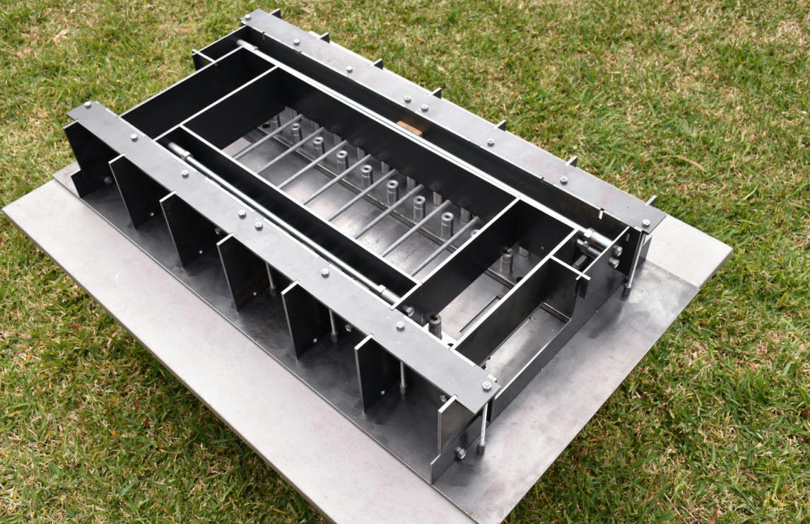
1377 forum posts 133 photos | To build this machine a surface plate will greatly assist while not essential without it much time will be wasted.
Example of how the rails will be aligned by Laser cut Then countersunk by me later cams Held by 30mm x M8 CSK machine screws, screwed into the pre turned drilled and tapped inserts glued into the lapped mounting bars. (Prior to drilling and tapping the M6 holes to mount the liner rails). This will be done after the casting has been made, small errors in placement prior to casting is easily corrected here. The cams will also make a very rigid mount for the rails. The inserts sit slightly below the surface of the scraped bars The only significant force on them is the force applied by the machine screw, they are deeply cast in, there is little chance of them pulling out.
As shown the molds are bare metal, the next step is to disassemble them then wrap the individual pieces in self adhesive plastic. This is the primary mold release it will also be coated with silicone mold release prior to casting. None of the molds have any draft. They are designed to disassemble piece by piece like a giant puzzle there are hundreds of locating tabs that keep all the parts perfectly aligned (within .1mm or better straight off the laser) There is no welding of any machine part apart from whatever tube frame is used to make the stand it sits on. I am making the cross member mold first. The images are not quite complete there are a number of small parts to be added before the first casting. I will be using the same epoxy aggregate mix I used for the epoxy warden grinder I posted here some years ago. Once cast I will post. Regards |
| David George 1 | 13/11/2018 19:24:18 |
 2110 forum posts 565 photos | I worked on a CNC mill made of composite material it was an OPS Ingersoll made in Germany and worked pretty well except before we bought it someone tried to lift it with a fork lift truck and it had slight damage to front base casting. David
Edited By David George 1 on 13/11/2018 19:29:57 |
| John McNamara | 13/11/2018 23:59:16 |
1377 forum posts 133 photos | Hi The cams allow extremely fine adjustment of the rails I have already tried this, it turns a chore into a joy, left in position they also provide very strong lateral support for the rails. The laser cut mold base plate shown was checked with a Moore & Wright 600mm precision square for squareness it was perfect by eye measurement. Measuring the piece I could find no outside the design plan errors, all was well within 0.1mm. When mounting linear rails there is a built in tolerance that allows slight adjustment after the rails are positioned. The rails I am using have 7mm counter bored holes provided, the cap head mounting bolts are M6. the hole spacing in this case is 60mm, there are a lot of holes to drill and tap. Once drilled this allows a .5mm lateral adjustment for any mounting or positioning error provided the holes are perfectly drilled and tapped on center, I have made a drilling jig to do this. without a jig it is easy to get one or two holes of center maybe binding and forcing the rail to the side. The base plate and cross member castings with their attached rails are supported by the two columns. They all have to be aligned. I considered this for some time, what is the best way to do it? My plan is to do all the alignment of the X Y and Z planes using built in adjustment of the cross member. Edited By John McNamara on 14/11/2018 00:03:16 |
| John McNamara | 14/11/2018 14:11:07 |
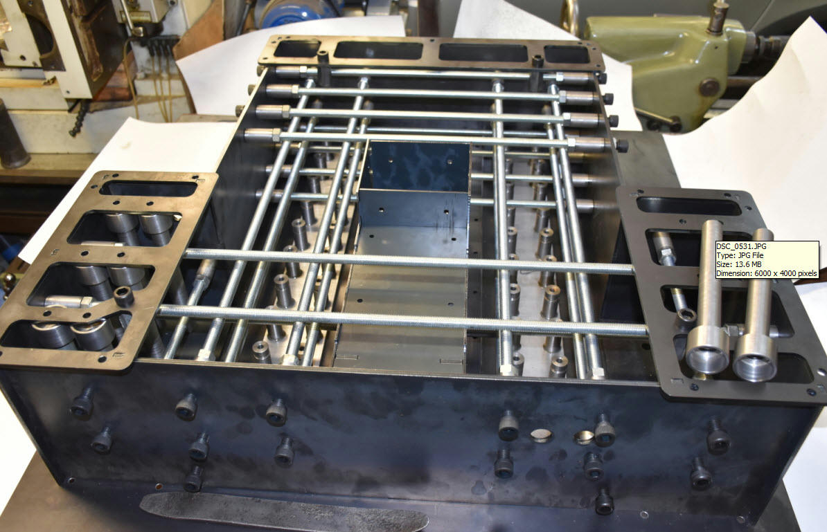
1377 forum posts 133 photos | Hi All It is important the the tapped M6 holes are accurately centered on the 7mm rail mounting holes Also note the two 2.5mm in the cams, these are for a pin wrench to allow adjustment. The cams are 4mm thick.
Accurately Drilling over 100 holes through 16mm steel plate would require a great physical effort, my bench drill press is too small. I needed a small hand drill press that I could attach to the drilling jig. Remarkably I found one at the side of the road (in Australia we have hard rubbish days once or twice a year) It was made by AEG. Perfect for what I wanted to do. I found out later they are quite inexpensive. I already had an AEG drill that fitted. The press had a base plate and 25mm steel column. I slid that off and made a new column to fit the jig as shown above, I now have proper control and the necessary leverage to drill the holes. Job done! To be cont.... Edited By John McNamara on 14/11/2018 14:15:40 |
| John McNamara | 15/11/2018 02:32:11 |
1377 forum posts 133 photos | Hi Regards Edited By John McNamara on 15/11/2018 02:42:16 |
| John McNamara | 15/11/2018 08:26:58 |
1377 forum posts 133 photos | As the cross member will be cast first it is a good time to review its components As mentioned previously built in jacks are used to position the cross member before it is epoxy/metal powder grouted in position. See red arrows below
Side View showing jacks, also the joint between the columns and the cross member, green arrows and purple and green lines. It is between these lines that the grouting will be inserted after the machine is aligned.
Alignment jacks red arrows oblique view.
To be cont.... |
| John McNamara | 15/11/2018 23:22:02 |
1377 forum posts 133 photos | How much does Epoxy cost? I did a quick google search for UK suppliers and found this example, I have no connection to the company. A 2.6 litre pack costs 36 pounds inc vat About 13.84 per litre (standard cure we do not want fast) Edited By John McNamara on 15/11/2018 23:22:32 |
| John McNamara | 17/11/2018 14:34:04 |
1377 forum posts 133 photos | Notes re laser cutting joints. The cross member and base has a laser cut steel enclosures attached that terminate the wiring, air and (water kept separate) lines and provides a base for the connectors. red arrows Also the green arrow points to the way cover blind roller brackets (hidden from view)
Some parts have been cleaned and the edges have been ground removing sharp corners. Test assembled without fastenings they just fit together. Joints
CSK joints have to be planned carefully to match the screw. 0ne standard M6 cap screw and one CSK cap screw, a firm joint. the bracket is 5mm thick mild steel Edited By John McNamara on 17/11/2018 14:34:45 |
| S.D.L. | 17/11/2018 22:17:07 |
| 236 forum posts 37 photos | This looks an interesting post, keep them coming as you can.
Steve |
| SillyOldDuffer | 18/11/2018 10:34:31 |
| 10668 forum posts 2415 photos | Threads like this leave me slack-jawed with amazement. Saying "Wow!" is the limit of my contribution. I agree with S.D.L - please keep publishing. Sometimes the better the thread the fewer the comments! Dave |
| Watford | 18/11/2018 10:54:14 |
 142 forum posts 11 photos | Absolutely and completely fascinating. Thanks for all the effort.
Mike
|
| John McNamara | 20/11/2018 10:03:34 |
1377 forum posts 133 photos | Firstly thank you for the words of encouragement Michael, Steve, Dave and Mike. and Nick from another place.
To save time the parts were laser cut as below including the 2,5mm spanner holes A simple jig was made to hold the part using the spanner holes.
Finally the hole was countersunk using the tail stock ram.
Edited By John McNamara on 20/11/2018 10:08:42 |
| SteveI | 20/11/2018 21:33:49 |
| 248 forum posts 22 photos | John,
Wonderful thread and please do keep posting, the more detail the better!
Steve |
| John McNamara | 25/11/2018 13:53:03 |
1377 forum posts 133 photos | Hi All This week I purchased 20 litres of Megapoxy H This was the epoxy I used to make the Epoxy Worden Grinder I made about 7 years ago. and published on this forum. The spec sheet for Megapoxy can be downloaded from their Australian website. I have no connection to the company apart from being a satisfied customer. Yes I am very happy to recommend them they have been most helpful. For other countries there are many companies that will offer a similar product. look for an epoxy with similar physical properties and make sure it does not contain solvents. As the name suggests solvents evaporate causing shrinkage, we do not want any mold shrinkage.
To see the casting process page down a little here: **LINK** This project was made some time ago using a simple MDF mold. Why is it that the weekend is not long enough! I had planned to pour the first casting however the few loose ends to tidy up grew. Much progress has however been made, the mold plates have been covered in plastic sheet that was in stock. Ignore the age spots, aAlso some components have been wrapped in silver vinyl duct tape. this will form a barrier stop the epoxy sticking to the steel. Before the pour the mold will also be coated with mold release Cross member mold assembled 98% As above inner frame removed
|
| Neil Wyatt | 25/11/2018 14:29:18 |
 19226 forum posts 749 photos 86 articles | Have you considered embedding tubes or even wires for stop switches and things like DRO strips directly into the cast? A magnetic scale in the surface could be very neat. Neil |
| John McNamara | 25/11/2018 14:53:25 |
1377 forum posts 133 photos |
Hi Neil Aqua blue lines are the mold. |
| John McNamara | 26/11/2018 08:16:41 |
1377 forum posts 133 photos | While i was preparing the transparent base image above I grabbed a couple of views that show the way the swarf guard blinds are set up As can be seen there is not a lot of room available in this area after the Ball screw, linear rails, limit switches and cable chain are accomodated. See earlier in the thread how the roller end brackets already laser cut are joined. aluminium swarf blinds are available commercially they have neoprene sealed joints to keep coolant out. Alternatively industrial heat resistant conveyor belting could be used, More investigation is required for the best solution at reasonable cost.
The swarf guard blinds are supported by the top of the linear rails as well as at the edges, There is also a lip at each end of the table to keep swarf out. in combination with the blind the mechanism should remain pretty clean.
This is where CAD comes into its own, every part given its own space, and not much more.
Edited By John McNamara on 26/11/2018 08:20:27 |
| martin perman | 26/11/2018 09:00:05 |
 2095 forum posts 75 photos | Many years ago, 80's, when I worked as a machine tool fitter we had grinding machine's, from memory Studer, whose bases were made from concrete, the reasoning was that manufacture was quicker and they didn't need stabilising. The mechanical's sat on inset plates which stood proud so that when the base was finished the plates could be machined to get everything level and steel plates were embedded into the base underside so that leveling feet could be fitted. Martin P |


Please login to post a reply.
Magazine Locator
Want the latest issue of Model Engineer or Model Engineers' Workshop? Use our magazine locator links to find your nearest stockist!
Sign up to our Newsletter
Sign up to our newsletter and get a free digital issue.
You can unsubscribe at anytime. View our privacy policy at www.mortons.co.uk/privacy
Latest Forum Posts
- *Oct 2023: FORUM MIGRATION TIMELINE*
05/10/2023 07:57:11 - Making ER11 collet chuck
05/10/2023 07:56:24 - What did you do today? 2023
05/10/2023 07:25:01 - Orrery
05/10/2023 06:00:41 - Wera hand-tools
05/10/2023 05:47:07 - New member
05/10/2023 04:40:11 - Problems with external pot on at1 vfd
05/10/2023 00:06:32 - Drain plug
04/10/2023 23:36:17 - digi phase converter for 10 machines.....
04/10/2023 23:13:48 - Winter Storage Of Locomotives
04/10/2023 21:02:11 - More Latest Posts...
- View All Topics
Support Our Partners


Shopping Partners
Subscription Offer

Latest "For Sale" Ads
- Reeves** - Rebuilt Royal Scot by Martin Evans
by John Broughton
£300.00 - BRITANNIA 5" GAUGE James Perrier
by Jon Seabright 1
£2,500.00 - Drill Grinder - for restoration
by Nigel Graham 2
£0.00 - WARCO WM18 MILLING MACHINE
by Alex Chudley
£1,200.00 - MYFORD SUPER 7 LATHE
by Alex Chudley
£2,000.00 - More "For Sale" Ads...
Latest "Wanted" Ads
- D1-3 backplate
by Michael Horley
Price Not Specified - fixed steady for a Colchester bantam mark1 800
by George Jervis
Price Not Specified - lbsc pansy
by JACK SIDEBOTHAM
Price Not Specified - Pratt Burnerd multifit chuck key.
by Tim Riome
Price Not Specified - BANDSAW BLADE WELDER
by HUGH
Price Not Specified - More "Wanted" Ads...
Get In Touch!
Do you want to contact the Model Engineer and Model Engineers' Workshop team?
You can contact us by phone, mail or email about the magazines including becoming a contributor, submitting reader's letters or making queries about articles. You can also get in touch about this website, advertising or other general issues.
Click THIS LINK for full contact details.
For subscription issues please see THIS LINK.
Digital Back Issues


Donate

 Register
 Log-in
Model Engineer Magazine
- Percival Marshall
- M.E. History
- LittleLEC
- M.E. Clock

ME Workshop
- An Adcock
- & Shipley
- Horizontal
- Mill

Subscribe Now
- Great savings
- Delivered to your door

Pre-order your copy!
- Delivered to your doorstep!
- Free UK delivery!
All Forum Topics > CNC machines, Home builds, Conversions, ELS, automation, software, etc tools > DIY Epoxy Frame based CNC MILL