Forum sponsored by:

Clamping
| sean logie | 12/12/2017 08:25:24 |
 608 forum posts 7 photos | I''m trying to come up with system to clamp these two plates onto the spindle carrier . I''ll be using a slitting saw to cut the slot so the plates (in theory will clamp tightly onto the spindle carrier) ,I''m going to be making spacers for between the plates ,the bottom plate will be threaded .I''m crap at describing lol . Sean |
| David George 1 | 12/12/2017 08:46:15 |
 2110 forum posts 565 photos | Hi Sean I would make an aluminium spacer with a split clamp through and then screw through the plates into the aluminium spacer to clamp the spacer between the two plates. The aluminium spacer would give bulk and carry away any heat from bearings as well. Make the aluminium spacer the same diameter as the square plates and use substantial cap screws to clamp spindle and fit a grub screw to Jack the gap open to help disembley . Hope this helps David |
| Ady1 | 12/12/2017 09:39:52 |
 6137 forum posts 893 photos | Would welding them on be an option? If you're a fan of "bigger stuff" welding can save a lot of hassle, Lidl and Aldi for example do a cheap inverter welder from time to time
Edited By Ady1 on 12/12/2017 09:42:40 |
| JasonB | 12/12/2017 10:01:35 |
 25215 forum posts 3105 photos 1 articles | You could do it without splitting and put a large grub screw in each side at the narrowest point to bear against the tube. Or if you are going to split it then just drill a hole in from one edge to the saw cut, do the same from opposite sid eand tap then use a pinch bolt to tighten it up |
| Paul White 3 | 12/12/2017 10:24:33 |
| 109 forum posts 23 photos | Given that the bearing will require some form of protection and the apparent wall thickness around the bearing, would not a bearing protector that has screw fixing into the end wall and flanged enough for the attachment by screws to the square plate cover two requirements here. Edited By Paul White 3 on 12/12/2017 10:25:58 |
| not done it yet | 12/12/2017 10:32:10 |
| 7517 forum posts 20 photos | Would welding them on be an option? No (or very little) chance with this fellow. He hates welding because of possible warping. See his previous thread on making a riser block to fit on the machine.
|
| sean logie | 12/12/2017 11:13:10 |
608 forum posts 7 photos | Thanks for all the input,welding the plates is not an option I fear ,warpage would be an issue . Aliminium spacers might be an option but will they be ridgid enough . I'm liking the grub screw at the narrowest point . The plates are a really nice snug fit on the spindle holder . Sean |
| John McNamara | 12/12/2017 13:18:33 |
 1377 forum posts 133 photos | Hi Sean I think the following sketch drawings may suggest an alternative that will give a very rigid result. Just drill and tap the front plate 4 x M12, Drill the back plate with 4x12mm holes and use M12 rod and lock nuts to carefully set the position of the plates. Now insert your spindle unit. Finally clamp two sides and a bottom to the unit to make a mould they can be anything that comes to hand, but before you attach them coat the inside surfaces with wax to stop epoxy sticking to them. OOps I have given the secret away. The unit will be filled with epoxy resin and bone dry sand, about 15% epoxy by volume, not that much really. I used this process to build a small grinder a while back. I use it almost every day to grind my lathe tools. You will notice in the second see through illustration below I have added 4 long nuts for a possible base mounting point. You can cast attachment points anywhere you choose, just screw them to your mould plates in the correct position when set just remove the screws. Regards
Edited By John McNamara on 12/12/2017 13:19:40 |
| Nick Hulme | 15/12/2017 18:46:36 |
| 750 forum posts 37 photos | Posted by sean logie on 12/12/2017 08:25:24:
I''m trying to come up with system to clamp these two plates onto the spindle carrier . I''ll be using a slitting saw to cut the slot so the plates (in theory will clamp tightly onto the spindle carrier) ,I''m going to be making spacers for between the plates ,the bottom plate will be threaded .I''m crap at describing lol . Sean Sean, |
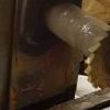
| sean logie | 04/01/2018 08:20:12 |
608 forum posts 7 photos | Made a bit more progress on the clamping for the spindle . Spacers
Cutouts for the bolts . I don't have a tap long enough to get in to thread ,so I'm going with a through nut and bolt .
Used the 3" slitting saw for the cut out and an end mill to clean up the corners .Have to say that the slitting saw blade was no where near round (new blade) ,the 2" smaller blade I have is spot on .
Sean Edited By sean logie on 04/01/2018 08:32:55 Edited By sean logie on 04/01/2018 08:33:55 |


Please login to post a reply.
Magazine Locator
Want the latest issue of Model Engineer or Model Engineers' Workshop? Use our magazine locator links to find your nearest stockist!
Sign up to our Newsletter
Sign up to our newsletter and get a free digital issue.
You can unsubscribe at anytime. View our privacy policy at www.mortons.co.uk/privacy
Latest Forum Posts
- *Oct 2023: FORUM MIGRATION TIMELINE*
05/10/2023 07:57:11 - Making ER11 collet chuck
05/10/2023 07:56:24 - What did you do today? 2023
05/10/2023 07:25:01 - Orrery
05/10/2023 06:00:41 - Wera hand-tools
05/10/2023 05:47:07 - New member
05/10/2023 04:40:11 - Problems with external pot on at1 vfd
05/10/2023 00:06:32 - Drain plug
04/10/2023 23:36:17 - digi phase converter for 10 machines.....
04/10/2023 23:13:48 - Winter Storage Of Locomotives
04/10/2023 21:02:11 - More Latest Posts...
- View All Topics
Support Our Partners


Shopping Partners
Subscription Offer

Latest "For Sale" Ads
- Reeves** - Rebuilt Royal Scot by Martin Evans
by John Broughton
£300.00 - BRITANNIA 5" GAUGE James Perrier
by Jon Seabright 1
£2,500.00 - Drill Grinder - for restoration
by Nigel Graham 2
£0.00 - WARCO WM18 MILLING MACHINE
by Alex Chudley
£1,200.00 - MYFORD SUPER 7 LATHE
by Alex Chudley
£2,000.00 - More "For Sale" Ads...
Latest "Wanted" Ads
- D1-3 backplate
by Michael Horley
Price Not Specified - fixed steady for a Colchester bantam mark1 800
by George Jervis
Price Not Specified - lbsc pansy
by JACK SIDEBOTHAM
Price Not Specified - Pratt Burnerd multifit chuck key.
by Tim Riome
Price Not Specified - BANDSAW BLADE WELDER
by HUGH
Price Not Specified - More "Wanted" Ads...
Get In Touch!
Do you want to contact the Model Engineer and Model Engineers' Workshop team?
You can contact us by phone, mail or email about the magazines including becoming a contributor, submitting reader's letters or making queries about articles. You can also get in touch about this website, advertising or other general issues.
Click THIS LINK for full contact details.
For subscription issues please see THIS LINK.
Digital Back Issues


Donate

 Register
 Log-in
Model Engineer Magazine
- Percival Marshall
- M.E. History
- LittleLEC
- M.E. Clock

ME Workshop
- An Adcock
- & Shipley
- Horizontal
- Mill

Subscribe Now
- Great savings
- Delivered to your door

Pre-order your copy!
- Delivered to your doorstep!
- Free UK delivery!
All Forum Topics > Workshop Techniques > Clamping