Forum sponsored by:

Making a new mill over arm, accurately measuring long distances?
| Rainbows | 06/09/2017 14:38:34 |
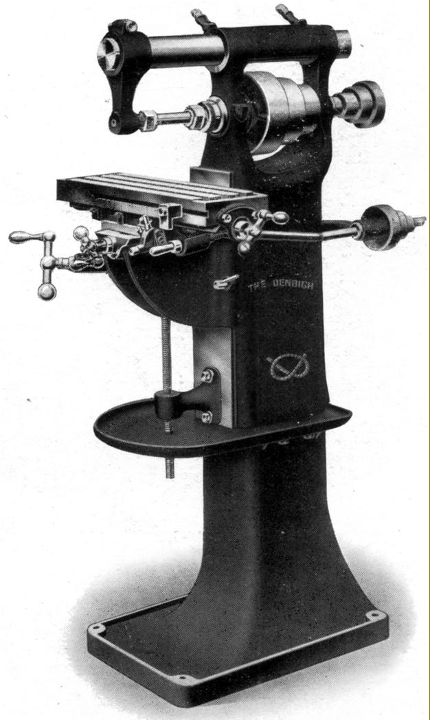
| 658 forum posts 236 photos | So for various reasons I want to make a new mill overarm. The current overarm is a cast iron tube with the arbour support cast as one with it. The quite thin walled cast iron tube is I imagine less rigid than the solid steel bar used in the alternate set up for my Denbigh mill. I want to mount a vertical milling head which means having a new over arm anyway. The existing arbour support has no convenient way to lubricate the bearing which is a slug of bronze help in place by 4 screws probably cause the person who made it had the same issue as I do right now.
I need to find the distance between the hole for the overarm and the hole for the bearing. However the distance between them is something like 182mm, to measure across the overarm and the arbour would be longer. I can't use a mic or even my calipers and I want to be chasing 0.01mm. Considering getting a 300mm caliper for £20 off fleabay so that I can at least get an approximation. Anyone know of an old engineers magic trick that can give me a very accurate measurement without resorting to buying a big expensive micrometer?
Also once I get around to building it I will probably post picture of the new arbour support here too. |
| Ian P | 06/09/2017 14:55:05 |
 2747 forum posts 123 photos | Maybe me, but I'm not clear which dimension you want to measure? Is it the centre distance between the spindle and the overarm tube centreline? Can you not miss out the measuring stages and make the overarm fit the main casting, then install it and use the spindle to machine the bearing register in situ. Not knocking your skills, but two stages of measurement increase the chances of introducing errors. Ian P
|
| Muzzer | 06/09/2017 14:55:53 |
 2904 forum posts 448 photos | I think you'd need an extremely ancient engineer to come up with a clever dodge. Realistically you will likely have to measure across outside features of the spindle and overarm, then repeat the corresponding internal dimension - then calculate the average. 300m calipers aren't going to break the bank. Something like this wouldn't break the bank. I now have some Shahe micrometers and they seem pretty good. Blame Threadexpress! Murray |
| Tony Pratt 1 | 06/09/2017 15:02:36 |
| 2319 forum posts 13 photos | Presumably your mill has micrometer dials? First make tight fitting bungs for the 2 holes, then set up the overarm on your milling table with the centres level, you will need to work out the packing required & the bores at 90 degrees to the column. You can then use a DTI to indicate the outside of one bung by raising and lowering the table to get the highest reading, zero the dial. Lower the table, move over, noting how far you are moving & do the same on the other bung without moving the DTI dial, when you get the same reading as first achieved note how far the table has moved. Use the table movement figures & bung diameters to work out the centres. Hope this makes sense? Tony |
| mgnbuk | 06/09/2017 15:09:12 |
| 1394 forum posts 103 photos | I want to be chasing 0.01mm. Considering getting a 300mm caliper for £20 off fleabay so that I can at least get an approximation. You may get an approximation with a £20 300mm caliper, but you won't be chasing 0.01mm with it ! Nigel B |
| David Standing 1 | 06/09/2017 15:28:50 |
| 1297 forum posts 50 photos | Whereabouts are you Rainbows? I have an accurate Etalon P.Roch Swiss 300mm vernier caliper you are welcome to borrow. It measures .001"/1/50mm
Edited By David Standing 1 on 06/09/2017 15:30:00 |
| Rainbows | 06/09/2017 15:41:39 |
| 658 forum posts 236 photos |
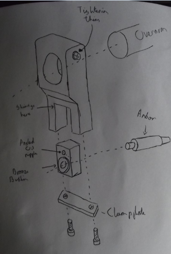
Heres some sketchbook CAD My idea for getting over the inaccuracy was having the bearing in a block that slides up and down the arbour support. Shim it into position and then securely clamp in place.
Re: boring in situ. That was my first through too and would be very good for accuracy but I can't think of any way to hold the support steady while feeding it in. There is no key in the over arm to keep it steady in place rotation wise and unlike some higher-end mills there isn't a rack and pinion to move the arm back and forth. Re: using the lead screw dials. I like the idea but I would need to invest in a coaxial indicator first I think. Other issue is I think the table might be ever so slightly shy of having enough height travel. 178mm according to lathes.co.uk though I could use a parallel to make up the difference. Re: Dave: thanks for the offer how close are you to Macclesfield? Edited By Rainbows on 06/09/2017 15:43:37 |
| Bazyle | 06/09/2017 15:42:28 |
 6956 forum posts 229 photos | If you are thinking of measuring it you have already gone wrong I'm afraid. |
| Rainbows | 06/09/2017 15:55:25 |
| 658 forum posts 236 photos | Oh damn ok I think Bazyle has got the idea. Keeping hold of a MT 3 centre that doesn't fit any of my lathes was a good idea after all.
One last thing though. If anyone has seen the turret of a capstan lathe or the tailstock of some better lathes whats the thing called that locks either the turret tool or tailstock quill in place? Its how I want to fix up the support onto the overarm but now knowing what to call it is bugging me. |
| Ian P | 06/09/2017 16:05:21 |
2747 forum posts 123 photos | Posted by Rainbows on 06/09/2017 15:41:39: Re: boring in situ. That was my first through too and would be very good for accuracy but I can't think of any way to hold the support steady while feeding it in. There is no key in the over arm to keep it steady in place rotation wise and unlike some higher-end mills there isn't a rack and pinion to move the arm back and forth. Edited By Rainbows on 06/09/2017 15:43:37One way to hold the support steady and to feed it in a controlled manner is to borrow the topslide off your lathe, fix it to the milling machine table and attach the support arm to the moving part of the slide. Not to difficult to align things and to adjust the overarm for a nice close sliding fit Ian P |
| Rainbows | 06/09/2017 16:16:13 |
| 658 forum posts 236 photos | Ah also a very good point. I really need to practice my out the box thinking more often. |
| David Standing 1 | 06/09/2017 16:21:49 |
| 1297 forum posts 50 photos | Posted by Rainbows on 06/09/2017 15:41:39:
Re: Dave: thanks for the offer how close are you to Macclesfield?
Rainbows 191 miles, to be precise! That just kyboshed that idea |
| Bazyle | 06/09/2017 18:14:12 |
6956 forum posts 229 photos | Posted by Rainbows on 06/09/2017 15:55:25:One last thing though. If anyone has seen the turret of a capstan lathe or the tailstock of some better lathes whats the thing called that locks either the turret tool or tailstock quill in place? Its how I want to fix up the support onto the overarm but now knowing what to call it is bugging me.
Cotter pin. As used on bicycle cranks at one time. By the way it is important when making a cotter to think a bit about how it works. Sometimes it is suggested that you fit the pin then drill through the shaft hole to take a curved slice out of the pin that 'fits the shaft perfectly' so will lock it nicely. However what then actually happens is the 'heal' of the scallop taken from the pin dents the shaft as it is pulled up tight. You need a gentle slope as used on those bicycle ones. |
| Rainbows | 06/09/2017 19:29:25 |
| 658 forum posts 236 photos | Ahh I thought cotter pin but when I googled it there was just the hairpin style ones. Yeah I was about to make it in situ with the rest of the hole. I would have thought the single line of contact in the wedge shape would give more pressure -> more chance of denting? Maybe if I bore it in situ and then file off the small extremity of the pin it will give the best of both worlds? |
| Dave Halford | 06/09/2017 19:40:18 |
| 2536 forum posts 24 photos | Posted by Bazyle on 06/09/2017 15:42:28:
If you are thinking of measuring it you have already gone wrong I'm afraid. Exactly what I did to re set my Centec way, way waaay out of alignment overarm bearing. |
| Tony Pratt 1 | 06/09/2017 20:13:12 |
| 2319 forum posts 13 photos | Posted by Rainbows on 06/09/2017 19:29:25:
Ahh I thought cotter pin but when I googled it there was just the hairpin style ones. Yeah I was about to make it in situ with the rest of the hole. I would have thought the single line of contact in the wedge shape would give more pressure -> more chance of denting? Maybe if I bore it in situ and then file off the small extremity of the pin it will give the best of both worlds? Logic dictates that a full contact radius cotter will give a better grip than a wedge, judicious chamfering may be needed to prevent 'dig in'. I would suggest a wedge cotter is used in most cases as all pins and shafts of the same size will be interchangeable? Tony |
| mark costello 1 | 06/09/2017 20:21:20 |
 800 forum posts 16 photos | I gave up on bushings on mine and made a new arm with ball bearings, problem solved. |
| peak4 | 06/09/2017 20:47:54 |
 2207 forum posts 210 photos | Posted by David Standing 1 on 06/09/2017 16:21:49:
Posted by Rainbows on 06/09/2017 15:41:39:
Re: Dave: thanks for the offer how close are you to Macclesfield?
Rainbows 191 miles, to be precise! That just kyboshed that idea Rainbows, I however now live in Buxton,which is a wee bit closer to Mac. I also recently bought a 24" vernier calliper of reasonable quality; that's manual reading vernier, as opposed to new fangled digital electronic stuff.
Drop me a PM for the address and pop over for a brew sometime. Regards Bill |
| steamdave | 06/09/2017 22:14:59 |
| 526 forum posts 45 photos | If you have or can borrow a copy of GHT's book on making the Universal Pillar Tool, he explains how to make a cotter. They are used to hold the arms to the column and column to base. Dave |
| not done it yet | 06/09/2017 22:37:25 |
| 7517 forum posts 20 photos |
So what is wrong with the current arbor support? Bore out the over arm innards and fit to a spigot on the new overarm. No real meaurement required. Sort the arbor lubrication with a suitable mod - like an oil hole? KISS Principle working again?
|

Please login to post a reply.
Magazine Locator
Want the latest issue of Model Engineer or Model Engineers' Workshop? Use our magazine locator links to find your nearest stockist!
Sign up to our Newsletter
Sign up to our newsletter and get a free digital issue.
You can unsubscribe at anytime. View our privacy policy at www.mortons.co.uk/privacy
Latest Forum Posts
- hemingway ball turner
04/07/2025 14:40:26 - *Oct 2023: FORUM MIGRATION TIMELINE*
05/10/2023 07:57:11 - Making ER11 collet chuck
05/10/2023 07:56:24 - What did you do today? 2023
05/10/2023 07:25:01 - Orrery
05/10/2023 06:00:41 - Wera hand-tools
05/10/2023 05:47:07 - New member
05/10/2023 04:40:11 - Problems with external pot on at1 vfd
05/10/2023 00:06:32 - Drain plug
04/10/2023 23:36:17 - digi phase converter for 10 machines.....
04/10/2023 23:13:48 - More Latest Posts...
- View All Topics
Support Our Partners


Shopping Partners
Subscription Offer

Latest "For Sale" Ads
- Reeves** - Rebuilt Royal Scot by Martin Evans
by John Broughton
£300.00 - BRITANNIA 5" GAUGE James Perrier
by Jon Seabright 1
£2,500.00 - Drill Grinder - for restoration
by Nigel Graham 2
£0.00 - WARCO WM18 MILLING MACHINE
by Alex Chudley
£1,200.00 - MYFORD SUPER 7 LATHE
by Alex Chudley
£2,000.00 - More "For Sale" Ads...
Latest "Wanted" Ads
- D1-3 backplate
by Michael Horley
Price Not Specified - fixed steady for a Colchester bantam mark1 800
by George Jervis
Price Not Specified - lbsc pansy
by JACK SIDEBOTHAM
Price Not Specified - Pratt Burnerd multifit chuck key.
by Tim Riome
Price Not Specified - BANDSAW BLADE WELDER
by HUGH
Price Not Specified - More "Wanted" Ads...
Get In Touch!
Do you want to contact the Model Engineer and Model Engineers' Workshop team?
You can contact us by phone, mail or email about the magazines including becoming a contributor, submitting reader's letters or making queries about articles. You can also get in touch about this website, advertising or other general issues.
Click THIS LINK for full contact details.
For subscription issues please see THIS LINK.
Digital Back Issues


Donate

 Register
 Log-in
Model Engineer Magazine
- Percival Marshall
- M.E. History
- LittleLEC
- M.E. Clock

ME Workshop
- An Adcock
- & Shipley
- Horizontal
- Mill

Subscribe Now
- Great savings
- Delivered to your door

Pre-order your copy!
- Delivered to your doorstep!
- Free UK delivery!
All Forum Topics > Workshop Tools and Tooling > Making a new mill over arm, accurately measuring long distances?