Forum sponsored by:

Making a Dickson style QCTP
| Rainbows | 08/08/2017 05:00:21 |
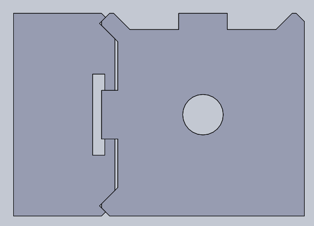
| 658 forum posts 236 photos | As a first involved project in the new horizontal mill I wanted to make a toolpost, first a small practice one for the mini lathe then a larger one for the keighley. The horizontal mill suits making the profile in a dickson much better than it makes dovetails like most home made QCTPs.
Just need to check one thing first since its been a while since I used a dickson and I didn't properly pay attention to it.
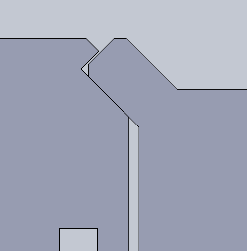
Does the toolholder seat on 4 faces (top pic) or two faces (bottom pic where there is clearance on the outside face). I would imagine 4 faces would over constrain the part, but then why both with the extra angles? |
| Tony Pratt 1 | 08/08/2017 07:22:25 |
| 2319 forum posts 13 photos | I believe 2 mating faces would be adequate & trying to match 4 in an amateur setting would be a lesson in frustration to no purpose. I await the different answers with anticipation. Edited By Tony Pratt 1 on 08/08/2017 07:39:04 |
| JasonB | 08/08/2017 07:56:26 |
 25215 forum posts 3105 photos 1 articles | Just tried a 0.002" feeler gauge and can't get that in the outer face so I would say they touch. |
| Tony Pratt 1 | 08/08/2017 09:21:32 |
| 2319 forum posts 13 photos | Posted by JasonB on 08/08/2017 07:56:26:
Just tried a 0.002" feeler gauge and can't get that in the outer face so I would say they touch.
Well less than .002" apart |
| JasonB | 08/08/2017 09:36:08 |
25215 forum posts 3105 photos 1 articles | I think if I blued them then they would show mating surfaces, as rainbows says why go to the effort of machining the return ends if they were not intended to touch. As you say it may not be critical for hobby machine loadings. |
| Mike Crossfield | 08/08/2017 09:59:44 |
| 286 forum posts 36 photos | I made some extra toolholder for my Dickson tool post a while back, and the originals did indeed contact on all 4 faces (checked with blue). With care and a little final scraping I managed to get my copies to contact similarly. |
| KWIL | 08/08/2017 10:13:09 |
| 3681 forum posts 70 photos | I would suggest that the 4 contact faces are the esential element, if it was not part of the design that all 4 faces make contact then the outer 2 would not have been necessary. Cannot lay my hands on the Engineers Blue tin at present but I am sure a simple test would show contact on all 4. I have made my own, for specialist appllications and used the blue method to ensure full contact. A decent DRO on the Y axis should get you very close. Edited By KWIL on 08/08/2017 10:13:37 |
| Muzzer | 08/08/2017 10:31:44 |
 2904 forum posts 448 photos | Posted by Rainbows on 08/08/2017 05:00:21:
Does the toolholder seat on 4 faces (top pic) or two faces (bottom pic where there is clearance on the outside face). I would imagine 4 faces would over constrain the part, but then why both with the extra angles? That is my belief, having also made up a mating toolholder (for a DTI) for my genuine Dickson post. As you say, the only correct toolholder would require zero tolerances and the assembly would be overconstrained / statically indeterminate / impossible to analyse. Manually lapping them in would seem to be a partial solution but mine didn't appear to have been lapped. It's ironic that such a "well engineered" design should be almost impossible to make correctly. Very British? I suspect this is one (of several) reason why clone toolholders rarely fit properly out of the box - that and no published drawings of course. I seem to recall that it was a bit of a bu99er to draw up, dimension and set up - where to position the datum(s) when there are so many 45 degree faces etc. It may only be the way you modelled the toolpost but IIRC the tongue you have shown extending into the tee slot only pulls the toolholder against the vees - it's loose and cannot provide lateral location. Murray |
| Clive Foster | 08/08/2017 12:18:41 |
| 3630 forum posts 128 photos | Took a quick look through my collection of Dickson / high quality (Rapid et al) clone T2 size posts and toolholders. The most common contact areas are easily identified by looking for polished sections on the male Vees on the post. As would be expected from proper analysis of the design the outside of the post Vees shows most polishing indicating that this is where the tool holders usually touch. Harder to see on the holders themselves but some show polishing inside. Careful observation of the holders often makes it clear where contact occurs. It does vary but not greatly. Regrettably I find it necessary to cross pens (keyboards) with the redoubtable Murray concerning the standard of engineering of the Dickson post and its apparent need for impossible precision to achieve full contact on four Vee faces. In fact twin parallel male and female Vee guides are remarkably tolerant when it comes to secure, shake free location. If working to normal engineering tolerances on a geometrically viable design its essentially impossible to create such a system that doesn't achieve the three point contact necessary for stability. Providing the Vees are parallel to close limits line contact, as per the bevelled edge Webster-Whitcombe style watchmakers lathe bed, will be achieved over the widely spaced opposite hand Vee surfaces clearly improving stability over single Vee guidance as per the common Vee flat lathe bed. Either inner or outer pairs will work fine but, if mine are typical, outer is normal. Although parallelism of the Vee surfaces is the only exceptional constraint for accurate, secure, location it is clearly sensible to get the spacing and angles right to reasonably close limits too. Common grinding tolerances being more than adequate. Given a modicum of operator care in set-up and operation shaper or planer will do the Vee job just fine. All other QC systems have two close constraint limits which must be met if accuracy and security is to be achieved. So in that respect at least the Dickson is a superior design. Clamping is the achilles heel of the Dickson concept. The internal Tee slot is moderately tricky to produce and there is considerable scope for wrong way tolerance build up in the various components of the rotating locking cam device and the mutual height / depth of the Vees on holder and post. Analysis shows the allowable range is actually quite wide. Maybe 20 thou per 10° rotation of the locking cam spanner. There is no reason why competent manufacturers who understand what they are doing cannot produce clone systems with satisfactory mix'n match performance. Which is indeed the case for the professional end of the market. I've yet to see a combination which doesn't work between, probably, half a dozen breeds save for a minor, but profoundly irritating, variation in height setting thimble dimensions. Contemplating why paired Vee guides were used rather than simple beveled edges, which would functionally be the same, makes an interesting exercise for the gentle reader. I have several ideas but would not presume to know the real reason. Intuitively it seems more right and, in use, maybe better able too cope with swarf. If I were making my own I'd make the clamping tongue on the holder a separate part glued and screwed into place. Much easier than that slot. Making and measuring to tolerance would be a snap that way. If doing it properly and cutting the slot from solid probably best to do the slot first and jig up against the clamping surface when mounting up for the Vees. Clive. Edited By Clive Foster on 08/08/2017 12:20:36 |
| Neil Wyatt | 08/08/2017 12:28:05 |
 19226 forum posts 749 photos 86 articles | You could get the repeatability of the Dickson with less challenging machining simply by only having a double-sided V at one end of the toolholder. I can't see how it would compromise rigidity, as it would always contact fully on three surfaces, assuming you machine them at one setting. Neil |
| JasonB | 08/08/2017 12:40:19 |
25215 forum posts 3105 photos 1 articles | Or half round sections on the too lpost that the vees would sit on of all were parallel.
A rough and ready swipe with a marker and a bit of rubbing shows that my genuine holders make most contact at the ends of the inner faces.
This is marked in red on the post but there is a faint hint of blue on the rest of the surface and also the outer ones. Must stone down those 3 marks top left as they seem to leave a scratch in the blue.
|
| Clive Foster | 08/08/2017 12:53:09 |
| 3630 forum posts 128 photos | Neil Sorry, nope! End up with a narrow guide system which is less rigid. Harder to machine too as its a Vee - flat system like a conventional lathe bed. Vee - flat system constraints are horrible if you want secure, accurate interchangeably. Four precision constraints on each part, all struck off a master plane. There is a reason why lathe beds and saddles have, historically, always been scraped to fit as pairs. SouthBend, past masters of inexpensive precision knew exactly what they were doing in using twin Vees on their beds. If you want a single Vee then the other side needs to be flat against a part spherical curve. Not nice in that sort of job for many reasons. The whole point of the Dickson system is that, in principle, it requires only that the Vees be parallel and the overall layout geometrically sensible. Clive. |
| JasonB | 08/08/2017 13:03:03 |
25215 forum posts 3105 photos 1 articles | Posted by Clive Foster on 08/08/2017 12:53:09:
The whole point of the Dickson system is that, in principle, it requires only that the Vees be parallel and the overall layout geometrically sensible. Clive. Clive surely if they were only parallel but different distances apart you would only get poor contact on 3 of the 4 surfaces as the holder would tend to pull down onto one of the pair better than the other which would tend to cock it at an angle. |
| Clive Foster | 08/08/2017 14:02:06 |
| 3630 forum posts 128 photos | Jason The Dickson system only requires simultaneous contact between two of the widely spaced Vee surfaces for best operation. It behaves much like the bevelled edge Webster-Whitcombe stye watchmakers lathe bed. It doesn't really matter whether its the inner or outer pairs doing the work. In any one post - holder assembly the other two surfaces are, so to speak, in the wind and just along for the ride. Having two Vees basically means that if, depending on tolerance build up, one pair doesn't contact the other will. As Murray said earlier, four surface contact is over-constraint and unnecessary difficult to achieve in production. In practice you generally do get some degree of 3 or 4 surface contact with good quality holders and posts but its not essential. Probably good test of production quality. It is possible to get one Vee doing most of the work using both sides with just a bit of support from a point or two on the other one. I suspect that is functional but not ideal. From a manufacturing perspective its all about interchangeability. Ideally you want all the tolerances and constraints within the natural capability of your manufacturing processes. If that can't be managed then you need to minimise the number of really precise operations. If you think about the Dickson system provided the Vees are parallel its still going to give you decent two edge contact despite small variations of Vee spacing, angle and depth. If one pair is a bit too far apart then the outer edges contact, if too close the inner ones. In practical world the permissible variations are probably larger than any competent maker would turn out. Its the clamp system that bites as being very vulnerable to tolerance build up. Vee spacing, width and depth errors can add up. Not to mention the thickness of the holder tongue and all the locking device bits. Coping range is plenty for single maker systems but between makes is harder. The stability of this sort of set up is crudely defined by the area of the plane surface defined by straight lines between the most widely separated contact points. Ignoring pesky details like contact pressure and geometrical equivalence its clear that the Dickson layout is one of the better ones when it comes to coping with tolerance variations whilst still giving a nice set of widely spaced contact points. I've heard said that this is almost a weakness of the Dickson system because large contact areas and correspondingly low contact pressures are commonly achieved making them prone to vibration loosening with hefty interrupted cuts. My experience is that fine swarf build up inside is a more likely cause of loosening. Mine pick up a stupid amount of dusty, uber small swarf stuff. Clive. Edited By Clive Foster on 08/08/2017 14:04:51 Edited By Clive Foster on 08/08/2017 14:06:15 |
| larry Phelan | 08/08/2017 14:08:13 |
 544 forum posts 17 photos | I think I,ll stick to my common or garden 4 way tool post. |
| Muzzer | 08/08/2017 14:21:01 |
2904 forum posts 448 photos | Yes, I have to admit that am not convinced by the fundamental concept behind the Dickson toolpost, having used mine for 20-odd years. The preload on the toolholder is set by the (elastic) deflection of the cam - and once that is overcome, movement between the holder and post will follow, usually when least appreciated. Call me an engineering coward if you like but my solution was to cough up for a Multifix / 40-position toolholding system from Create Tool. It's not a concept that would be easy to analyse but to my mind the system of mating cylindrical features seems to promise much firmer locking with the same force applied by the cam mechanism. One downside is that I wouldn't attempt to make my own toolholders... I was also sceptical about how the loads are withstood and movement prrevented as their point of application and magnitude vary with the Dickson system. Being held between 2 perpendicular faces some distance apart doesn't seem the obvious solution. It lacks any well defined register or similar feature. Murray |
| KWIL | 08/08/2017 14:40:57 |
| 3681 forum posts 70 photos | Yes Larry, a 4 way toolpost is fine if you only need 4 tools in any one session and do not have to change them. If you do multiple operations then having a set of preset tools in QCTP holders enables a rapid change in seconds without the need to adjust height everytime. |
| Tony Pratt 1 | 08/08/2017 14:45:21 |
| 2319 forum posts 13 photos | Interesting topic, I don't suppose the Dickson is perfect but better than some other offerings. I personally have had a tool holder come loose when cutting on a couple of occasions,makes for a butt clenching few seconds. Tony |
| David Standing 1 | 08/08/2017 14:51:42 |
| 1297 forum posts 50 photos | Posted by KWIL on 08/08/2017 14:40:57:
Yes Larry, a 4 way toolpost is fine if you only need 4 tools in any one session and do not have to change them. If you do multiple operations then having a set of preset tools in QCTP holders enables a rapid change in seconds without the need to adjust height everytime.
And depending what multiple tasks you are carrying out, a 4 way toolpost is at best only likely to enable you to mount two, or maybe, three cutters in it anyway. |
| Saxalby | 08/08/2017 16:10:23 |
 187 forum posts 33 photos | I have used a Dickson tool post on my Boxfords for some 30 years and have never had a holder come loose or fail to fit properly. The holders (15) are mixtures those bought from Boxford, auto jumbles and few I have made myself. Those I made myself. I measured a Dickson holder, roughed out on the vertical mill and then finished the "V"s with a 90 deg cutter on the horizontal spindle of the Tom Senior. No problem with fit, just need to measure the "V"s separation and depth as accurately as you can.
Regards Barry |


Please login to post a reply.
Magazine Locator
Want the latest issue of Model Engineer or Model Engineers' Workshop? Use our magazine locator links to find your nearest stockist!
Sign up to our Newsletter
Sign up to our newsletter and get a free digital issue.
You can unsubscribe at anytime. View our privacy policy at www.mortons.co.uk/privacy
Latest Forum Posts
- *Oct 2023: FORUM MIGRATION TIMELINE*
05/10/2023 07:57:11 - Making ER11 collet chuck
05/10/2023 07:56:24 - What did you do today? 2023
05/10/2023 07:25:01 - Orrery
05/10/2023 06:00:41 - Wera hand-tools
05/10/2023 05:47:07 - New member
05/10/2023 04:40:11 - Problems with external pot on at1 vfd
05/10/2023 00:06:32 - Drain plug
04/10/2023 23:36:17 - digi phase converter for 10 machines.....
04/10/2023 23:13:48 - Winter Storage Of Locomotives
04/10/2023 21:02:11 - More Latest Posts...
- View All Topics
Support Our Partners


Shopping Partners
Subscription Offer

Latest "For Sale" Ads
- Reeves** - Rebuilt Royal Scot by Martin Evans
by John Broughton
£300.00 - BRITANNIA 5" GAUGE James Perrier
by Jon Seabright 1
£2,500.00 - Drill Grinder - for restoration
by Nigel Graham 2
£0.00 - WARCO WM18 MILLING MACHINE
by Alex Chudley
£1,200.00 - MYFORD SUPER 7 LATHE
by Alex Chudley
£2,000.00 - More "For Sale" Ads...
Latest "Wanted" Ads
- D1-3 backplate
by Michael Horley
Price Not Specified - fixed steady for a Colchester bantam mark1 800
by George Jervis
Price Not Specified - lbsc pansy
by JACK SIDEBOTHAM
Price Not Specified - Pratt Burnerd multifit chuck key.
by Tim Riome
Price Not Specified - BANDSAW BLADE WELDER
by HUGH
Price Not Specified - More "Wanted" Ads...
Get In Touch!
Do you want to contact the Model Engineer and Model Engineers' Workshop team?
You can contact us by phone, mail or email about the magazines including becoming a contributor, submitting reader's letters or making queries about articles. You can also get in touch about this website, advertising or other general issues.
Click THIS LINK for full contact details.
For subscription issues please see THIS LINK.
Digital Back Issues


Donate

 Register
 Log-in
Model Engineer Magazine
- Percival Marshall
- M.E. History
- LittleLEC
- M.E. Clock

ME Workshop
- An Adcock
- & Shipley
- Horizontal
- Mill

Subscribe Now
- Great savings
- Delivered to your door

Pre-order your copy!
- Delivered to your doorstep!
- Free UK delivery!
All Forum Topics > General Questions > Making a Dickson style QCTP