Forum sponsored by:

Using Toolmakers Buttons
| SillyOldDuffer | 05/02/2017 19:10:40 | ||
| 10668 forum posts 2415 photos | I've been reading a book that describes how to accurately position holes using buttons. Basically, I think it says:
It's very possible I 've misunderstood the book, but the method seems to rely on correcting a mildly inaccurate pilot hole by boring it out. My smallest boring bar starts at 9mm diameter. Does that mean that the method isn't suitable for accurately positioning small holes, or am I missing sometjhing? Thanks, Dave
Edited By SillyOldDuffer on 05/02/2017 19:12:55 | ||
| JasonB | 05/02/2017 19:14:08 | ||
 25215 forum posts 3105 photos 1 articles | You could always make the first trueing cut with a 2 or 3 flute milling cutter held in the tailstock which should be less likely to fiollow the wayward pilot hole than a drill.
J | ||
| Carl Wilson 4 | 05/02/2017 19:20:28 | ||
 670 forum posts 53 photos | I'm not sure I understand what you are saying about using the milling cutter in the tailstock. Less likely to follow the path of the inaccurate first pilot hole...That's not too reassuring. Kind of negates the centring with the button etc. I'm sure I've got it wrong. | ||
| geoff walker 1 | 05/02/2017 19:21:58 | ||
| 521 forum posts 217 photos |
That's the way to do it, keep the center fixing screw as small as is practical
| ||
| John Reese | 05/02/2017 19:42:08 | ||
 1071 forum posts | Don't let the 9mm bar limit you. You can buy or make much smaller bars. You can grind one out of a square tool bit or an old end mill. The standard screw for toolmakers buttons made by Starrett or Brown and Sharpe was 5-40 (1/8" dia.) I suppose a smaller screw could be substituted. the smallest bored hole when using buttons would be one that just removed the pilot hole. +1 on using an end mill to true the hole before boring to size. It is short and rigid. Its square end will not follow the pilot hole. | ||
| MalcB | 05/02/2017 20:05:24 | ||
| 257 forum posts 35 photos | We used toolmakers buttons in the toolroom/toolroom inspection as follows: Toolmakers making complex drilling jigs would mark out hole positions for the drill bushes using height gauges and the like in relation to the component to be drilled location surfaces and pads etc. Toolmaker would drill and tap through each hole about 2-4BA etc where the drill bushes were to be positioned. Buttons would then be secured to each tapped hole ( plenty of clearance twixt buttons and fixing screws ). Jig would be sent into tool inspection area/department. Jig would then be very accurately set up by a tool inpector and all the buttons Precisely positioned accordingly. Set up datums would be identified for the jig body. Jig then moved on to jig borer. Jig borer setting up to inspector identified datums. Jig borer would usually set up true to each individual button one at a time. Jig borer would then slot drill and then with boring bar finish to to suit outside diameter of slip bush for drill bushes. Back into tool inspection for final checks. By complex jigs, I refer to those where the jig borer found it difficult or impossible to get at the components location faces and pads etc directly.
Edited By MalcB on 05/02/2017 20:06:51 | ||
| Dusty | 05/02/2017 20:08:50 | ||
| 498 forum posts 9 photos | The first question I must ask is how small do you want to make your hole? If you are not going to bore your hole then there is not a lot of point using buttons, I would think that probably 5/32" or 4mm is about the smallest you can use this technique on. As Jason has said a slot drill in the tailstock chuck and fed in very carefully will hopefully give you a hole that is somewhere near its required position, but do not take that as gospel. My buttons screws have been replaced with 5ba. I have also made larger dia buttons for particular jobs the only requisite is they have a face and dia that are square to one another, the size maters not a jot as long as you know what it is for setting. Your understanding of their use is O.K. | ||
| Hopper | 06/02/2017 07:46:04 | ||
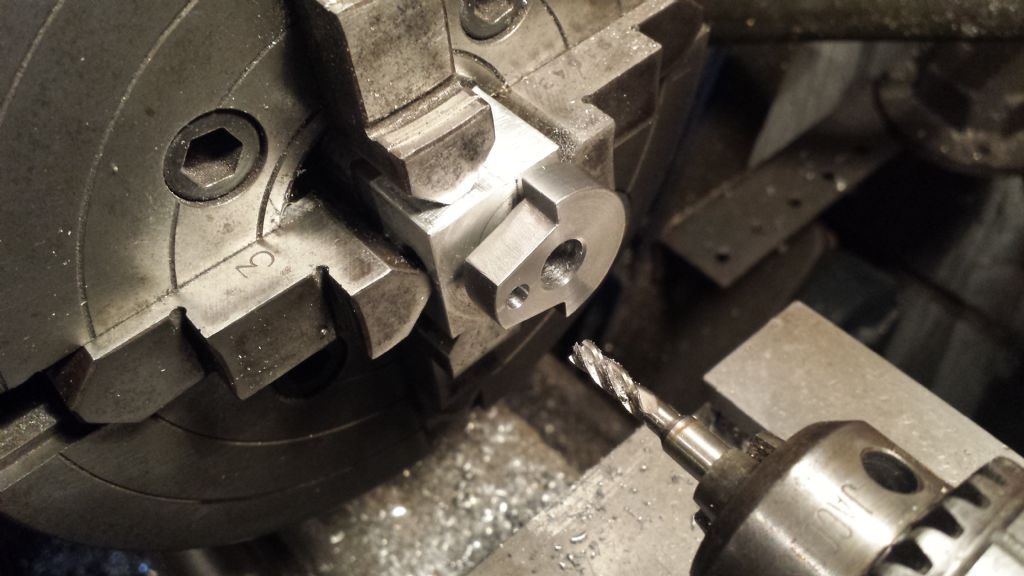
 7881 forum posts 397 photos | If you locate the original threaded hole somewhere near where you want the centre of the finished hole to be, you can just drill it out with a drill that is somewhat under the finished size of the hole. Does not matter if it is slightly off centre, as long as the hole is big enough to fit your boring bar into but small enough that it does not break out of the desired location of the finished hole. So, for instance, you might use a 3/16 tapped hole to locate the toolmaker's button to correctly locate a 1/2" hole. So once the job is set in position, you drill the tapped hole out with a 3/8 drill, even if it wobbles about say 1/32" off centre. Then when you stick your boring bar in there and clean up the hole to 1/2", the boring bar will cut true to the centre of rotation rather than follow the wobbly hole. | ||
| Neil Lickfold | 06/02/2017 08:12:25 | ||
| 1025 forum posts 204 photos | Toolmakers buttons are useful in situations where it is not easy to find the datum on the machine tool and need the hole or detail to be accurately placed. There are many ways of using them. It does not have to be for boring a hole. They can be used also as a reference position when milling pockets or other details. any hole from m3 and up can be used. I have used an M2 on one job before. The buttons are easy to use and make. The most important part of them is knowing it's size. making a series of a nominal size and all the same is very convenient when using gauge blocks or set standard lengths etc. Now days the tool makers buttons are being replaced by reference holes that are precision placed etc. These are then latter referenced like a toolmakers button is. Neil | ||
| Nigel McBurney 1 | 06/02/2017 09:10:24 | ||
 1101 forum posts 3 photos | Another use of the button principle is to accurately set out gear centres, machine special buttons ,the o/dia being a good fit in the bore of the gear drill the small tapped holes in the work to the approximate position of the gears ,then fit the gears on the buttons and check the mesh,if too tight or too much backlash one of the buttons can be slightly moved to adjust the mesh,then the holes bored . I laid out the shaft centres on the horn plates of my Allchin t/e using this method starting at the crankshaft and working down to the rear axle. | ||
| Ian S C | 06/02/2017 10:12:57 | ||
 7468 forum posts 230 photos | Here's one made for a job years back from a bit of 1/4" squ HSS, its still in regular use, when first made it went in a 3/16" hole, now the end looks more like a D bit, and it will go easily int a 1/8" hole. Ian S C | ||
| IanT | 06/02/2017 10:21:58 | ||
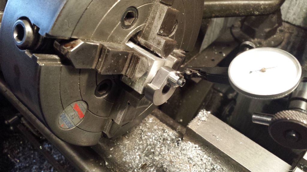
| 2147 forum posts 222 photos | SD "Duffer" For small holes you do not need to fully bore the tapped hole to correct it. It can be done with a graver or better still (if somewhat cack-handed & short sighted like me) a slim 'pointy' tool held at centre height in the tool holder. The aim is to come in at a 30 degree angle and effectively chamfer the edge of the previously drilled/tapped hole - which if correctly marked out in the first place should not be too much out anyway. This will true the hole and help guide the following drill in about as accurately as you can do so. I'd use a new drill for the job if possible. I've done this on a set of gearbox plates where I wanted the mesh to be as good as I could get it and I didn't have a small enough boring tool for the holes required (and frankly was too idle/impatient to make one). It's exactly like using a slocome (centre) drill to start the hole but where you know the 'cone' will be dead on if done carefully. My old S7 tailstock has quite a bit of droop in it - so it's not ideal for really accurate drilling and sometimes needs my help. Obviously, fully boring the hole out is the better option but this is a workable alternative. By the way - you describe drilling just a single hole and generally for that I'd just use an optical punch to get the best 'dimple' I could, centre the work from that and then just centre drill it. If I was really worried about accuracy (for the reasons previously given) a quick truing/coning cut helps reassure me. Traditional "buttons" are sets of the same diameter as described by another poster (with one long one) but I've not really needed a set of this kind that I can recall. The 'buttons' I have used have generally been turned to a specific size to set the relationship between holes (or other reference points/edges) as well as I could get it given my antique machinery. For instance, for the gearbox mentioned, buttons were turned to the gear PCDs (which I could check with a micrometer) and then screwed to the work touching each other - obviously the first one set has to be slightly longer. I also use a form of simple button when I have work with a existing hole in it that I need to centre. Maybe it's not called a "button" but to my mind, it's a button with a turned stub (to fit the hole) that can be clocked in exactly the same way to centre the work. Not the way it's done in industry (or by others here) perhaps but I'm afraid I don't have a jig borer or a mill with DROs, so these simple dodges help.... Regards,
IanT | ||
| SillyOldDuffer | 06/02/2017 11:46:13 | ||
| 10668 forum posts 2415 photos | I'm tickled pink by the range and quality of answers to this question. New things learned by me include:
Many thanks, Dave | ||
| Tony Pratt 1 | 06/02/2017 11:59:12 | ||
| 2319 forum posts 13 photos | Posted by IanT on 06/02/2017 10:21:58:
Not the way it's done in industry (or by others here) perhaps but I'm afraid I don't have a jig borer or a mill with DROs, so these simple dodges help.... Regards, IanT Hi Ian, I'm curious about your statement ,'mill with DRO's', if presumably you have a mill with dials that's all you need to successfully position holes to a fair degree of accuracy. Tony
| ||
| IanT | 06/02/2017 14:02:14 | ||
| 2147 forum posts 222 photos | Hallo Tony, Yes, of course accurate positioning is possible on a mill without DROs. I often see reference to them here and I am sure they do make life much easier when fitted and that's certainly the impression I get. But I try to comment within the context of what I know and do myself, in the hope that this will be useful to others who might have similar constraints to mine (in either their skill levels or available machinery). For many years, my workshop was 'lathe only', so my work - mostly small models and any required tooling, jigs (plus the odd washing machine part) had to be achieved within those constraints. I now effectively have three milling machines - a large horizontal (Victoria), a benchtop horizontal (Atlas MF) and a Taig (lathe mounted) vertical head, with both horizontals having vertical milling heads fitted. However, none of these machines are mill/drills - in the sense that they do not have drilling 'quills' with all vertical movement being via the knee, so drilling with them is just about doable but not exactly ideal. Also, there is considerable wear and backlash in the two larger machines (that hopefully I will fix one day) but that I currently just "live with". My larger machines are also in the "cold" workshop that I don't get into too much in the winter, so again my small 'inside' lathe gets used for a lot of things than it might otherwise not do. So that is my "context" if you wish - the background against which I try to help some here... So sure, I could use a mill (and it's dials) to do this work but I guess that if the work will fit in the four jaw or on the faceplate (and most of my work will do so) then that's what I tend to prefer to do, partly because I'm used to doing it way and partly because my mills are not ideal for this (though they are very useful for other things of course!). People with newer (vertical) mills, that generally have drilling quills, will quite likely have their own preferences and of course a CNC 'miller' will just pop in the co-ordinates and drill away. Good luck to them, they are very fortunate to have these facilities but I don't I'm afraid and probably never will have now. So to be clear - I wasn't trying to have a dig at anyone who is lucky enough to have a jig borer or DRO equipped mill - I was just suggesting that some folk here will need to find other ways to do some things and suggesting ways to do them. Regards,
IanT | ||
| MalcB | 06/02/2017 15:04:27 | ||
| 257 forum posts 35 photos | My two sets of toolmaker buttons: | ||
| Tractor man | 06/02/2017 15:42:35 | ||
| 426 forum posts 1 photos | I picked two sets of four of these up tother day. Thay will come in handy at some point I'm sure. | ||
| Gordon W | 06/02/2017 15:51:14 | ||
| 2011 forum posts | For those of you, like me, who don't have the proper buttons-- Use ball races of whatever size is best. Old and worn races will do., a suitable washer to clamp. | ||
| SillyOldDuffer | 06/02/2017 15:53:34 | ||
| 10668 forum posts 2415 photos | Posted by MalcB on 06/02/2017 15:04:27:
My two sets of toolmaker buttons: IanT mentioned that one of the buttons was longer than the others and there's the proof in your picture. But why is one button longer than the others in a set? Ta, Dave | ||
| Andrew Johnston | 06/02/2017 16:23:45 | ||
 7061 forum posts 719 photos | Posted by SillyOldDuffer on 06/02/2017 15:53:34:
But why is one button longer than the others in a set? So it can be set, or indicated, when other button(s) are close by. Andrew |
.jpg")

Please login to post a reply.
Magazine Locator
Want the latest issue of Model Engineer or Model Engineers' Workshop? Use our magazine locator links to find your nearest stockist!
Sign up to our Newsletter
Sign up to our newsletter and get a free digital issue.
You can unsubscribe at anytime. View our privacy policy at www.mortons.co.uk/privacy
Latest Forum Posts
- *Oct 2023: FORUM MIGRATION TIMELINE*
05/10/2023 07:57:11 - Making ER11 collet chuck
05/10/2023 07:56:24 - What did you do today? 2023
05/10/2023 07:25:01 - Orrery
05/10/2023 06:00:41 - Wera hand-tools
05/10/2023 05:47:07 - New member
05/10/2023 04:40:11 - Problems with external pot on at1 vfd
05/10/2023 00:06:32 - Drain plug
04/10/2023 23:36:17 - digi phase converter for 10 machines.....
04/10/2023 23:13:48 - Winter Storage Of Locomotives
04/10/2023 21:02:11 - More Latest Posts...
- View All Topics
Support Our Partners


Shopping Partners
Subscription Offer

Latest "For Sale" Ads
- Reeves** - Rebuilt Royal Scot by Martin Evans
by John Broughton
£300.00 - BRITANNIA 5" GAUGE James Perrier
by Jon Seabright 1
£2,500.00 - Drill Grinder - for restoration
by Nigel Graham 2
£0.00 - WARCO WM18 MILLING MACHINE
by Alex Chudley
£1,200.00 - MYFORD SUPER 7 LATHE
by Alex Chudley
£2,000.00 - More "For Sale" Ads...
Latest "Wanted" Ads
- D1-3 backplate
by Michael Horley
Price Not Specified - fixed steady for a Colchester bantam mark1 800
by George Jervis
Price Not Specified - lbsc pansy
by JACK SIDEBOTHAM
Price Not Specified - Pratt Burnerd multifit chuck key.
by Tim Riome
Price Not Specified - BANDSAW BLADE WELDER
by HUGH
Price Not Specified - More "Wanted" Ads...
Get In Touch!
Do you want to contact the Model Engineer and Model Engineers' Workshop team?
You can contact us by phone, mail or email about the magazines including becoming a contributor, submitting reader's letters or making queries about articles. You can also get in touch about this website, advertising or other general issues.
Click THIS LINK for full contact details.
For subscription issues please see THIS LINK.
Digital Back Issues


Donate

 Register
 Log-in
Model Engineer Magazine
- Percival Marshall
- M.E. History
- LittleLEC
- M.E. Clock

ME Workshop
- An Adcock
- & Shipley
- Horizontal
- Mill

Subscribe Now
- Great savings
- Delivered to your door

Pre-order your copy!
- Delivered to your doorstep!
- Free UK delivery!
All Forum Topics > Beginners questions > Using Toolmakers Buttons