Forum sponsored by:

How to seal a lathe headstock
| Rainbows | 06/05/2016 00:23:59 |
| 658 forum posts 236 photos | It turns at there is a limit to what you can produce on a plain turning 1.75" centre height lathe. Due to these limitations I'm prepping for a project of making a new 150mm centre height lathe.
Was looking on advice for the headstock.
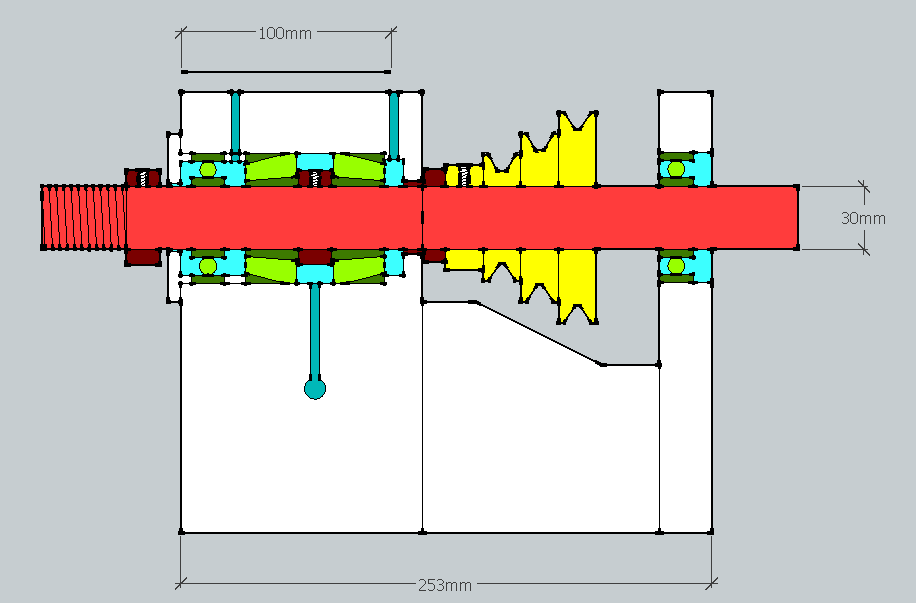
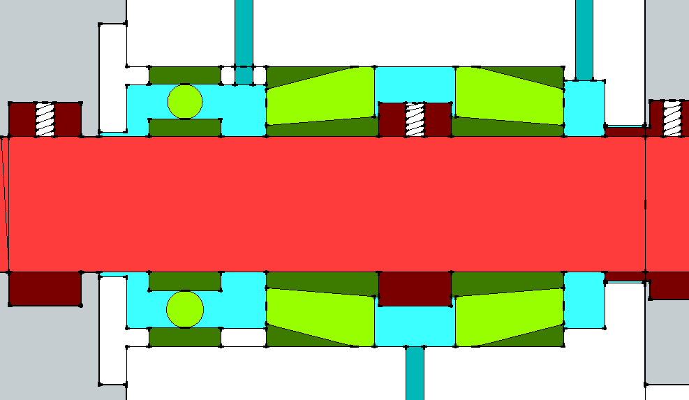
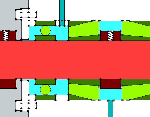
Red is 30mm bar, dark red is shaft collars, green is bearings, yellow is pulley, white is solid housing cross section and blues are hollow parts of the housing. In the front (left) bearing housing there is a deep groove ball bearing and twinned taper roller bearings. The two dark blue lines on the top are oil holes and the one below is the oil drain. According to Timken taper roller bearings naturally pump oil through themselves as they rotate so the oil should naturally splash about inside and be directed into the centre to drain off.
My question is: Is it possible and/or necesarry to seal off the points where the spindle leaves the bearing housing? I don't want oil splashing out and I don't want dirt floating in. I was thinking of getting a shaft collar, turning a small part down to 1 mm under the size of the housing opening and screwing it in place which would stop large swarf getting in but that still aloows some oil and grit to move about. |
| John McNamara | 06/05/2016 01:03:03 |
 1377 forum posts 133 photos | Hi Rainbows You really do need to keep the swarf out there are dozens of inexpensive mechanical seals available. Regards
|
| John Reese | 06/05/2016 05:22:13 |
 1071 forum posts | Posted by John McNamara on 06/05/2016 01:03:03:
Hi Rainbows You really do need to keep the swarf out there are dozens of inexpensive mechanical seals available. Regards Rainbows, I agree with John M. You need seals. You also need a shoulder against the bearing race. You also need a shoulder for the chuck to butt against. I would like to suggest some changes to make the headstock more robust. Eliminate the ball bearing on the left side of the headstock. It adds little support compared to the tapered roller bearings. Replace the two roller bearings with a single bearing of double row design. Place it as close to the left end of the headstock as possible, leaving room for a seal. That will place the bearings as close as possible to the chuck for maximum rigidity. Use shims under the bearing retainer to adjust preload. Timken and SKF have several sizes of roller bearings to fit a given shaft. That will give a choice of load capacity. The ball bearing at the right can be a pre-lubricated bearing with seals. Refer to the bearing manufacturers' literature for the proper fits on the shaft and housing. I hope this is helpful. John R
|
| John Reese | 06/05/2016 05:37:38 |
1071 forum posts | I forgot something in my earlier post. You need a locking device to prevent the spindle from pulling out when you cut toward the tailstock. I suggest using a sleeve over the spindle. One section of sleeve between the bearing and the pulley. Another sleeve between the pulley and the outboard bearing and a locknut against the outboard side of the ball bearing. I suggest this approach so it is not necessary to reduce the spindle diameter in order to install a locknut against the roller bearings. It also provides positive location for the ball bearing. |
| Raymond Anderson | 06/05/2016 07:11:59 |
 785 forum posts 152 photos | Your best option would be a "Labyrinth " seal, various types designed for lathe / milling spindles. Some designs involve fairly complex machining, other styles less so. Cheers. |
| Rainbows | 06/05/2016 07:52:52 |
| 658 forum posts 236 photos | Quick morning reply:
I agree on the right being a lubricated for life bearing. Re haveing no steps on the shaft: The plan was to have the shaft collars act as the chuck abutment face and to bear on the taper roller bearings. Doing this instead of turning the steps from a larger piece of stock is that at the moment I have no lathe that is big and accurate (I have one thats small and access to one with tapers and runout all over the place). Would using shaft collars be suitable for this?
One thing I didn't explain properly in the original.
The plate on the left is bolted into the housing. The design will probably need changing to accomodate a seal but the idea is the tighter the bolts are the more it is pulled in, pushing the ball bearing further in then though a small ring between the ball bearing and taper bearing preload the taper roller bearings and keeping everything positioned. Will have a look through more of those alternate designs and look around for seals later today.
|
| JasonB | 06/05/2016 08:11:05 |
 25215 forum posts 3105 photos 1 articles | I'd get the taper bearings further apart, being so close together and in the middle of teh shaft you will not get the benifit of the taper and will still have the slight ply from the end bearing where you need the support. Out of interest all my lathe has is a close fitting 3mm thick disc between bearing and the outside world, seems to work OK. |
| John McNamara | 06/05/2016 08:24:09 |
1377 forum posts 133 photos | Hi Rainbows The problem with a separate shaft collar is getting it sit perfectly on the shaft, even with a press fit there is a chance it will be slightly canted, if it is there will be a cam action forcing the spindle to move in and out as it rotates. It behaves like a micro version of a swash plate, often used in car aircon compressors. The same laws apply to the nut and lock nut used to set the preload on the bearings against the shoulder, for better quality machines sometimes these nuts are turned or more likely ground while mounted on the spindle as a set. Maybe you can find a local model engineer with a larger lathe to make the spindle. Regards |
| Neil Wyatt | 06/05/2016 09:44:33 |
 19226 forum posts 749 photos 86 articles | There are old but excellent designs for taper bearing spindles from Timken here: www.model-engineer.co.uk/news/article/lathe-bearings/19136 Your design is a bit like number 2, but I think you should give more consideration top getting support closer to the ends of the spindle. Neil Edited By Neil Wyatt on 06/05/2016 09:45:54 |
| Ady1 | 06/05/2016 10:02:11 |
 6137 forum posts 893 photos | Your best bet IMO is to study what various lathe companies did over the last 100 years and then apply yourself to the task Personally speaking, I'm a solid bearings fan |
| Rainbows | 06/05/2016 10:02:17 |
| 658 forum posts 236 photos |
This is where I got the idea for that ball bearing. I assume SKF had their reasons so I blindly followed it even though I wasn't sure what the extra cylindrical roller bearing was doing there. That timken article is a great link though.
Am I correct to say that if I bought this then it would be a matter of locating it in the 62mm bore and it would keep debri out and oil in? Edited By Rainbows on 06/05/2016 10:08:06 |
| Raymond Anderson | 06/05/2016 10:33:23 |
785 forum posts 152 photos | Hi Rainbows, The way I see it is since you are designing the lathe from the ground up then you have the opportunity to adopt "best practice" and utilise a proper seal for the bearings / spindle. I take me hat off to you for taking this on as it is no small task. It will involve considerable work ,and possibly expense [that depends on final spindle size ,Bearings ect] so best do it right. from the start. Labyrinth seals are designed for just that application A good place with all the info you could need re bearings for machine tools is www.shaeffler.com there you can view or download a pdf . Remember also the bigger the spindle Ø the bigger the bore you can have, the down side is bigger bearings and more cost. It will certainly be a "challenge " so best get things right. Good luck. |
| Raymond Anderson | 06/05/2016 10:36:43 |
785 forum posts 152 photos | Also as a aside, It need not be the super complex type of Labyrinth seal, there are a multitude of types from complex to less so. Many bearing manufactures make them, as do others that only specialise seals. |
| mgnbuk | 06/05/2016 11:52:51 |
| 1394 forum posts 103 photos | This is where I got the idea for that ball bearing Those roller bearings "NN" have a very shallow taper to the inner race bore - they fit to a mating taper on the spindle and, when sufficient force is applied by the locknut, the inner race expands to take out the radial play. The oil port that comes out at the front of the spindle nose leads to a groove - high pressure hydraulic oil (think 10,000 psi + ) is injected here to help get the inner race off at rebuild time . This arrangement is favored by several German builders of heavy duty lathes - sometimes the pre-loaded double angular contact thrust bearing is replaced with standard ball thrust bearings. Very, very expensive in precision grades & can be very hard to find. Note the labyrinth seal at the spindle nose, with drain hole at the bottom to let coolant out. As a solution, this is way overkill for a small lathe IMO - opposing taper roller bearings at each end of the spindle as used by Boxford (for example) would be fine. If you cannot turn a spindle with a suitable integral location flange, could you design your headstock around one of the mini-lathe spindles, which appear to be quite cheap as spare parts ? Nigel B |
| John Stevenson | 06/05/2016 11:59:43 |
 5068 forum posts 3 photos | You have got your taper roller bearings in arse about. |
| Hopper | 06/05/2016 12:23:33 |
 7881 forum posts 397 photos | Posted by John Stevenson on 06/05/2016 11:59:43:
You have got your taper roller bearings in arse about. Harley Sportsters of the 1970s-80s used two taper roller "earse about" like that for the swingarm pivot. But it would not be the first time the fine engineers from Milwaukee did something erse about! |
| Hopper | 06/05/2016 12:36:21 |
7881 forum posts 397 photos | I'd be tempted to make life easy for myself if I were doing this job by using a pair of readily available tapered roller bearings used as car wheel bearings. The kits, some with seals included, are available at car parts stores etc. Just set them up like in a car, with the bearings opposed (but not erse about as Mr Stevenson points out). Standard rubber lip seal on each end should keep swarf out and oil in. Put a step or collar on the chuck end of the spindle and a thread and nut on t'other so you can tighten up for a little bit of preload. Outer races of the bearings would need to be held firm by steps in the bores they fit into, flat plates bolted on the ends as already proposed, or by circlips in grooves machined into the bores. Plenty of commercial lathes use this set up quite successfully. EG Boxford etc. Viz:
Good idea pointed out above to look into using a pre-made spindle sold as spare parts for cheapo Chinese lathes (or others). If you make your own, using your idea of the collar to do away with turning down a larger shaft on a small lathe, I would use more than just a grub screw to locate it. Probably several screws or even dowel pins locating into holes in the spindle. I wouldnt worry too much about a collar sitting not quite square. If the bearing inner race is a neat fit on the spindle, it is going to run true enough. Or you could mount the collar on the spindle then spin it in your smaller lathe, presuming it fits, and take a trueing cut over the face that rests agains the bearing inner race. Edited By Hopper on 06/05/2016 12:48:38 |
| Neil Wyatt | 06/05/2016 12:50:40 |
19226 forum posts 749 photos 86 articles | Posted by Rainbows on 06/05/2016 10:02:17:
This is where I got the idea for that ball bearing. I assume SKF had their reasons so I blindly followed it even though I wasn't sure what the extra cylindrical roller bearing was doing there. That timken article is a great link though. SKF have used opposed angular contact ball bearings for end thrust and plain rollers for side thrust. The plain ball you have will only deal with side thrust, but where it is is a better place to put a roller bearing (taper or standard) - as close to the point of application of side thrust as possible. Back to back bearings to take end thrust are good - as this minimises thermal expansion between them, but is probably not a big issue for your lathe. Taper rollers at each end would be good. If using two opposed bearings to set the axial postion, the other bearings must be allowed to 'float' along the shaft. The timken designs are great, although these days most people would use fit and forget grease in the bearings of a hobby lathe, not a pumped oil supply - saves on making those labyrinth seals as well! |
| mgnbuk | 06/05/2016 13:32:03 |
| 1394 forum posts 103 photos | The timken designs are great, although these days most people would use fit and forget grease in the bearings of a hobby lathe, not a pumped oil supply - saves on making those labyrinth seals as well! Not just hobby lathes on the "greased for life" spindle bearings these days - we had a Gildemeister CTX400 slant bed CNC lathe at work that had a spindle bearing arrangement similar to the SKF drawing above that was greased for life. Why would it be a chore to make suitable labyrinth seals ? Not a difficult turning job & most do double duty as bearing retainers as well. Big plus with labyrinths over rubber seals is the lack of both drag & wear - a grease lubed rubber shaft seal will get hot & increase drag until it wears (and/or cuts a groove in the spindle), at which point it is no more than a labyrinth seal anyway. And some sort of seal is desirable to prevent coolant & swarf contamination of the bearing lubricant - grease or oil. Nigel B |
| Nick_G | 06/05/2016 13:34:25 |
 1808 forum posts 744 photos | . As it happens only this week I have replaced my taper headstock bearings in an STS 10-20 Boxford. If you would like the old ones sending to you so that you can have a play with them you are welcome to them. I realise that they are useless for your final version. But they may be of use to you to get the feel of sizes and how similar could be used in your application.
Nick |


Please login to post a reply.
Magazine Locator
Want the latest issue of Model Engineer or Model Engineers' Workshop? Use our magazine locator links to find your nearest stockist!
Sign up to our Newsletter
Sign up to our newsletter and get a free digital issue.
You can unsubscribe at anytime. View our privacy policy at www.mortons.co.uk/privacy
Latest Forum Posts
- *Oct 2023: FORUM MIGRATION TIMELINE*
05/10/2023 07:57:11 - Making ER11 collet chuck
05/10/2023 07:56:24 - What did you do today? 2023
05/10/2023 07:25:01 - Orrery
05/10/2023 06:00:41 - Wera hand-tools
05/10/2023 05:47:07 - New member
05/10/2023 04:40:11 - Problems with external pot on at1 vfd
05/10/2023 00:06:32 - Drain plug
04/10/2023 23:36:17 - digi phase converter for 10 machines.....
04/10/2023 23:13:48 - Winter Storage Of Locomotives
04/10/2023 21:02:11 - More Latest Posts...
- View All Topics
Support Our Partners


Shopping Partners
Subscription Offer

Latest "For Sale" Ads
- Reeves** - Rebuilt Royal Scot by Martin Evans
by John Broughton
£300.00 - BRITANNIA 5" GAUGE James Perrier
by Jon Seabright 1
£2,500.00 - Drill Grinder - for restoration
by Nigel Graham 2
£0.00 - WARCO WM18 MILLING MACHINE
by Alex Chudley
£1,200.00 - MYFORD SUPER 7 LATHE
by Alex Chudley
£2,000.00 - More "For Sale" Ads...
Latest "Wanted" Ads
- D1-3 backplate
by Michael Horley
Price Not Specified - fixed steady for a Colchester bantam mark1 800
by George Jervis
Price Not Specified - lbsc pansy
by JACK SIDEBOTHAM
Price Not Specified - Pratt Burnerd multifit chuck key.
by Tim Riome
Price Not Specified - BANDSAW BLADE WELDER
by HUGH
Price Not Specified - More "Wanted" Ads...
Get In Touch!
Do you want to contact the Model Engineer and Model Engineers' Workshop team?
You can contact us by phone, mail or email about the magazines including becoming a contributor, submitting reader's letters or making queries about articles. You can also get in touch about this website, advertising or other general issues.
Click THIS LINK for full contact details.
For subscription issues please see THIS LINK.
Digital Back Issues


Donate

 Register
 Log-in
Model Engineer Magazine
- Percival Marshall
- M.E. History
- LittleLEC
- M.E. Clock

ME Workshop
- An Adcock
- & Shipley
- Horizontal
- Mill

Subscribe Now
- Great savings
- Delivered to your door

Pre-order your copy!
- Delivered to your doorstep!
- Free UK delivery!
All Forum Topics > General Questions > How to seal a lathe headstock