Forum sponsored by:

Reprofiling revolving centre
| mick H | 29/10/2015 09:00:54 |
| 795 forum posts 34 photos | Can anyone please tell me the best way to reprofile the tip of a revolving centre which has had a hard life? Mick |
| Involute Curve | 29/10/2015 09:18:53 |
 337 forum posts 107 photos | I have done this with a tool post Grinder in the past, I bet it could be done with a dremel or similar also held in the tool post.
Shaun |
| David Clark 1 | 29/10/2015 09:19:25 |
 3357 forum posts 112 photos 10 articles | Lock the centre and regrind it in the headstock. |
| KWIL | 29/10/2015 11:08:05 |
| 3681 forum posts 70 photos | How do you lock a revolving centre? |
| Ian P | 29/10/2015 11:24:20 |
 2747 forum posts 123 photos | Posted by KWIL on 29/10/2015 11:08:05:
How do you lock a revolving centre? For grinding, the forces should be quite low so an optimally sized lump of weld will do it easily, more practical though might be masking tape. Piling up thin thread soaked in something sticky where the revolving part meets the stationary bit should do the job too (and keep grinding dust out) Ian P |
| ega | 29/10/2015 11:28:27 |
| 2805 forum posts 219 photos | I can suggest two possibilities: My GMT brand revolving centre point has a major diameter the same as the body and it might be possible to lock the two elements together with some form of clamp or perhaps a winding of tape. My "best" RC is a Gepy which has an oil hole closed by a small screw and I wondered whether temporarily substituting a setscrew would do the trick; this was the method adopted by Lawrence Sparey in the design for a shop-made item in "The Amateur's Lathe". Does anyone know how the makers do this? |
| John McNamara | 29/10/2015 11:30:05 |
 1377 forum posts 133 photos | Hi Mick H If you have some sort of slow speed geared or variable speed motor, a tool post grinder and a pulley and belt of some sort, First mount the revolving centre in the tailstock. Then run belt around the flat on the revolving centre to the geared or variable speed motor and turn it at around 50 to 100 rpm. you will need to do some sort of lash up to hold the motor in position and put tension on the belt. the motor does not have to be very powerful if you grind lightly. You can then grind the centre running in its own bearings with the tool post grinder. The centre should turn in the opposite direction to the tool post grinder wheel. Once I had to do this with a centre that did not have a flat. I used a rubber wheel directly mounted on the motor to turn the live centre. Regards |
| wheeltapper | 29/10/2015 15:30:30 |
 424 forum posts 98 photos | Posted by John McNamara on 29/10/2015 11:30:05:
Hi Mick H If you have some sort of slow speed geared or variable speed motor, a tool post grinder and a pulley and belt of some sort, First mount the revolving centre in the tailstock. Then run belt around the flat on the revolving centre to the geared or variable speed motor and turn it at around 50 to 100 rpm. you will need to do some sort of lash up to hold the motor in position and put tension on the belt. the motor does not have to be very powerful if you grind lightly. You can then grind the centre running in its own bearings with the tool post grinder. The centre should turn in the opposite direction to the tool post grinder wheel. Once I had to do this with a centre that did not have a flat. I used a rubber wheel directly mounted on the motor to turn the live centre. Regards
surely the centre and grinding wheel should revolve in the same direction. if they revolve in opposite directions they will behave like two gears and have hardly any opposing surface speed where as in the same direction they will have maximum opposing surface speed.
Roy. |
| Involute Curve | 29/10/2015 15:40:33 |
337 forum posts 107 photos | All I did was use the tool post grinder, the friction of the grinding wheel span the revolving part of the centre quite slowly leaving a very good finish. Shaun |
| Mike Poole | 29/10/2015 17:45:07 |
 3676 forum posts 82 photos | I have never tried it, but would araldite hold for a light grind? Maybe a small section O ring to keep the bearing joint clear. Mike |
| mick H | 29/10/2015 20:10:44 |
| 795 forum posts 34 photos | Thanks for the ideas gents. I will have a go at it and post the outcome. Mick |
| paul rayner | 29/10/2015 20:39:17 |
| 187 forum posts 46 photos | have a look on you tube, john who goes under the name of twastard engineering has done a video of one which includes stripping it down. if you do a search it may be on one of his Sunday night night caps regards Paul |
| Chris Richards 3 | 29/10/2015 20:49:52 |
| 68 forum posts 13 photos | I managed to clamp a drill upside down against the tool post on a lathe it actually worked fine as a tool post grinder |
| John McNamara | 29/10/2015 22:31:55 |
1377 forum posts 133 photos | Yes Wheeltapper I should have said same direction. The relative rotations should oppose each other where they touch. Regards |
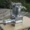
| mick H | 31/10/2015 14:44:37 |
| 795 forum posts 34 photos | I had a go at it yesterday and achieved (by my standards) a half reasonable result using a carbide tool and the set up in the picture. Unfortunately I lost about 1/4" of the tip which crumbled away....probably due to inaccurate centreing of the tool. I any event, it is in better shape than it was! |


Please login to post a reply.
Magazine Locator
Want the latest issue of Model Engineer or Model Engineers' Workshop? Use our magazine locator links to find your nearest stockist!
Sign up to our Newsletter
Sign up to our newsletter and get a free digital issue.
You can unsubscribe at anytime. View our privacy policy at www.mortons.co.uk/privacy
Latest Forum Posts
- hemingway ball turner
04/07/2025 14:40:26 - *Oct 2023: FORUM MIGRATION TIMELINE*
05/10/2023 07:57:11 - Making ER11 collet chuck
05/10/2023 07:56:24 - What did you do today? 2023
05/10/2023 07:25:01 - Orrery
05/10/2023 06:00:41 - Wera hand-tools
05/10/2023 05:47:07 - New member
05/10/2023 04:40:11 - Problems with external pot on at1 vfd
05/10/2023 00:06:32 - Drain plug
04/10/2023 23:36:17 - digi phase converter for 10 machines.....
04/10/2023 23:13:48 - More Latest Posts...
- View All Topics
Support Our Partners


Shopping Partners
Subscription Offer

Latest "For Sale" Ads
- Reeves** - Rebuilt Royal Scot by Martin Evans
by John Broughton
£300.00 - BRITANNIA 5" GAUGE James Perrier
by Jon Seabright 1
£2,500.00 - Drill Grinder - for restoration
by Nigel Graham 2
£0.00 - WARCO WM18 MILLING MACHINE
by Alex Chudley
£1,200.00 - MYFORD SUPER 7 LATHE
by Alex Chudley
£2,000.00 - More "For Sale" Ads...
Latest "Wanted" Ads
- D1-3 backplate
by Michael Horley
Price Not Specified - fixed steady for a Colchester bantam mark1 800
by George Jervis
Price Not Specified - lbsc pansy
by JACK SIDEBOTHAM
Price Not Specified - Pratt Burnerd multifit chuck key.
by Tim Riome
Price Not Specified - BANDSAW BLADE WELDER
by HUGH
Price Not Specified - More "Wanted" Ads...
Get In Touch!
Do you want to contact the Model Engineer and Model Engineers' Workshop team?
You can contact us by phone, mail or email about the magazines including becoming a contributor, submitting reader's letters or making queries about articles. You can also get in touch about this website, advertising or other general issues.
Click THIS LINK for full contact details.
For subscription issues please see THIS LINK.
Digital Back Issues


Donate

 Register
 Log-in
Model Engineer Magazine
- Percival Marshall
- M.E. History
- LittleLEC
- M.E. Clock

ME Workshop
- An Adcock
- & Shipley
- Horizontal
- Mill

Subscribe Now
- Great savings
- Delivered to your door

Pre-order your copy!
- Delivered to your doorstep!
- Free UK delivery!
All Forum Topics > Help and Assistance! (Offered or Wanted) > Reprofiling revolving centre