Forum sponsored by:

Building the 'Potty mill engine' the beginners way.
| Gas_mantle. | 27/08/2015 17:31:04 |
 359 forum posts 269 photos | Hi all, For the last few weeks I've been looking for a fairly simple steam engine to build, after much searching online and some helpful advice from a few members here I was directed towards the 'Potty mill' engine. The engine was designed to be built without the need for a mill so it suits the tooling I have at present and I decided to give it a go. At the moment the plans I have aren't in Jpeg form so I'm having difficulty uploading them here but one I've figured how to do it I'll upload for the benefit of anyone following the thread. For now here's a picture of this rather attractive little horizontal engine and hopefully mine will at least look similar when completed.
I've got a better drill vice and a few other materials on order so for a few days I'm a bit limited in the parts I can build but I've decided to make a start on those that I can do for now. I'd like this thread to be useful to beginners like myself and would be grateful if more experienced members can post their comments, ideas, suggestions, criticisms etc in the hope I can learn something as well as other beginners following. Anyway enough of that lets make a start ;- I decided the con rod looked achievable with the resources I have and began with a piece of 1/4 " thick steel plate which ultimately needs the centre turned to a fishbelly shape, a foot at one end and bearing fixture to attach to the cross head on the other end.
I decided I turn between centres so centre drilled either end and having read someone elses novel way of not needing to change to a face plate I though I'd do the same. The idea involved making a small temporary centre to sit inside the chuck and hopefully use the jaws to drive the work.
What seemed like a good idea might have worked with larger diameter stock but with the small piece I used my workpiece wouldn't fit past the jaws !
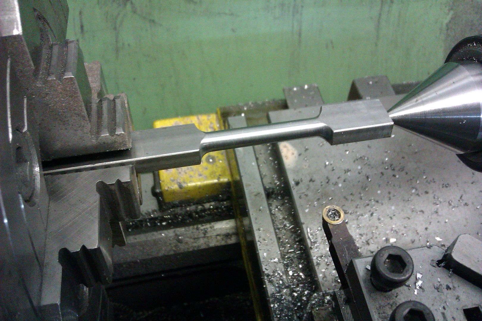
In the end I decided to use the face plate and dog and after what seemed like an eternity the piece was starting to take its rough shape.
The left hand end will become the crosshead end and needs drilling out to 8mm. There are 2 punch marks as I had originally done the righthand one for drilling purposes but decided it was slightly off the centreline so decided to redo it and use the other end. It may look in the photo that the righthand mark is more central but the lefthand one is far better. As the next photo shows the 8mm hole looks to be accurately centred and overall I'm pleased with it. Of course I've now got the rogue first punch mark to get rid off but the ends of the rod are yet to be tapered so I think with a bit of luck and some gentle filing I lose it. The 2 small cuts in the main bearing end show where the 3mm deep foot will finish.
The plans show a 6mm dia central area in the rod tapering down at 8* in either direction to give a fishbelly shape. After about an hour of trying to align the compound slide, readjust the tool post etc I found no matter how I set up I couldn't postion things so I didn't foul either the driving dog at one end or the tailstock at the other. In the end I decided that for a 50mm long rod where the taper is purely cosmetic I'd be quicker doing it with a file.
It can be seen here that it's not yet even at either end but there's more to come off yet and I'm hopeful that with another bash at it tomorrow it will be far more attractive when finished.
So this is what I have so far, despite a few glitches I'm reasonably happy. After finishing the taper all that remains is to hand file the circular cross head end, reduce to the foot depth to 3mm and give it a bit of tidying up
Edited By Peter Nichols on 27/08/2015 17:32:24 Edited By Peter N |
| mechman48 | 27/08/2015 17:42:04 |
 2947 forum posts 468 photos | Hi Pete Nice follow up model to be getting on with; looked in your album at your first model, nice job. How did you make your profiled base, did you do the woodwork with a router or bought in pre-machined strips?. Keep the pics coming. George |
| Gas_mantle. | 27/08/2015 17:47:18 |
359 forum posts 269 photos | Thanks George, The plinth the first engine was mounted on was one I bought, I think it only cost me about £10, if you wanted details of where I bought it send me a priv message and I'll give you the details. Peter. |
| Gas_mantle. | 27/08/2015 18:16:35 |
359 forum posts 269 photos | Hi, another member has kindly reproduced the con rod plan for me in JPEG form. Here is what I'm trying to make :-
Peter.
|
| JasonB | 27/08/2015 18:40:59 |
 25215 forum posts 3105 photos 1 articles | Good to see you making a start on this one Peter As one who advocates the soft centre in the chuck I thought a couple of puctures may help yopu and any others thinking of giving it a try. I like to have a small step on by soft centre so it cannot get pushed back into the chuck. The idea is to have it sticking out beyond the chuck jaws so you can take a trueing cut and then don't remove it from the chuck until the job is done, this will give you a very accurately positioned centre with no runout due to the chuck being a bit off.
You really need a cranked dog or a large straight one can be cross drilled for a bolt that will engage against the chuck jaw.
Also when marking out you should really have two punches, a dot punch and a centre punch. The dot punch is used first VERY LIGHTLY to make a small dimple, you can then inspect that and if it is not quite right the punch can be tilted slightly and tapped again which should shift the dimple to where it is required, this should still be done very lightly. Once you have the dimple where you want it that is the time to put the centre punch into teh dimple and give it a heavier blow for your drill to seat into. Dot on left, centre on right
Finally if atall possible keep the piece of work on the end of the bar as for a slong as possible so you have a bit more to hold
J |
| GarryC | 27/08/2015 18:41:36 |
 740 forum posts 1043 photos | Hi Peter Great to see you've made a start - it's going to be a great project to follow I bought an 'extended nose' type live centre and found it gave much more room... Look forward to the next update.. Cheers Garry
|
| Gas_mantle. | 27/08/2015 19:03:58 |
359 forum posts 269 photos | Thanks for the help guys. As for the punches I didn't realise there was such a thing as a dot punch, I'll be ordering one tomorrow ! When I got my bench drill a couple of weeks ago I had a practice doing punch marks and trying to accurately drill random holes, I found it very difficult to be consistently accurate but put it down to my inexperience. I only have one punch and it now seems it's far from ideal.
As you can imagine getting an accurate centre with that is virtually impossible. In making the con rod I chose the 2nd punch mark as the most accurate but even then had to gently 'persuade' the drill bit to drill very slightly off my mark. Luckily it turned out ok but I really need to be getting some better punches now I understand the problem better. Peter. |
| mechman48 | 27/08/2015 19:15:31 |
2947 forum posts 468 photos | Pete Make some punches from broken taps... or silver steel... grind to shape, heat to cherry red, quench, clean-up, gently heat lower down from the point & watch for colour climbing up to point, you should be aiming for mid to light straw colour, quench again, should give you a decent hardened point, ... or even touch up a broken centre drill, we all have one or two of those kicking about in the ' broken box' ... no need to buy stuff when you can make it ... George. |
| Alex Collins | 27/08/2015 19:42:27 |
 147 forum posts 38 photos | Hi Peter
|
| ChrisH | 27/08/2015 19:47:49 |
| 1023 forum posts 30 photos | Peter, When grinding dot or centre punches, don't grind the 'slope' across the grind wheel, grind with the point up and the slope aligned with the wheel so the grinding marks radiate down from the point. Not only will it be more pretty, but the slope should be very regular and, I was told years ago, makes the point stronger too. Don't know if that is true but sounds good. It's also a much easier way to grind the point. Chris |
| Neil Wyatt | 27/08/2015 20:24:58 |
 19226 forum posts 749 photos 86 articles | A great idea for a build thread, Peter. Here's how I approached a similar con rod - I did all the turning at this setting. The hardest bit was making sure the thickness of the rod was centralised in the four-jaw. Neil
|
| Gas_mantle. | 27/08/2015 20:37:18 |
359 forum posts 269 photos | Thanks for the replies I think with hindsight I ought to have used a piece as suggested, I think I'll get the result I want but I'm not going about it the easiest way. The only plus side to it all is when I drill the foot holes and cut the waste off I should have a piece with perfectly matching radiused sides and bolt holes to fit at the bottom end and enclose the brass bearing. |
| Gas_mantle. | 28/08/2015 19:25:32 |
359 forum posts 269 photos | Hi, Distractions and other things to do meant I didn't get as much done today as I would have liked, although I have now pretty much finished the con rod. I worked a bit more on the fishbelly taper and whilst it's not perfect it is looking better so I set about rounding off the little end bearing. I thought to try and help get an even circular profile by hand filing a template would help.
Not pretty, but functional . After much filing I made the small brass bearing insert - it's such a good fit I haven't got a chance of removing it ! I'm not sure whether that's a good thing or not ?
The belly taper could still do with a bit more taking of the little end and it does still need a bit of tidying up but overall I'm pleased with how it's looking. I've decided to leave the foot as it is for now till my drill vice arrives but otherwise it's about finished. Peter. Edited By Peter Nichols on 28/08/2015 19:26:32 |
| Gas_mantle. | 05/09/2015 11:19:29 |
359 forum posts 269 photos | Hi all, Well, my drill vice and grinder have now arrived along with a decent set of punches as suggested earlier so I'm hopefully in a position now to continue with this little engine. I decided I'd have a go at making the cylinder block. This basically consists of an aluminium rod turned and faced to size and accommodating a 16mm bore along with the steam ports and fixing holes located on 2 flat faces 90* apart. First things first, I turned the aluminium to it's final 32mm OD and faced off one end. Although a simple operation I was well pleased as the tool I used (visible in the pic) was the first home made one I've used on my new grinder and after only a few minutes making it was pleased to see it does a pretty good job for a first effort..
The bore needs to be 16mm so I need to drill it out up to my maximum drill size (13mm) and bore out the remainder.
I did have a go at making a boring bar of my own but it turned out to be a bit too big for this task so rather than maker a smaller one I decided to try the 8mm shank carbide tipped one I already have. This tool probably hasn't got the necessary reach for the depth I need but I found a brazed tipped bar I forgot I had. All I needed was for the first bar to open out the bore large enough for the 2nd (larger) bar to do the final finishing. The maker states the tipped bar will fit a 10.5 mm hole - I've no doubt there claim is true but it would take someone far more skilled than me to do it. This photo is against the 13mm hole and there isn't a great deal of clearance.
This is the bar I forgot I had - it came free with my machine as part of a set of 5 tools, I couldn't get on the with the other tools so never really used this. But needs must, my 8mm bar isn't up to the job but has at least opened up the bore large enough to give this a try.
Pleasantly surprised I found it did a decent job.
Just need to part off now.
The cylinder will ultimately sit on a base of aluminium square stock so I now need to machine a flat face parallel to the bore. I don't have a mill (this engine is specifically designed for people without access to a mill) so I'll cut the face by facing off crosswise in the lathe chuck. The valve chest will be made from a similar piece of aluminium square so I actually need to machine 2 faces at 90* to each other.
Making a guest appearance is my homemade tool post dial indicator support. I figured that for smooth running having the machined faces parallel to the bore was important so spent quite some time getting this as accurate as I could.
So far so good, the first cut seems to suggest it's parallel. The finish isn't great in this image but closer to my target dimension I took smaller cuts at higher speed to greatly improve things.
Hardly rocket science I know, but I'm reasonably pleased with it so far.
Next job, machine the other flat face, I haven't decided yet whether to drill the fixture mounting holes now or after I've machined the parts they are to secure. Thanks Peter. Edited By Peter Nichols on 05/09/2015 11:25:02 |
| Gas_mantle. | 06/09/2015 08:30:30 |
359 forum posts 269 photos | Hi, I managed to get a bit further yesterday by facing off the second face off the cylinder block and drilling the steam ports as well as drilling the base mounting block. The procedure was the same as the first face but with the added constraint of ensuring it was at 90* to the first one, I wasn't sure how best to go about this but came up with this rather makeshift idea. The first machined face can be seen upwards in the chuck, what looks like a set square is actually a packing piece at the front and one of my parallels firmly pressed against the machined face - by reading the height of the parallel over its length I was able hopefully get the second face at 90* to the first.
Success - it worked.
Next job was the simple task of drilling 2 holes 30mm apart in the mounting block, I decided to do the block before the cylinder as I might use it as a template to correctly position the corresponding holes in the cylinder. I've only had this drill a fortnight and this is the first 'proper' job I've used it for so I thought a few basic checks on it's alignment etc wouldn't go amiss.
A simple job but now I have a decent drill and a vice it's so much easier. The next task is a tad more tricky - it involves drilling in from either end to a depth of 18mm then drilling 2 shallow holes in the face to (hopefully) meet up. I've marked out and punched the centres, using a better set of punches has greatly improved my accuracy compared to the blunt pencil of a punch I was using previously.
Well here we go - the plan suggests 3mm holes but as I machined slightly more off the flat faces to fit my bar stock than the plan, the cylinder walls are a little bit thinner so I decided to try at 2.6mm first then reassess the situation.
Now a shallow 4mm inlet hole and lets hope they meet.
Well the first one meets perfectly, let's hope the second one goes to plan also.
Second one also proved to be a winner and I'm pleased with the result so far. Next job tomorrow is to cut a small passage at either end leading from the steam holes into the main cylinder bore. It can be seen in the photo how thin the cylinder walls are after going through with a 2.6mm drill - I think it's too risky to open them out to 3mm - anyone else got any thoughts ? I'd like to run this engine on live steam occasionally, is a 2.6mm steam passage going to significantly restrict the flow of steam on an engine this size compared to a 3mm hole ?
Cheers Peter. |
| Stewart Hart | 06/09/2015 08:49:52 |
 674 forum posts 357 photos | Hi Peter Nice work with the cylinder The inlet hole will be fine at 2.6mm just leave it as it is. A little tip for machining ally a squirt of WD40 does wonders for the finish:- it helps prevent build up on the cutting edge that aluminium is prone to do. When you come to drill the steam chest the position of the two inlet holes are the most important, so take your time with the marking out, line up on the position using s sticky pin (a pin held on the chuck with plastercine nudge it with a screw driver handle to get it running true and use this to line up on your marking out, clamp your vice to the table then start the drill off first with a small centre drill. The exhaust and the single air feed holes are not so critical. Cheers Stew
Cheers Stew
Edited By Stewart Hart on 06/09/2015 08:57:04 Edited By Stewart Hart on 06/09/2015 08:59:39 |
| GarryC | 06/09/2015 09:02:32 |
740 forum posts 1043 photos | Hi Peter Coming along very nicely..! Cheers Garry |
| Gas_mantle. | 06/09/2015 09:31:32 |
359 forum posts 269 photos | Hi, Thanks for the feedback Stew - I had planned on drilling the steam chest today but after reading what you've said I think I'll hold off for a day or 2 till I can get some plasticine or something similar. I think what I'll do is one of the cylinder end covers and cut the 2 passages into the main cylinder bore. Thanks Peter. |
| Dullnote | 06/09/2015 12:42:59 |
 94 forum posts 29 photos |
Hi Peter, i have just started this engine, I have the cylinder done with the support and valve chest, when drilling the cylinder to fit the rear cover, last job, I snapped the tap, after a couple of swear word, a mug of stronge coffee, managed to get the tap out, drilled down the side, made a mess of the work but should be okay to use. Hence I posted on this forum about taps. Keep up the posting, the two inlet holes, what I did was, drilling out the cylinder side, then valve side, ensured they fitted by using stubs between them this allowed me to line up the valve chest to drill the rest. Also watch the valve chest the bore is not in the centre, guess how I know. Thats right measure twice cut once, but no one says read the drawings three times.
|
| Gas_mantle. | 06/09/2015 13:00:31 |
359 forum posts 269 photos | Hi Jim, Thanks for the help, I'd be interested to hear any other comments / suggestions etc as I go along. I'm sorry to hear you broke the tap, I've just bought myself a set of 2.5mm ones as previously the smallest I had was 3mm but this engine has quite a few 2.5s. I haven't used the taps on anything yet so I'm hoping they'll work ok, depending how today goes I may be using them later. Peter. |


.jpg")
.jpg")
.jpg")
.jpg")
.jpg")
.jpg")
.jpg")
.jpg")


.jpg")
.jpg")
.jpg")
.jpg")
.jpg")
.jpg")
.jpg")
.jpg")
.jpg")
.jpg")
.jpg")
.jpg")
.jpg")
.jpg")
.jpg")
.jpg")
.jpg")
.jpg")
.jpg")
.jpg")
.jpg")
Please login to post a reply.
Magazine Locator
Want the latest issue of Model Engineer or Model Engineers' Workshop? Use our magazine locator links to find your nearest stockist!
Sign up to our Newsletter
Sign up to our newsletter and get a free digital issue.
You can unsubscribe at anytime. View our privacy policy at www.mortons.co.uk/privacy
Latest Forum Posts
- *Oct 2023: FORUM MIGRATION TIMELINE*
05/10/2023 07:57:11 - Making ER11 collet chuck
05/10/2023 07:56:24 - What did you do today? 2023
05/10/2023 07:25:01 - Orrery
05/10/2023 06:00:41 - Wera hand-tools
05/10/2023 05:47:07 - New member
05/10/2023 04:40:11 - Problems with external pot on at1 vfd
05/10/2023 00:06:32 - Drain plug
04/10/2023 23:36:17 - digi phase converter for 10 machines.....
04/10/2023 23:13:48 - Winter Storage Of Locomotives
04/10/2023 21:02:11 - More Latest Posts...
- View All Topics
Support Our Partners


Shopping Partners
Subscription Offer

Latest "For Sale" Ads
- Reeves** - Rebuilt Royal Scot by Martin Evans
by John Broughton
£300.00 - BRITANNIA 5" GAUGE James Perrier
by Jon Seabright 1
£2,500.00 - Drill Grinder - for restoration
by Nigel Graham 2
£0.00 - WARCO WM18 MILLING MACHINE
by Alex Chudley
£1,200.00 - MYFORD SUPER 7 LATHE
by Alex Chudley
£2,000.00 - More "For Sale" Ads...
Latest "Wanted" Ads
- D1-3 backplate
by Michael Horley
Price Not Specified - fixed steady for a Colchester bantam mark1 800
by George Jervis
Price Not Specified - lbsc pansy
by JACK SIDEBOTHAM
Price Not Specified - Pratt Burnerd multifit chuck key.
by Tim Riome
Price Not Specified - BANDSAW BLADE WELDER
by HUGH
Price Not Specified - More "Wanted" Ads...
Get In Touch!
Do you want to contact the Model Engineer and Model Engineers' Workshop team?
You can contact us by phone, mail or email about the magazines including becoming a contributor, submitting reader's letters or making queries about articles. You can also get in touch about this website, advertising or other general issues.
Click THIS LINK for full contact details.
For subscription issues please see THIS LINK.
Digital Back Issues


Donate

 Register
 Log-in
Model Engineer Magazine
- Percival Marshall
- M.E. History
- LittleLEC
- M.E. Clock

ME Workshop
- An Adcock
- & Shipley
- Horizontal
- Mill

Subscribe Now
- Great savings
- Delivered to your door

Pre-order your copy!
- Delivered to your doorstep!
- Free UK delivery!
All Forum Topics > Work In Progress and completed items > Building the 'Potty mill engine' the beginners way.