Forum sponsored by:

Pinning 10V Crankshaft
| Ferrum | 18/07/2015 16:29:40 |
| 23 forum posts | I have just fabricated a Stuart 10V crankshaft. The short pin and the axle were sliding fits in the web holes and cleaned with acetone. My intuition is that Loctite 638 should hold it satisfactorily. However, the plan indicates that pinning is expected. I have searched the site and found good information, particularly from Ramon Wilson, but please could someone with experience advise me on the following: (a) Is 1.6 mm mild steel (panel pin) a suitable diameter? (b) The Stuart plan shows the pins extending through the “flat side edges” of the web. Would it not be better to go through the “curved ends” of the web? (c) Do pins extend right through the diameter of the shafts into the web on the other side? (d) Do pins need an interference fit such that they have to be inserted with firm taps of a hammer or will a sliding fit with Loctite suffice?
|
| JasonB | 18/07/2015 16:49:02 |
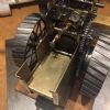
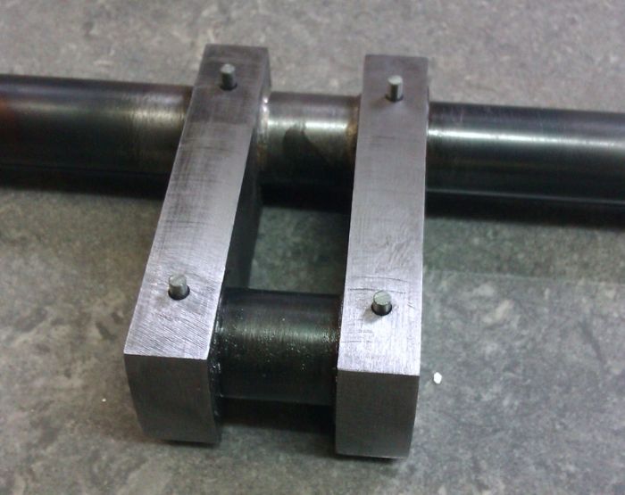
 25215 forum posts 3105 photos 1 articles | a. That would be about right, just use a drill that gives a close fit to what you have to hand b, Better to use 4 pins that go from side to side rather than two long ones end to end c, Drill the hole right through until it breaks out the other side of the web d, they don't want to be a sloppy fit but then again should not need a 2lbs lump hammer to drive them in, light push fit is what to aim for. e, leave the pinds 1/16" proud each end and then lightly pein them over with a hammer which will expand them into teh holes and eliminate slack and when filed flush should become invisible.
J Edited By JasonB on 18/07/2015 16:50:21 |
| Roderick Jenkins | 18/07/2015 17:14:44 |
 2376 forum posts 800 photos | Excellent advice there from Jason. In a spirit of enquiry, definitely not criticism since I am unsure myself: Why do we pin as well as Loctite? ( in Jason's illustration it looks silver soldered and pinned). If the "adhesive" is not strong enough to hold the joint why not just pin? I'm just having difficulties getting my head round the logic Rod |
| Neil Wyatt | 18/07/2015 17:29:06 |
 19226 forum posts 749 photos 86 articles | Perhaps we still don't trust loctite? We just love belt and braces. In my view the role of the pins is to ensure accurate alignment, and I'm sure that's why Jason pinned his. There's no need to leave a space for silver solder to flow into with loctite, so a press fit would be ideal making pinning unnecessary. "The best performance for slip fits is achieved using clearances between 0.025 mm and 0.075 mm (0.001 in. and 0.003 in.), or with interference fits. Performance is reduced as the clearance is increased." (My emphasis) www.henkelna.com/us/content_data/326508_9294_LT5021_Retaining_Brochure_FINAL.pdf Neil |
| Ferrum | 18/07/2015 17:30:17 |
| 23 forum posts | Thank you very much, Jason. Just what I needed to know with pictures as well! I must learn to silver solder as neatly as you. Rod: you have expressed what was puzzling me. Is pinning now a custom hallowed by necessary past use? Could the pin support the "glued" join from the varying load through the cycle? I do not know but I have read that Loctite 638 is very effective. Perhaps the pinning is to insure against a sub-standard joint resulting from poor Loctite technique? Thanks, again. Ron
|
| Ferrum | 18/07/2015 17:32:09 |
| 23 forum posts | Thanks, Neil. |
| JasonB | 18/07/2015 17:43:54 |
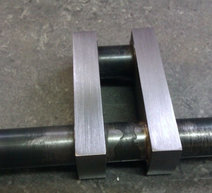
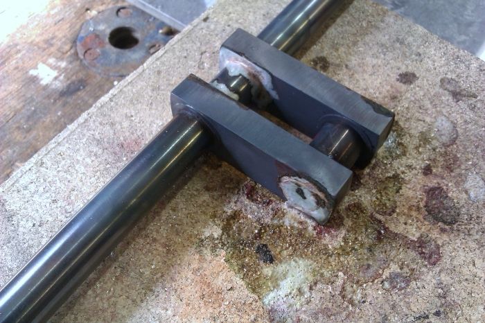
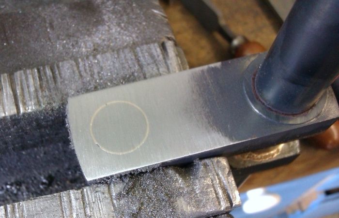
25215 forum posts 3105 photos 1 articles | Rod, I suppose it's belts and braces. I have read too many times on forums of loctited crankshafts letting go and slipping or pressed fitted ones not going together true or all the way. I generally prefer to silver solder and the pins add nothing to the alighnment Neil as they will not affect the position of an already soldered joint being drilled after soldering, they are just there incase the solder may look OK on the outside but has not penitrated the joint. You also need to bear in mind that a lot of my crankshafts are for large hit & miss engines which have quite a punch when they fire and that puts a lot more load into the joints than the relatively constant force from a steam engine. The other thing to watch with Neils 0.001-0.003" clearance is that of keeping things lined up when assembling, some of my cranks can be over 12" long and that 0.003" play in the middle could be 0.010 - 0.015" at the ends Ron, one trick when soldering up cranks is to put a light CSK on the side of the web that will be away from the shaft/pin and feed your solder in from that edge, it keeps the solder off the running surfaces so less clean up and you should be left with a neat ring of solder filling teh CSK and hopefully penitrating teh joint.
|
| Ferrum | 18/07/2015 17:57:35 |
| 23 forum posts | Wow, Jason, that is so neat! Thanks. Ron |
| Neil Wyatt | 18/07/2015 18:01:11 |
19226 forum posts 749 photos 86 articles | > The other thing to watch with Neils 0.001-0.003" clearance is that of keeping things lined up when assembling, some of my cranks can be over 12" long and that 0.003" play in the middle could be 0.010 - 0.015" at the ends I was trying to encourage the use of a press fit! |
| Brian Abbott | 30/03/2018 19:44:09 |
 523 forum posts 95 photos | Hello Jason. Did you skim the inner and outer cheeks of this crank after soldering ? Also, did you skim the con rod journal ? I have just soldered the crank for my 1" minnie, before soldering the journal was a really nice fit in the con rod, possibly still is under the solder which has collected in the joint !
|
| JasonB | 30/03/2018 20:07:07 |
25215 forum posts 3105 photos 1 articles | Inner and outer cheeks are just draw filed and if the pin or journals need cleaning up then just some work fine emery is all that I use, trick is to keep the solder off the bits where you don't want it.
|
| Brian Abbott | 30/03/2018 22:41:48 |
523 forum posts 95 photos | Thanks for the reply Jason. |
| Maurice | 30/03/2018 22:57:58 |
| 469 forum posts 50 photos | With reference to Neil's concern over keeping the parts of the crankshaft aligned when assembling with "Loctite", I use the following method. I assemble the crankpin into the webs with the adhesive, aligning the other ends of the webs with a close fitting piece of steel, and leave to cure. Meanwhile I take a pair of matching "V" blocks with clamps, place them on a flat ground surface and clamp a length of ground steel bar into both, with a space between, wide enough to take the webbs, plus about 1/4". While firmly clamped, I apply a low strength "Loctite" to the undersides of the blocks and temporarily stick them to the ground surface (my drilling machine base). When all is cured, the parts of the crankshaft can be assembled with "Loctite", placed in the "V" blocks, and clamped and again left to cure with all the parts aligned. The last one that I did this way was for a ST No. 9. When finished, I held the first inch of it in a collet and clocked the other end. The runout was four tenths of a thou. The "V" blocks can be removed from the ground surface with a sharp tap with a hammer with a piece of brass interposed. |
| mechman48 | 30/03/2018 23:20:13 |
 2947 forum posts 468 photos | IIRC I assembled my S10V with Loctite & then pinned from both sides, so ... |
| Terry Bailey 1 | 10/11/2020 19:45:32 |
| 1 forum posts | Just out of curiosity, would 1/16" taper pins with locktite be a correct way to go? |

.jpg")
Please login to post a reply.
Magazine Locator
Want the latest issue of Model Engineer or Model Engineers' Workshop? Use our magazine locator links to find your nearest stockist!
Sign up to our Newsletter
Sign up to our newsletter and get a free digital issue.
You can unsubscribe at anytime. View our privacy policy at www.mortons.co.uk/privacy
Latest Forum Posts
- *Oct 2023: FORUM MIGRATION TIMELINE*
05/10/2023 07:57:11 - Making ER11 collet chuck
05/10/2023 07:56:24 - What did you do today? 2023
05/10/2023 07:25:01 - Orrery
05/10/2023 06:00:41 - Wera hand-tools
05/10/2023 05:47:07 - New member
05/10/2023 04:40:11 - Problems with external pot on at1 vfd
05/10/2023 00:06:32 - Drain plug
04/10/2023 23:36:17 - digi phase converter for 10 machines.....
04/10/2023 23:13:48 - Winter Storage Of Locomotives
04/10/2023 21:02:11 - More Latest Posts...
- View All Topics
Support Our Partners


Shopping Partners
Subscription Offer

Latest "For Sale" Ads
- Reeves** - Rebuilt Royal Scot by Martin Evans
by John Broughton
£300.00 - BRITANNIA 5" GAUGE James Perrier
by Jon Seabright 1
£2,500.00 - Drill Grinder - for restoration
by Nigel Graham 2
£0.00 - WARCO WM18 MILLING MACHINE
by Alex Chudley
£1,200.00 - MYFORD SUPER 7 LATHE
by Alex Chudley
£2,000.00 - More "For Sale" Ads...
Latest "Wanted" Ads
- D1-3 backplate
by Michael Horley
Price Not Specified - fixed steady for a Colchester bantam mark1 800
by George Jervis
Price Not Specified - lbsc pansy
by JACK SIDEBOTHAM
Price Not Specified - Pratt Burnerd multifit chuck key.
by Tim Riome
Price Not Specified - BANDSAW BLADE WELDER
by HUGH
Price Not Specified - More "Wanted" Ads...
Get In Touch!
Do you want to contact the Model Engineer and Model Engineers' Workshop team?
You can contact us by phone, mail or email about the magazines including becoming a contributor, submitting reader's letters or making queries about articles. You can also get in touch about this website, advertising or other general issues.
Click THIS LINK for full contact details.
For subscription issues please see THIS LINK.
Digital Back Issues


Donate

 Register
 Log-in
Model Engineer Magazine
- Percival Marshall
- M.E. History
- LittleLEC
- M.E. Clock

ME Workshop
- An Adcock
- & Shipley
- Horizontal
- Mill

Subscribe Now
- Great savings
- Delivered to your door

Pre-order your copy!
- Delivered to your doorstep!
- Free UK delivery!
All Forum Topics > Beginners questions > Pinning 10V Crankshaft