Forum sponsored by:

Hep with steam chest
| Eric Cox | 07/02/2015 10:01:32 |
 557 forum posts 38 photos | I'm designing a steam chest/valve with a predetermined stroke of 20mm. How do I work out the position of the ports and the length of the slide valve. I can't get my head round it and it's driving me nuts |
| Lambton | 07/02/2015 10:26:13 |
 694 forum posts 2 photos | Eric, Can you provide a sketch, with some dimensions, of where you are so far? |
| Eric Cox | 07/02/2015 10:54:05 |
557 forum posts 38 photos | Not much to sketch, just a steam chest 44mm long and the slide having a stroke (length of travel) of 20mm |
| fizzy | 07/02/2015 12:48:26 |
 1860 forum posts 121 photos | ok this is off the top of my head...if stroke is 20mm then eccentric offset is 10mm, assuming you want to use full stroke. then divide half stroke into 4 parts, first part is exhaust, then land, then inlet then land. mark out from max stroke 2.5mm land, 2.5mm inlet, 2.5mm land, 5mm ehhaust, 2.5mm land and 2.5mm inlet. Slide walve will be 10mm id and 15mm od. That's your basic desigh. |
| Eric Cox | 07/02/2015 14:12:34 |
557 forum posts 38 photos | Thanks fizzy, just the job
|
| John Baguley | 07/02/2015 14:17:36 |
 517 forum posts 57 photos | Hi Eric, You are really designing it a**se about face as you would normally determine the port width and the lap of the valve and then determine the required valve travel. But: Total valve travel = 2 x (port width +Lap of the valve) assuming the ports fully open. (Lap of the valve is the amount the valve land is wider than the port) So if your valve travel is 20mm then your port width + valve lap will be 10mm assuming the port will fully open. Things are complicated by the fact that the ratio of the lap to the port width determines the maximum cut off of the steam to the cylinder. If you make the port width 5mm and the lap of the valve 5mm then the maximum cut off is 75% If you make the port width 7mm and the lap 3mm then the maximum cut off will be 91% Will you be using a fixed valve gear e.g. a fixed eccentric or a variable cut off valve gear such as Stephensons link? If you are using a fixed eccentric then you probably want the cut off to be 50 - 60% to avoid wasting steam. The distance between the ports doesn't affect the valve timing and is more a case of picking a suitable figure so that the valve will fit in the valve chest without hitting the ends. You will also need to fit the exhaust port inbetween the steam ports. If you're not too familiar with valve gears then this might help to explain the terms used etc.: http://www.modeng.johnbaguley.info/Valve%20Gears/Basics.htm Fizzy - your dimensions are half what they should be. Using your figures the total valve travel would only be 10mm. John Edited By John Baguley on 07/02/2015 14:24:48 |
| Neil Wyatt | 07/02/2015 14:40:26 |
 19226 forum posts 749 photos 86 articles | I wrote this six years ago (I know becauise I'm not 46 any more!), then decided others know better than me. Happy to receive criticism of it - it may be complete nonsense to anyone else... and shape it up as a proper article, Valves I designed this way have worked! Neil. Designing Simple Slide ValvesIn the dim past, Model Engineer used to have a section for queries, separate from the main letters page. Readers had to write in enclosing a small voucher printed in each issue, to receive a response from luminaries such as ETW or even Percival Marshall himself. These enquiries were often very practical, such as "where can I get castings for X?" or "how many turns are needed to rewind motor Y for 240 volts?". I think it would be a marvellous idea to recreate such a feature; I have benefited from the advice of the editorial team on a number of occasions, and I would have had no qualms about this correspondence being published. Perhaps, if other readers agree, the editors will consider this suggestion? Aside from the perennial rewinding of various electrical coils (at 46 am I one of the youngest people who remembers winding their own transformers by hand?), one of the commonest requests was for the dimensions of slide valves. I have designed a few simple slide and piston valves, all of which have worked, and it has struck me that, though their design appears complex, it can be boiled down to a few simple rules of thumb. I am not going to pretend to be in the realm of who will give you a marvellous formula for lap, lead, port sizes and steam chest volumes. I am just thinking of anyone designing a simple engine and who wants to set out sizes for a valve that will work in the space available. The example which started my chain of thought was a small table engine described in an old ME, accompanied by a small but clear two-view sketch. The full size engine had 13" stroke and 9" bore and a 4' 3" flywheel on a table 4' 6" high. From these dimensions and the sketch it was apparent that the valve chest would be about 3/8" deep and 1"long. The eccentric strap would be about 1/2" diameter. The width of the valve chest could not be calculated, but a sensible proportion would be about the same as the cylinder bore of 3/4". From the point of view of setting out the valve and eccentric there are two important dimensions: 1 Port width which should be a large as possible, to allow free passage of steam. 2 Valve travel - which is limited by the size of the valve chest and the eccentric. The two arbitrary steps which makes it easy to link, and therefore fix, these dimensions are to make the port width and spacing equal, and assume that the steam ports close and open exactly as the exhaust ports do the opposite. Now this means, for example, that the exhaust port will not be larger to allow free passage of the exhaust. For the typical model that will not be doing hard work, fine tuning is not critical, and most importantly valve gear to these specifications will work and will only need one adjustment - setting the eccentric angle. In any case, once a valve has been laid out with equal widths, it is relatively easy to make adjustments. Let us assume a port width of 'x' . A look at Figure 1 shows how all the other critical dimensions follow: Port width = x Port spacing = x Valve travel = 2x Valve length = 5x Valve cavity length = 3x Eccentric eccentricity(!) = x Less critical dimensions, which can be varied, are: Port width ~ 3x Valve width ~ 5x Valve cavity width ~ 3x Steam chest (internal) length >= 8x Steam chest (internal) width >= 6x Steam chest(internal) depth >= 4x Distance from slide valve rod centreline to valve face ~ 3x Typical diameter of slide valve rod = x |
| Neil Wyatt | 07/02/2015 14:40:41 |
19226 forum posts 749 photos 86 articles | ... continued:
The steam chest dimensions are minima sufficient to give the valve working clearance. Ideally they will be larger to increase efficiency. A wider valve is easier to produce. The depth is wholly arbitrary, but 4x gives good proportions. As we only have one variable, x, we can set it to the largest size within the limits of the size of the steam chest and eccentric. A steam chest 1" long could have a cavity approaching 3/4" long. That would make x=3/32". But this would mean eccentricity of 13/64". This is possible with a 1/2" diameter eccentric, but would need a small pin and a very thin strap! It makes sense for the eccentric to be the limiting dimension. 1/8" eccentricity would fit easily. There is enough room for us to cheat a little and make the denominator a five e.g. 5/32" everything else becomes easy: Port width = x : 1/16" Port spacing = x : 1/16" Valve travel = 2x : 1/8" Valve length = 5x : 5/16" Valve cavity length = 3x : 3/16" Eccentric eccentricity(!) = x : 1/16" In the space available, the port width can't really exceed 3/16". Port width ~ 3x : 3/16" Valve width ~ 5x : 5/16" Valve cavity width ~ 3/16" Similarly, the minimum internal length of the steam chest is 1/2", but with outside dimensions of 1" by 3/4" walls 3/16" thick will clear the sides of the valve and give a little room for error at the extremes of valve travel: Steam chest (internal) length >= 8x : 5/8" Steam chest (internal) width >= 6x : 3/8" Steam chest(internal) depth >= 4x : 1/4" Distance from slide valve rod centreline to valve face ~ 3x : 3/16" Typical diameter of slide valve rod = x : 1/16"
The only questions now are working to the required level of accuracy. The valve itself is easily made by drilling and filing a suitable cavity in a piece of 1/16" thick brass and silver soldering this to a thicker piece before cutting out the full shape of the valve. The ports can be milled out, but for guaranteed accuracy there is nothing to beat a simple ganged cutter as advocated by LBSC. Finally, all the sizes I have used in my calculations are imperial, but these equations will work just as well in metric, thousandths of an inch or even in Venusian Wibble-Ergs. What they do highlight, however, a key difference between the Imperial and Metric systems. It is very easy to design something in Imperial units. Say you want to redesign the slide valve so that the exhaust port is 50% wider than the steam ports? Add 1/32" to the exhaust port width, and all the related dimensions changes, but are still sensible Imperial dimensions. If your port was 1.6mm wide, a "preferred value", it becomes 2.2mm, which is a "third choice" value. OK you can round to a preferred value, but then all your other sizes change by unpredictable amounts. I like designing in fractional units, it is so much easier to choose reasonable proportions and keep track of how cumulative dimensions add up and change. |
| Neil Wyatt | 07/02/2015 14:43:27 |
19226 forum posts 749 photos 86 articles | I'd now add that the exhaust port can be usefully made wider, and if so the valve length and valve cavity length need to be widened by the same amount. Neil |
| John Baguley | 07/02/2015 16:02:55 |
517 forum posts 57 photos | Neil, Reading the above implies to me that you have not allowed for any lap on the valve i.e. you have made the face on the valve the same width as the port so it just covers the port? That will work (very old designs had this) but it means the cut off will be 100% i.e. the port will be open for the full stroke of the piston. Probably ok for running on air but very wasteful if running on steam as the steam won't be used expansively. John |
| fizzy | 07/02/2015 16:16:44 |
1860 forum posts 121 photos | hi JB....I would never doubt you, but it was off the top of my head!!!
|
| Neil Wyatt | 07/02/2015 17:12:59 |
19226 forum posts 749 photos 86 articles | Hi John, That's the sort of critique it needs. I think you are right - it basically follows the design for the Stuart 10V (IIRC) that has no lap. To add lap, you need to make the valve longer. To work out b y how much, I'd need to draw a reuleaux diagram.
Neil
|
| julian atkins | 07/02/2015 21:17:39 |
 1285 forum posts 353 photos | i think that eric has got you all a bit confused perhaps? what valve gear and what type of engine/loco and what size cylinders? if not a loco what is it for? 20mm even to my imperial brain sounds rather a lot of valve travel for the stuff im used to! cheers, julian |
| Nick_G | 07/02/2015 23:23:06 |
 1808 forum posts 744 photos | . Not totally relavent to the OP's question but this is quite an interesting video about steam engine valves. **LINK**
Nick |
| Eric Cox | 08/02/2015 08:38:08 |
557 forum posts 38 photos | I'm designing a twin cylinder mill engine based on a picture of the prototype I came across on t'internet. The prototype uses a crank instead of an eccentric and 20mm is the shortest stroke I can get using an 8mm crank shaft and a 6mm little end with a distance of 3mm between the two' Shaft dia/2 + 3mm + little end dia/2 = 4 + 3 + 3 = 10mm. To make matters worse the prototype doesn't use a conventional cross head but that's another story. Edited By Eric Cox on 08/02/2015 08:39:54 Edited By Eric Cox on 08/02/2015 08:40:13 |
| HomeUse | 08/02/2015 09:44:56 |
 168 forum posts 12 photos |
|
| steve de24 | 08/02/2015 16:44:15 |
| 71 forum posts | Thanks to Neil Wyatt and John Baguley for their valve timing explanations. This newcomer found them interesting reading. Steve |
| Mark Braham | 17/05/2020 11:02:15 |
| 15 forum posts | Sorry to jump in but i need help, im building my first engine (the potty mill engine) and the piston valve block shows no exhaust ports on the drawing. Is this correct ? Ive seen a few videos of them running with nothing to give me a clue unless there are drillings on the underside. Cheers Mark |
| SillyOldDuffer | 17/05/2020 11:51:37 |
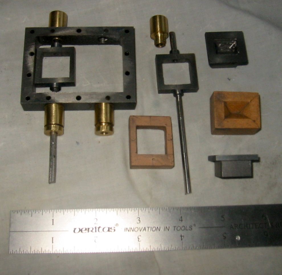
| 10668 forum posts 2415 photos | Posted by Mark Braham on 17/05/2020 11:02:15:
.., im building my first engine (the potty mill engine) and the piston valve block shows no exhaust ports on the drawing. Is this correct ... Hi Mark, Do you mean this part?
The two holes on the blue face (which is normally underneath) are the exhaust ports. The two same sized holes on the right face feed the cylinder, and the input port is invisible on the other side.
Dave |


Please login to post a reply.
Magazine Locator
Want the latest issue of Model Engineer or Model Engineers' Workshop? Use our magazine locator links to find your nearest stockist!
Sign up to our Newsletter
Sign up to our newsletter and get a free digital issue.
You can unsubscribe at anytime. View our privacy policy at www.mortons.co.uk/privacy
Latest Forum Posts
- *Oct 2023: FORUM MIGRATION TIMELINE*
05/10/2023 07:57:11 - Making ER11 collet chuck
05/10/2023 07:56:24 - What did you do today? 2023
05/10/2023 07:25:01 - Orrery
05/10/2023 06:00:41 - Wera hand-tools
05/10/2023 05:47:07 - New member
05/10/2023 04:40:11 - Problems with external pot on at1 vfd
05/10/2023 00:06:32 - Drain plug
04/10/2023 23:36:17 - digi phase converter for 10 machines.....
04/10/2023 23:13:48 - Winter Storage Of Locomotives
04/10/2023 21:02:11 - More Latest Posts...
- View All Topics
Support Our Partners


Shopping Partners
Subscription Offer

Latest "For Sale" Ads
- Reeves** - Rebuilt Royal Scot by Martin Evans
by John Broughton
£300.00 - BRITANNIA 5" GAUGE James Perrier
by Jon Seabright 1
£2,500.00 - Drill Grinder - for restoration
by Nigel Graham 2
£0.00 - WARCO WM18 MILLING MACHINE
by Alex Chudley
£1,200.00 - MYFORD SUPER 7 LATHE
by Alex Chudley
£2,000.00 - More "For Sale" Ads...
Latest "Wanted" Ads
- D1-3 backplate
by Michael Horley
Price Not Specified - fixed steady for a Colchester bantam mark1 800
by George Jervis
Price Not Specified - lbsc pansy
by JACK SIDEBOTHAM
Price Not Specified - Pratt Burnerd multifit chuck key.
by Tim Riome
Price Not Specified - BANDSAW BLADE WELDER
by HUGH
Price Not Specified - More "Wanted" Ads...
Get In Touch!
Do you want to contact the Model Engineer and Model Engineers' Workshop team?
You can contact us by phone, mail or email about the magazines including becoming a contributor, submitting reader's letters or making queries about articles. You can also get in touch about this website, advertising or other general issues.
Click THIS LINK for full contact details.
For subscription issues please see THIS LINK.
Digital Back Issues


Donate

 Register
 Log-in
Model Engineer Magazine
- Percival Marshall
- M.E. History
- LittleLEC
- M.E. Clock

ME Workshop
- An Adcock
- & Shipley
- Horizontal
- Mill

Subscribe Now
- Great savings
- Delivered to your door

Pre-order your copy!
- Delivered to your doorstep!
- Free UK delivery!
All Forum Topics > Beginners questions > Hep with steam chest