Forum sponsored by:

Restoring Beaver VBRP Mill
Documenting strip and rebuild of this English built milling machine
| Travis Hitt | 16/01/2017 14:46:06 |
| 6 forum posts 20 photos | Atlanta. Also I just realized your machine appears to have a int40 taper and I think the drawbar dimensions will be different. Mine is a r8/int30 taper with the shorter nose. I guess ill get out the tape measure and get a universal draw bar from mcmaster. |
| Robert James 3 | 18/01/2017 15:43:37 |
 18 forum posts | Can yu send me a link to the McMaster page? My draw bar is a home made rig. Thanks! |
| Travis Hitt | 28/01/2017 15:37:49 |
| 6 forum posts 20 photos | here you go man, https://www.mcmaster.com/#milling-machine-drawbars/=163xfl1
make sure they will work with your machine obviously |
| Travis Hitt | 09/02/2017 18:44:30 |
| 6 forum posts 20 photos | uploading 5 pics at a time into an album and then selecting each photo one at a time to post really sucks so these are all the pictures i was willing to load today...more to come Edited By Travis Hitt on 09/02/2017 18:46:32 |
| Tony Capstack | 27/02/2017 20:04:10 |
| 2 forum posts | Hi all, I'm new to the forum and have just purchased a Beaver VBRP. I'm currently working out how to get it off my trailer over an 8ft wall and into my home workshop. Looks to be loads of useful information in the forum and I was wondering if anyone has an electronic copy of the maintenance manual that they would be able to send me as I'm sure it needs a few jobs doing on it before I get it up and running. Any help would be much appreciated! |
| Thomas Staubo | 28/02/2017 10:39:50 |
 54 forum posts | Posted by Tony Capstack on 27/02/2017 20:04:10:
Hi all, I'm new to the forum and have just purchased a Beaver VBRP. I'm currently working out how to get it off my trailer over an 8ft wall and into my home workshop. Looks to be loads of useful information in the forum and I was wondering if anyone has an electronic copy of the maintenance manual that they would be able to send me as I'm sure it needs a few jobs doing on it before I get it up and running. Any help would be much appreciated! This is for a mk2, if it suits you: |
| Tony Capstack | 28/02/2017 12:23:42 |
| 2 forum posts | That's great, just what I wanted. Thanks Thomas
|
| Daniel Robinson | 15/04/2017 14:20:01 |
 51 forum posts 23 photos | So, a bit of a long shot, I have a mk II and i'm looking for a riser block of any size, or plans so that I can make one.... I see on ebay that there is a generic riser block being manufactured in the US but the cost of shipping is near to £1K. Also open to bright ideas Dan
|
| Mark Rand | 15/04/2017 23:30:38 |
| 1505 forum posts 56 photos | I've got a task that will need a 6" or 8" riser for the Mk1 VBRP. I've noticed a firm on EBay that will cut 'washers' from 15mm mild steel. my thought was to get a couple of plates cut to the right dimensions, approx 14" OD-10" ID, then weld 6 or 8 segments between them for the height, After that, they can be milled flat, then mounting holes drilled and tapped using a rotary table. ISTR there was an article once in MEW about a chap that had made a riser block using a similar technique, but using rolled plate to produce the centre cection in a cylinder. I'll just use flat pieces of 10mm plate to produce a polygon by welding them together. |
| Daniel Robinson | 16/04/2017 18:05:31 |
51 forum posts 23 photos | Hi Mark, Sorry for the late reply... I have thought of doing something similar and have made some notes as to potential issue that I could run in to. Malleability of steel vs Iron and wall thickness - Steel in cheaper but will bend and buckle if wall thickness is not big enough. Your Idea of using 15mm plate means that it could practically be solid which is excellent but heavy Male and female centre grooves top and bottom of the ring. At 14inches I’m going to have to find someone with a really big lathe or construct a fly cutter / boring head that can do that kind of diameter… even my 12inch rotary table is too small to do any kind of exterior work…. Extended bolts or tapping the riser? I am thinking about tapping the riser as it would take a lot of tension off extended bolts. Again this is down to malleability of the bolt material and riser and would involve milling the sides of the ring to accommodate the bolts. It could be more trouble than it’s worth but I think that this is what this chap is doing on youtube. https://www.youtube.com/watch?v=MyT2VUvgcSo&t=33s Dan |
| Martin Zuzák | 19/06/2018 12:07:31 |
| 3 forum posts 6 photos |
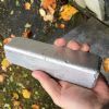
I just bought Beaver VBRP MK2. I am from Czech republic so this milling machine is not usual here. I just found out that gib key is missing. See the pictures please. I assume that I am only one owner this machine in the Czech Republic.
Could you please measure yours and write the dimensions to me? Some basic drawing will be the best. It would be really helpful.
Thank you Kind Regards Martin |
| Mark Rand | 19/06/2018 23:30:07 |
| 1505 forum posts 56 photos | I'm afraid that I cannot help with dimensions for the gib. My machine is a VBRP MK1. All of the drawings I have are for the MK1 as well. Are there any adjusting screws on the left hand side of the saddle? If there are, the gib is parallel and you can measure the dimensions from one end and make a gib that will fit.
If there aren't, then it is a tapered gib and you will need to measure the width of the gap at both ends and make the gib to those dimensions.
If it is a parallel gib, you can make it to nearly the right size and adjust it with the screws. If it is a tapered gib, you really need to make it to the right taper, then scrape it to fit the ways.
If you can, make the gib from cast iron instead of steel. It causes less wear on the other parts of the machine (the original gibs were all cast iron) |
| Martin Zuzák | 20/06/2018 12:18:18 |
| 3 forum posts 6 photos | hank you for your reply.
There are not udjusting screws on the left side of saddle. There are only lock screws. Yes, it is tapered gib. It seems that I will have to measure angle with sinus ruler, but I have to take down the saddle. Cast iron seems the best for it.
Do you know anyone who has drawings for MK2? I have original literature, but there are only basic information how to lubricate and etc… I assume that Beaver factory doesn’t produce milling machine anymore. Right? |
| Peter_H | 20/06/2018 16:32:44 |
| 42 forum posts 20 photos | Beaver/Baldings closed down around about 30 years ago. I am almost certain that I got a pair of spare table gibs when I first had my VBRP Mk2. They are complex double tapered, odd looking things. A thread rod emerges from one end, and this locked with a pair of nuts either side of a fixed part, so they are positively held in both directions after adjustement. I also think they are a right and left handed pair. I could try to take some dimensions from it if you want, and maybe photograph it. Best would be if sommeone could put it on CAD. Later... I have found them, they are a matching pair. Cross section is parallelogram with angles 35/55 degrees. The section is constant height, but tapered width. They are 10 ins long (254mm) At the fat end, the parallellogram is 0.6317 ins (16.045mm) by 0.7351 ins (18.671mm) At the thin end it is 0.4911 ins (12.474mm) by 0.7351 ins (18.671mm) The fat end has a slot 7.4mm wide by 8.81mm deep, 8.34mm from the end. It is the slot that is used to lock the adjustment. The threaded stud I mentioned must be the stationary part. There is a blind hole about 6mm diameter 77.5mm in from the fat end in one face. The part seems to be made of carbon steel and hardened after machining all over. One side looks to be ground then hand scraped flat. There is a witness mark on one face where the table locking screw has pinched on it.
I'll follow up with photographs when I get a chance.
Edited By Peter_H on 20/06/2018 16:34:49 Edited By Peter_H on 20/06/2018 17:13:30 |
| Peter_H | 20/06/2018 17:26:44 |
| 42 forum posts 20 photos | It seems that the two parallel faces, 0.7351 ins apart, sit horizontally in the machine. The scraped face then slopes back from the table and fits under Vee of the table. So moving the gib along the direction of table movement will move the scraped face closer or further from the Vee of the table, thus adjusting clearance. In that attitude, the slot is on the outer end of the gib and cut vertically into the top edge facing the operator. The previously mentioned blind hole and witness mark are in the unscraped sloping face of the gib closest to the operator. This is very difficult to describe in words!.
Hang on... erm, I have described the table gibs. Your picture looks like you are missing a carriage gib. Which is it?
Edited By Peter_H on 20/06/2018 17:31:09 |
| Mark Rand | 20/06/2018 19:17:27 |
| 1505 forum posts 56 photos | The one that Martin is missing is the one between the knee and the saddle. I didn't realize that the table gibs were tapered on the MkII. They certainly made a lot of improvements from the Mk1 ! Edited By Mark Rand on 20/06/2018 19:18:45 |
| Peter_H | 21/06/2018 16:13:56 |
| 42 forum posts 20 photos | I can't remember the details of how that one is fitted, I think it is pushed in as far as necessary against the taper by the screw in Martins photo, and locked by several gib screws on the right of the casting. It is over ten years since I last stripped it though. I do have a spare however, which I just measured. The gib has a single simple taper. It is rectangular with parallel sides 0.745ins (18.923mm) apart. The tapered sides are 0.496ins (12.598mm) at the narrow end and 0.658ins (16.713mm) at the wide end. The two parallel side are machined and the two tapered faces are ground and scraped. Hardened steel again IMO. There is a small groove about 30 thou wide and 30 thou deep across the top parallel face at the wide end, about 0.15ins in from the end. The gib is 241mm long overall. |
| Martin Zuzák | 23/06/2018 09:34:04 |
| 3 forum posts 6 photos | Hello Peter and Mark, Thank you for your help. I really appreciate it. Dimensions what you measured are very similar what I measured. See picture how I measured angle tapered side. I used sinus ruler + (I dont know how to say in English, You will understand from the picture.) The taper is 1 degree. I will make drawing and show to you.
|
| Peter_H | 23/06/2018 11:05:35 |
| 42 forum posts 20 photos | I would call it a Sine Bar. Yes, dimensions sounds very similar. The wear on the part I have would count for some discrepancy. Given that the original part was probably Imperial, and allowing for wear, my guess of original dimensions are : length = 9.5ins = 241.3mm parallel height = 0.75ins = 19.05mm narrow part of taper = 0.5ins = 12.7mm 0.5 + (9.5*sin(1)) = 0.66579ins which is consistent with 1 degree taper |
| john O'Sullivan 4 | 02/10/2020 15:18:22 |
 7 forum posts | Good evening,
have an old beaver mill landed into my garage and hope to get in running over new few months once finish the house build.
My 2 issues are suitable power supply and replace the splined handles what are missing |


![img_0195[1].jpg](/sites/7/images/member_albums/175173/806961.jpg "img_0195[1].jpg")
Please login to post a reply.
Magazine Locator
Want the latest issue of Model Engineer or Model Engineers' Workshop? Use our magazine locator links to find your nearest stockist!
Sign up to our Newsletter
Sign up to our newsletter and get a free digital issue.
You can unsubscribe at anytime. View our privacy policy at www.mortons.co.uk/privacy
Latest Forum Posts
- hemingway ball turner
04/07/2025 14:40:26 - *Oct 2023: FORUM MIGRATION TIMELINE*
05/10/2023 07:57:11 - Making ER11 collet chuck
05/10/2023 07:56:24 - What did you do today? 2023
05/10/2023 07:25:01 - Orrery
05/10/2023 06:00:41 - Wera hand-tools
05/10/2023 05:47:07 - New member
05/10/2023 04:40:11 - Problems with external pot on at1 vfd
05/10/2023 00:06:32 - Drain plug
04/10/2023 23:36:17 - digi phase converter for 10 machines.....
04/10/2023 23:13:48 - More Latest Posts...
- View All Topics
Support Our Partners


Shopping Partners
Subscription Offer

Latest "For Sale" Ads
- Reeves** - Rebuilt Royal Scot by Martin Evans
by John Broughton
£300.00 - BRITANNIA 5" GAUGE James Perrier
by Jon Seabright 1
£2,500.00 - Drill Grinder - for restoration
by Nigel Graham 2
£0.00 - WARCO WM18 MILLING MACHINE
by Alex Chudley
£1,200.00 - MYFORD SUPER 7 LATHE
by Alex Chudley
£2,000.00 - More "For Sale" Ads...
Latest "Wanted" Ads
- D1-3 backplate
by Michael Horley
Price Not Specified - fixed steady for a Colchester bantam mark1 800
by George Jervis
Price Not Specified - lbsc pansy
by JACK SIDEBOTHAM
Price Not Specified - Pratt Burnerd multifit chuck key.
by Tim Riome
Price Not Specified - BANDSAW BLADE WELDER
by HUGH
Price Not Specified - More "Wanted" Ads...
Get In Touch!
Do you want to contact the Model Engineer and Model Engineers' Workshop team?
You can contact us by phone, mail or email about the magazines including becoming a contributor, submitting reader's letters or making queries about articles. You can also get in touch about this website, advertising or other general issues.
Click THIS LINK for full contact details.
For subscription issues please see THIS LINK.
Digital Back Issues


Donate

 Register
 Log-in
Model Engineer Magazine
- Percival Marshall
- M.E. History
- LittleLEC
- M.E. Clock

ME Workshop
- An Adcock
- & Shipley
- Horizontal
- Mill

Subscribe Now
- Great savings
- Delivered to your door

Pre-order your copy!
- Delivered to your doorstep!
- Free UK delivery!
All Forum Topics > Manual machine tools > Restoring Beaver VBRP Mill