Forum sponsored by:

Home Made Rear Toolpost Issue
| not done it yet | 05/04/2021 20:48:21 |
| 7517 forum posts 20 photos | As demonstrated in that video on Martin’s post, you can measure to the ‘n’ th degree but if there is any deflection, while under load, it will count for nothing. Altering the cutter overhang, for parting different diameter stock, will make a difference. There will be some deflection - make no doubt about that - on a worn hobby lathe. Practicality will trump theory for most of us. |
| Dr_GMJN | 05/04/2021 22:13:43 |
 1602 forum posts | Posted by Howard Lewis on 05/04/2021 18:51:29:
Slips are accurate to millionths of an inch, so no need to risk damage by not using the protectives. If scratched, or worn, they will no longer wring together, and then be difficult to stack for other dimensional checks. Not sure that using for direct measurement on a machine is really a proper use for them. Howard Thanks Howard, I’d have to get rid of the PVA glue off them first - I find a Brillo pad is quite effective for this. |
| Grindstone Cowboy | 05/04/2021 22:20:00 |
| 1160 forum posts 73 photos |
|
| Dr_GMJN | 05/04/2021 22:27:48 |
1602 forum posts | Posted by Grindstone Cowboy on 05/04/2021 22:20:00:
Nope. I bought them solely for the purpose of weighting down decks and other parts of card ships while the PVA sets. The different sizes are handy to fit between various stiffeners and bulkheads. I bought them a few years ago off Ebay for £30. Incomplete set, and I have no idea of their accuracy, so wouldn’t trust them to be used as intended anyway. Some wring together, some don’t. They do come in handy for general use as parallels/packers though - accurate enough for the things I’m doing. OK the Brillo pad was a joke - I use water soluble PVA so just dunk them in hot water ha ha. |
| Dr_GMJN | 05/04/2021 22:41:57 |
1602 forum posts | So the largest diameter I can envisage parting in the near future is c.42mm cast iron, for steam engine cylinder caps. By pure dumb luck, the projection of the blade is just enough, plus a bit, for that. So once set by trial and error, that will be it for the rear post. For turning tools, I can imagine spending hours making a setting gauge, then ending up re-setting by trial and error anyway, depending on tool projection, workpiece overhang and material type. Maybe I’m being defeatist, but most fettling I do on the lathe (eg tailstock alignment) seems to end up in a compromise due to inherent wear. I can’t see tool height being any different. |
| Dr_GMJN | 05/04/2021 23:32:05 |
1602 forum posts | Re. the toolpost being left in-situ, and the front clamp causing an obstruction: This is a top view of the lathe showing the front toolpost, and rear post turned 90 degrees. The front post is usually angled a bit, and the tool not extended as much, which makes the relative clearances shown fairly representative. You can see that there is not much room with the rear post in place, and it’s far less risky and stressful to simply remove it: |
| Howard Lewis | 06/04/2021 07:20:18 |
| 7227 forum posts 21 photos | Yes, see what you mean. The Cross Slide is a bit short to carry both posts when machining large diameter stuff. I fitted my ML7 with the long Cross Slide, so did not have that problem. And the one on the present lathe is long enough to carry both. The problem here is that the rear post fouls the Chuck guard when using a collet chuck, and has to be removed to work close up to the Headstock. Horrified at thought of PVA on slips! NO Brillo pad. NO olistone / diamond lap. PVA is water soluble, so soak it off. If the slips won't wring together, it is too late. But they should still be the most accurate piece of equipment for measuring that you have, so take care of them.. At least you are now set to have fewer, if any, parting problems. Howard |
| JasonB | 06/04/2021 07:31:19 |
 25215 forum posts 3105 photos 1 articles | You have got a lot too much of that turning tool projecting out of the front toolpost, move it back into the holder say 20-25mm by the looks of things and then you will have more clearance behind. |
| not done it yet | 06/04/2021 08:44:30 |
| 7517 forum posts 20 photos | Posted by JasonB on 06/04/2021 07:31:19:
You have got a lot too much of that turning tool projecting out of the front toolpost, move it back into the holder say 20-25mm by the looks of things and then you will have more clearance behind. Dead right! It looks like it only needs ~6mm to clear the work, so a workpiece of 80mm diameter should be easily possible. |
| John Baron | 06/04/2021 09:01:04 |
 520 forum posts 194 photos | Posted by Dr_GMJN on 05/04/2021 23:32:05:
This is a top view of the lathe showing the front toolpost, and rear post. The front post is usually angled a bit, and the tool not extended as much, which makes the relative clearances shown fairly representative. You can see that there is not much room with the rear post in place, and it’s far less risky and stressful to simply remove it: Hi Dr GMJN, I agree with your comment about completely removing the rear TP when not needed. I don't remove mine, but then I have the extended cross slide. However looking at your second picture and putting a rule across between the two tools, there is a definite height difference between them ! I assume that you are going to make a tool height setting gauge. If so you will be able to instantly see which is right. While I think about it, the height given it the drawing that I posted needs to be adjusted to suit your centre height. I did mention how I did it on mine. I really don't understand why it should be so difficult to get and set the tool height. I made and use the "Norman Patent" tool posts on both front and back of my cross slide ! No shims needed and always dead on height. Actually I think that making one is a very good turning and boring exercise.
|
| SillyOldDuffer | 06/04/2021 10:42:24 |
| 10668 forum posts 2415 photos | Posted by Howard Lewis on 06/04/2021 07:20:18: ... Horrified at thought of PVA on slips! NO Brillo pad. NO olistone / diamond lap. PVA is water soluble, so soak it off. If the slips won't wring together, it is too late. But they should still be the most accurate piece of equipment for measuring that you have, so take care of them... I'm with Dr_GMJN on this one! Gauge blocks exist to produce precision measurements by stacking, and an un-calibrated second-hand set fails at the first hurdle because used blocks cannot be trusted. They might as well be used as weights and shims. What exactly are Gauge Blocks for in a home workshop? Bought for their feel-good factor rather than practical use maybe? (If so, I've no objection to pride of ownership, but it's not engineering!) Model Engineering and most repair work is done using fit by comparison techniques rather than being made within carefully measured tolerances as part of an industrial process set up specifically to make interchangeable parts. Not many model-engineers justify their Gauge Block purchases by making precision jigs, fixtures and Go - NoGo gauges! More common to hear of Gauge Blocks being used to validate digital calipers and micrometers, the idea being that even in poor condition, slips should be more accurate than the tool being tested. Well, maybe, but does the absolute accuracy of a micrometer matter much either when the owner is a fitter? My cynical streak suspect these things are all toys for boys. Just for fun I experimented with the sort of turning methods used before Micrometers and other precision workshop metrology was generally available. Ordinary spring calipers work remarkably well, the main problem being the need to develop a 'feel', and the extra time it takes. Have a go and see what you think. Put it this way, if all Gauge Blocks were confiscated by Duffer's ultra-radical enforcers, what exactly would model engineers be unable to make in their workshops? Be honest!
Dave
Edited By SillyOldDuffer on 06/04/2021 10:45:04 |
| not done it yet | 06/04/2021 11:00:57 |
| 7517 forum posts 20 photos | I’m with you there, Dave! (The boxes are heavy to lift as well 🙂 ) I have a set and have used them occasionally - but they are better than my machining capability in general. I need to be using the surface grinder to justify using them in routine machining. |
| Circlip | 06/04/2021 11:08:59 |
| 1723 forum posts | Heresy, Slips are a must have, just as a Mifford is the only ME tool to have. Used a slip gauge set many years ago when I was a prentice toolmaker, a micro screw jack and mics substitute for the "Adjustable packings" housed in either a wooden or plastic case. Regards Ian. |
| Michael Gilligan | 06/04/2021 11:20:26 |
 23121 forum posts 1360 photos | Posted by SillyOldDuffer on 06/04/2021 10:42:24: […] I'm with Dr_GMJN on this one! Gauge blocks exist to produce precision measurements by stacking, and an un-calibrated second-hand set fails at the first hurdle because used blocks cannot be trusted. They might as well be used as weights and shims. […]
‘Down-cycling’ is a worthy tradition : **LINK** https://www.hemmings.com/stories/2013/03/06/theres-a-coupe-joke-in-this-im-sure MichaelG. |
| Hopper | 06/04/2021 12:23:29 |
 7881 forum posts 397 photos | Posted by Dr_GMJN on 03/04/2021 16:58:27:
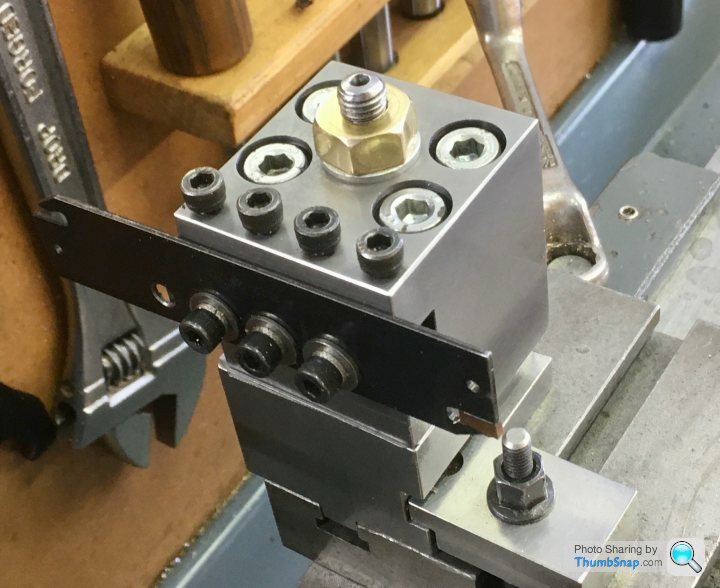
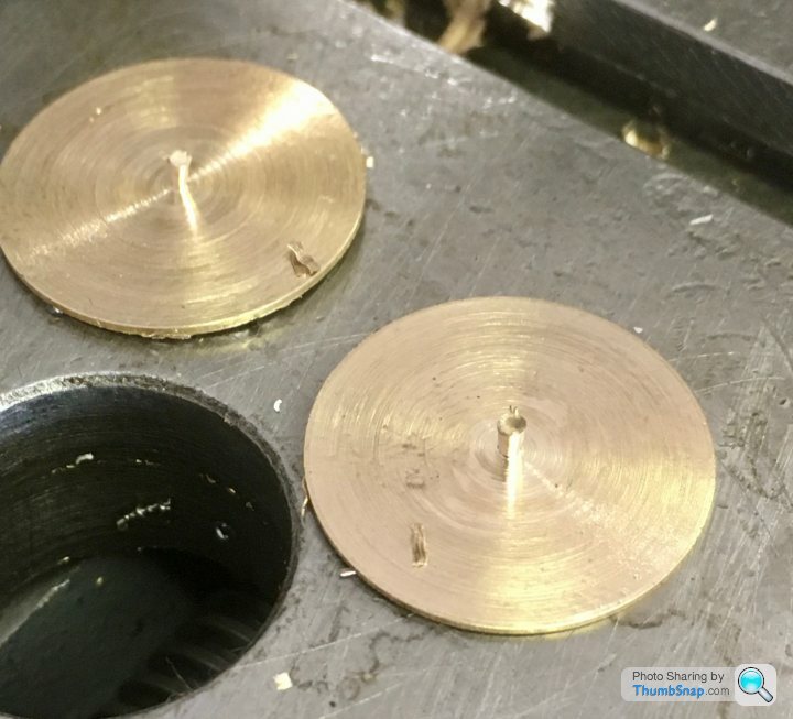
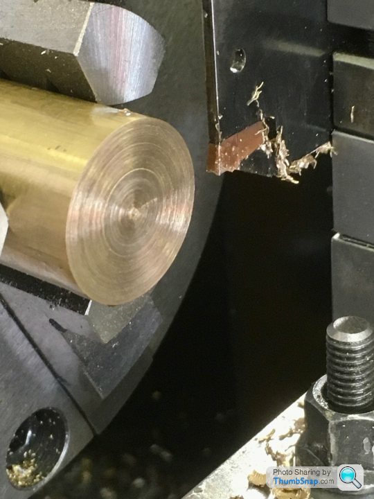
So I've repaired the rear toolpost as suggested with some S275 steel, and M8 capheads: To be fair, a bit of brass bar is hardly any kind of test for parting off. The stuff machines so easily regardless of tool attitude or just about anything else. Try a comparison front/rear test on a piece of 1" STEEL bar and then a piece of 1.5" steel bar. You'll get a lot more swarf jamming and micro-welding and dig ins and other unpleasantness with steel, which the upside down tool may help to alleviate. Another thing is that when GH Thomas, Sparey, Duplex and co were extolling the virtues of rear toolposts, they had no choice but the old tapered profile HSS blades, which were prone to jamming on the sides of the groove with swarf. Your carbide insert is wider than the shank that holds it, providing that much needed clearance for swarf particles to pass through relatively unmolested. Also, it looks like it has a divot in the top cutting surface so curls the chip up narrower than the slot it cuts, thus avoiding more swarf jams. Like the Eccentric Engineering T section HSS blade I posted a thread about recently, your insert tooling will work much better right way up than the old tapered blades. One thing GHT and Co. got right was making their toolposts a heavy L section with two bolts through the foot of the L so the vertical body stuck out behind the cross slide, giving you an extra 1.5 inches of room there behind the job when not in use. You could use yours as a quick removeable single bolt rear toolpost and just whip it on and off as needed. That's what I do on the old Drummond. Has been working that way since World War 2 or a bit earlier as far as I know.
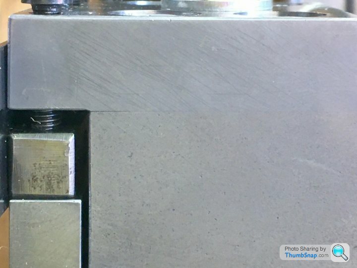
PS Seems odd that you have that gap opening up when you clamp the tool on your modified post. Unless you are putting massive torque on those clamping screws that should not be happening. I'd check that the silver allen screws are not bottoming on their threads prematurely. Also make sure the bottoms of the countersunk holes they sit in are properly square shouldered, not drilled at an angle with standard pointed drill bit. And then torque those silver screws up with a 12" piece of pipe over the allen key. Dont strip them, but make them damn tight. (As they say in Harley Davidson circles, do 'em up til they strip, then back 'em off quarter of a turn. ) |
| Zan | 06/04/2021 13:04:54 |
| 356 forum posts 25 photos | Slips are extremely useful and mine see a lot of use. Yesterday I was making a yoke for crankshaft to work in. The slips made it very very easy to get file the gauge plate material easily to a very smooth and polished finish. Yes the slot ended up 4 thou too small but I’ll make the split bearing to fit mine are second hand, from two sets at a total cost of £35.. I can’t work to the limits which a new on spec set would “ measure” to. They just about stack, but I’m very pleased with the number of times I use them heres the yoke clamped to align the cylinder bridge on the pump, but before finishing the 0.309” yoke sorry it’s upside dow, I switched it over before uploading, but still wrong! Edited By Zan on 06/04/2021 13:23:00 |
| Dr_GMJN | 06/04/2021 13:29:21 |
1602 forum posts | Thanks guys - a few points, which to be fair I did mention in various posts: As I said, some types of PVA are water soluble, and again, I said I removed it from the slip gauges by soaking in warm water. I did mention that the tool projection was excessive in the picture (can't remember why, but that's how I'd left it), but the tool post is often turned at an angle, so even with reduced overhang, the gap is representative - and it's not nice to be constrained between two immovable objects while machining. I also mentioned that I'd used a socket wrench to re-tighten the M8 capheads, and that opening up isn't an issue now. Regarding parting off on brass - I figured that if it wasn't working properly on brass, it sure wouldn't on steel. I'd rather do the setting on easier to machine materials. I'm waiting for some longer M5 clamp bolts to arrive, on which I'll remove the end threads and face the ends. And yes, the insert is profiled to curl the swarf with a central bulge - they work well, but because they are asymmetric, it's making height setting a bit more difficult. The blade holder also tends to spring away from the workpiece at the final bit of the cut, which itself leaves a pip. I'll sort it eventually. Cheers. |
| Howard Lewis | 06/04/2021 21:34:24 |
| 7227 forum posts 21 photos | Use of slips depends on your background, and the standards you set, (Even, if my case there is great difficulty in working to them ). Having spent the major part of my working life in Quality and therefor spending a lot of time with Inspection, Standards Room and Calibration Room, I am obviously biased. Can anyone say why, if they are so useless, Industry uses slips? If they wring together the condition is good enough to say that they are accurate. Even if they don't, but have no obvious damage, they can be used as standards which are far more accurate than anything else in the usual hobby workshop. I last used mine (Which are old and some do not wring together ) to measure a lipseal OD and the bore for it, so that the right interference could be accurately achieved. Before that, to ensure that a there would be the required interference on a "Heat and Freeze" assembly, when cold.. Each to his own. Howard |
| not done it yet | 06/04/2021 22:17:44 |
| 7517 forum posts 20 photos | I would guess that one of the most common practical uses in the workshop is to accurately gauge the width of a slot, to be able to finish it exactly on size - so that a standard key will fit tightly without clearance? Sine blocks and angles is another, I suppose? I’ve several repairs to make where shrink fitting a piece of metal into a slot is required. I would make tight fitting ‘go’ plug on one edge of a strip and then use a piece machined just slightly bigger for the shrink fit. My slip gauges will most certainly hasten that job. These slots are only a very few mm wide in thinnish cast iron and really need to be invisible after repair. What other regular uses do people use them for? Marking out?...? ...? |
| Dr_GMJN | 06/04/2021 22:53:43 |
1602 forum posts | Posted by Howard Lewis on 06/04/2021 21:34:24:
Use of slips depends on your background, and the standards you set, (Even, if my case there is great difficulty in working to them ). Having spent the major part of my working life in Quality and therefor spending a lot of time with Inspection, Standards Room and Calibration Room, I am obviously biased. Can anyone say why, if they are so useless, Industry uses slips? If they wring together the condition is good enough to say that they are accurate. Even if they don't, but have no obvious damage, they can be used as standards which are far more accurate than anything else in the usual hobby workshop. I last used mine (Which are old and some do not wring together ) to measure a lipseal OD and the bore for it, so that the right interference could be accurately achieved. Before that, to ensure that a there would be the required interference on a "Heat and Freeze" assembly, when cold.. Each to his own. Howard Not sure anyone said they were useless. It's just that - for me - a second hand set of slip gauges bought off EBay is far more use for different sized, flat weights for model building, or packing pieces for setting up work, than for the high-accuracy metrology work they were intended for in industry. It's nothing to do with the standards I set for myself, just that its not worth the bother of using them with the care they demand, in my workshop/garage. For example - is your workshop temperature controlled to 20 degrees C +/- 0.1 degree? Do you use chamois gloves to handle them? It's not like I deliberately throw then on the floor or dip them in salt water, and I'm happy to use some odd ones to check that a micrometer or vernier is about right, but that's as far as it goes. The stuff I'm doing doesn't seem to require absolute precision, so long as things fit together nicely and don't rattle, I'm fairly happy. Don't get me wrong - I'm not some caveman, and I do look after my tools as best I can, but when equipment starts to take more effort to use correctly in a home workshop than the results justify, frankly, what's the point? |


Please login to post a reply.
Magazine Locator
Want the latest issue of Model Engineer or Model Engineers' Workshop? Use our magazine locator links to find your nearest stockist!
Sign up to our Newsletter
Sign up to our newsletter and get a free digital issue.
You can unsubscribe at anytime. View our privacy policy at www.mortons.co.uk/privacy
Latest Forum Posts
- hemingway ball turner
04/07/2025 14:40:26 - *Oct 2023: FORUM MIGRATION TIMELINE*
05/10/2023 07:57:11 - Making ER11 collet chuck
05/10/2023 07:56:24 - What did you do today? 2023
05/10/2023 07:25:01 - Orrery
05/10/2023 06:00:41 - Wera hand-tools
05/10/2023 05:47:07 - New member
05/10/2023 04:40:11 - Problems with external pot on at1 vfd
05/10/2023 00:06:32 - Drain plug
04/10/2023 23:36:17 - digi phase converter for 10 machines.....
04/10/2023 23:13:48 - More Latest Posts...
- View All Topics
Support Our Partners


Shopping Partners
Subscription Offer

Latest "For Sale" Ads
- Reeves** - Rebuilt Royal Scot by Martin Evans
by John Broughton
£300.00 - BRITANNIA 5" GAUGE James Perrier
by Jon Seabright 1
£2,500.00 - Drill Grinder - for restoration
by Nigel Graham 2
£0.00 - WARCO WM18 MILLING MACHINE
by Alex Chudley
£1,200.00 - MYFORD SUPER 7 LATHE
by Alex Chudley
£2,000.00 - More "For Sale" Ads...
Latest "Wanted" Ads
- D1-3 backplate
by Michael Horley
Price Not Specified - fixed steady for a Colchester bantam mark1 800
by George Jervis
Price Not Specified - lbsc pansy
by JACK SIDEBOTHAM
Price Not Specified - Pratt Burnerd multifit chuck key.
by Tim Riome
Price Not Specified - BANDSAW BLADE WELDER
by HUGH
Price Not Specified - More "Wanted" Ads...
Get In Touch!
Do you want to contact the Model Engineer and Model Engineers' Workshop team?
You can contact us by phone, mail or email about the magazines including becoming a contributor, submitting reader's letters or making queries about articles. You can also get in touch about this website, advertising or other general issues.
Click THIS LINK for full contact details.
For subscription issues please see THIS LINK.
Digital Back Issues


Donate

 Register
 Log-in
Model Engineer Magazine
- Percival Marshall
- M.E. History
- LittleLEC
- M.E. Clock

ME Workshop
- An Adcock
- & Shipley
- Horizontal
- Mill

Subscribe Now
- Great savings
- Delivered to your door

Pre-order your copy!
- Delivered to your doorstep!
- Free UK delivery!
All Forum Topics > Workshop Tools and Tooling > Home Made Rear Toolpost Issue